- Electric and Telecom Plans Free
- Fire and Emergency Plans Free
- Floor Plans Free
- Plant Layout Plans Free
- School and Training Plans Free
- Seating Plans Free
- Security and Access Plans Free
- Site Plans Free
- Sport Field Plans Free
- Business Process Diagrams Free
- Business Process Mapping Free
- Classic Business Process Modeling Free
- Cross-Functional Flowcharts Free
- Event-driven Process Chain Diagrams Free
- IDEF Business Process Diagrams Free
- Logistics Flow Charts Free
- Workflow Diagrams Free
- ConceptDraw Dashboard for Facebook Free
- Mind Map Exchange Free
- MindTweet Free
- Note Exchange Free
- Project Exchange Free
- Social Media Response Free
- Active Directory Diagrams Free
- AWS Architecture Diagrams Free
- Azure Architecture Free
- Cisco Network Diagrams Free
- Cisco Networking Free
- Cloud Computing Diagrams Free
- Computer Network Diagrams Free
- Google Cloud Platform Free
- Interactive Voice Response Diagrams Free
- Network Layout Floor Plans Free
- Network Security Diagrams Free
- Rack Diagrams Free
- Telecommunication Network Diagrams Free
- Vehicular Networking Free
- Wireless Networks Free
- Comparison Dashboard Free
- Composition Dashboard Free
- Correlation Dashboard Free
- Frequency Distribution Dashboard Free
- Meter Dashboard Free
- Spatial Dashboard Free
- Status Dashboard Free
- Time Series Dashboard Free
- Basic Circle-Spoke Diagrams Free
- Basic Circular Arrows Diagrams Free
- Basic Venn Diagrams Free
- Block Diagrams Free
- Concept Maps Free
- Family Tree Free
- Flowcharts Free
- Basic Area Charts Free
- Basic Bar Graphs Free
- Basic Divided Bar Diagrams Free
- Basic Histograms Free
- Basic Line Graphs Free
- Basic Picture Graphs Free
- Basic Pie Charts Free
- Basic Scatter Diagrams Free
- Aerospace and Transport Free
- Artwork Free
- Audio, Video, Media Free
- Business and Finance Free
- Computers and Communications Free
- Holiday Free
- Manufacturing and Maintenance Free
- Nature Free
- People Free
- Presentation Clipart Free
- Safety and Security Free
- Analog Electronics Free
- Audio and Video Connectors Free
- Basic Circuit Diagrams Free
- Chemical and Process Engineering Free
- Digital Electronics Free
- Electrical Engineering Free
- Electron Tube Circuits Free
- Electronic Block Diagrams Free
- Fault Tree Analysis Diagrams Free
- GHS Hazard Pictograms Free
- Home Automation and Wiring Free
- Mechanical Engineering Free
- One-line Diagrams Free
- Power Сircuits Free
- Specification and Description Language (SDL) Free
- Telecom and AV Circuits Free
- Transport Hazard Pictograms Free
- Data-driven Infographics Free
- Pictorial Infographics Free
- Spatial Infographics Free
- Typography Infographics Free
- Calendars Free
- Decision Making Free
- Enterprise Architecture Diagrams Free
- Fishbone Diagrams Free
- Organizational Charts Free
- Plan-Do-Check-Act (PDCA) Free
- Seven Management and Planning Tools Free
- SWOT and TOWS Matrix Diagrams Free
- Timeline Diagrams Free
- Australia Map Free
- Continent Maps Free
- Directional Maps Free
- Germany Map Free
- Metro Map Free
- UK Map Free
- USA Maps Free
- Customer Journey Mapping Free
- Marketing Diagrams Free
- Matrices Free
- Pyramid Diagrams Free
- Sales Dashboard Free
- Sales Flowcharts Free
- Target and Circular Diagrams Free
- Cash Flow Reports Free
- Current Activities Reports Free
- Custom Excel Report Free
- Knowledge Reports Free
- MINDMAP Reports Free
- Overview Reports Free
- PM Agile Free
- PM Dashboards Free
- PM Docs Free
- PM Easy Free
- PM Meetings Free
- PM Planning Free
- PM Presentations Free
- PM Response Free
- Resource Usage Reports Free
- Visual Reports Free
- House of Quality Free
- Quality Mind Map Free
- Total Quality Management TQM Diagrams Free
- Value Stream Mapping Free
- Astronomy Free
- Biology Free
- Chemistry Free
- Language Learning Free
- Mathematics Free
- Physics Free
- Piano Sheet Music Free
- Android User Interface Free
- Class Hierarchy Tree Free
- Data Flow Diagrams (DFD) Free
- DOM Tree Free
- Entity-Relationship Diagram (ERD) Free
- EXPRESS-G data Modeling Diagram Free
- IDEF0 Diagrams Free
- iPhone User Interface Free
- Jackson Structured Programming (JSP) Diagrams Free
- macOS User Interface Free
- Object-Role Modeling (ORM) Diagrams Free
- Rapid UML Free
- SYSML Free
- Website Wireframe Free
- Windows 10 User Interface Free
SYSML
SysML is known to be an abbreviation for the Systems Modeling Language. It is a general-purpose modeling language that is widely used for many systems engineering applications which supports the analysis, design, specification, validation, and verification of a broad range of systems-of-systems as well as systems.
SysML is also known for including an open source license for both use and distribution being defined as an extension of the Unified Modeling Language subset using the so-called “UML's profile mechanism”. Language extensions were originally designed to support many systems engineering activities.
Offering systems engineers a few noteworthy improvements over UML, the improvements of the SysML include its semantics being more expressive and flexible. In addition, it reduces many of the UML's software-centric restrictions, adding two new diagram types: parametric and requirement diagrams.
SysML can model many different systems, which may include software, information, hardware, processes, facilities, and personnel which make it very popular, nevertheless, it is a comparatively little language, but it is known to be easier to both apply and learn. SysML can furnish those flexible allocation tables that support functional, structural and requirements allocations which facilitate the validation, the so-called “gap” analysis and the automated verification.
In order to make a SysML-related drawing, the ConceptDraw DIAGRAM charting and drawing software can be used. Also, the SysML solution can be found as an extension to the ConceptDraw DIAGRAM application, enabling all those with systems engineering background to use the offered tools for creating the needed systems process models in order to use in the professional documentation for either distribution or analysis.
Offering the vector stencil libraries full of the icons that may relate to each of the 9 official diagrams used in SysML (e.g., activity, block definition style, requirements diagrams, etc.), the SysML solution can be useful for many system engineers who are interested in creating efficient, highly detailed diagrams that are easy to create because they can be based on previously made professional-looking examples.
-
Install this solution Free -
What I need to get started -
Solution Requirements - This solution requires the following products to be installed:
ConceptDraw DIAGRAM v18 - This solution requires the following products to be installed:
-
Compatibility - Sonoma (14), Sonoma (15)
MS Windows 10, 11 - Sonoma (14), Sonoma (15)
-
Support for this Solution -
Helpdesk
There are 13 stencil libraries containing 284 vector objects in the SysML (Systems Modeling Language) solution.
Design Elements — SysML Activity Diagram

Design Elements — SysML Allocations

Design Elements — SysML Block Definition Diagram

Design Elements — SysML Internal Block Diagram

Design Elements — SysML Package Diagram

Design Elements — SysML Parametric Diagram

Design Elements — SysML Ports and Flows

Design Elements — SysML Profiles and Model

Design Elements — SysML Requirement Diagram

Design Elements — SysML Sequence Diagram

Design Elements — SysML State Machine Diagram

Design Elements — SysML Diagrams

Design Elements — SysML Use Case Diagram

Related News:
Examples
There are a few samples that you see on this page which were created in the ConceptDraw DIAGRAM application by using the SYSML solution. Some of the solution's capabilities as well as the professional results which you can achieve are all shown here on this page.
All source documents are vector graphic documents which are always available for modifying, reviewing and/or converting to many different formats, such as MS PowerPoint, PDF file, MS Visio, and many other graphic ones from the ConceptDraw Solution Park or ConceptDraw STORE. The SYSML solution is available to all ConceptDraw DIAGRAM users to get installed and used while working in the ConceptDraw DIAGRAM charting and drawing software.
Example 1: SysML Diagram — Builder Design Pattern Sequence
This diagram was created in ConceptDraw DIAGRAM using the Block Definition Diagram library from the SysML solution. An experienced user spent 20 minutes creating this sample.
This SysML Sequence diagram sample is based on the “Builder design pattern sequence1.png” file from the Wikimedia Commons and illustrates a Builder design pattern, which is one of the 'Gang of Four' design patterns. The Builder pattern is used to create complex objects with constituent parts that must be built in a specific order, provides flexible ways for solving recurring design problems and object creation problems in object-oriented programming. It allows separating the complex object construction from its representation and ensures creation of different representations of a complex object. Besides, the Builder pattern lets you vary a product’s internal representation, ensures the control over all steps of the construction process, and allows encapsulating the code for construction and representation. The same model can be used in many different products. This SysML Sequence diagram shows the run-time interactions between aClient, aDirector, and aConcrete Builder objects, which sequentially call the corresponding functions.

Example 2: SysML Diagram — Identity Requirements Diagram
This diagram was created in ConceptDraw DIAGRAM using the Block Definition Diagram and Allocations libraries from the SysML solution. An experienced user spent 25 minutes creating this sample.
This SysML example was created based on the SysML identity requirements diagram from the FreeIPA website. Requirements diagrams exist in their own diagram subcategory — they use both structural and behavioral elements to describe which objects require what actions to develop the process. This diagram describes the requirements for upstream identity providers and identities processing at the moment when they enter the local domain. You can find a prototype implementation of a "merged domain" in a collaboration context. The identity merging service contains the information necessary to bind against upstream identity sources. Local groups can contain users from local and upstream identifiers, the same username is used for all hosts and services in the domain, attribute values must be locally unique, clients in the local domain do not require credentials in the upstream domain. The following are implemented: local control over user attributes, local management of conflicts between them and centralized management of all identities to which local machines and services have access.

Example 3: SysML Activity Diagram
This diagram was created in ConceptDraw DIAGRAM using the Activity Diagram library from the SysML solution. An experienced user spent 10 minutes creating this sample.
This SysML Activity diagram example was designed based on the chart from the "SysML Modelling Language explained" document published on the Official OMG SysML site. SysML Activity diagram is one of the most common ways in systems engineering used to break down a process into all possible steps. It clearly presents the process steps and displays input and output pins. The SysML extends the opportunities of a popular UML language, in particular the management capabilities to support disabling of actions that are performed, the definition of continuous or discrete flow rate, as well as the rate and probability on the control or object flows. The SysML diagrams of different types created using ConceptDraw DIAGRAM SysML and UML tools make a process easily understandable and visually engaging. Besides, their construction with ConceptDraw's SysML solution drawing tools is fast and easier than ever, simply take ready-made objects from the vector stencils libraries and arrange them in a clear diagram.

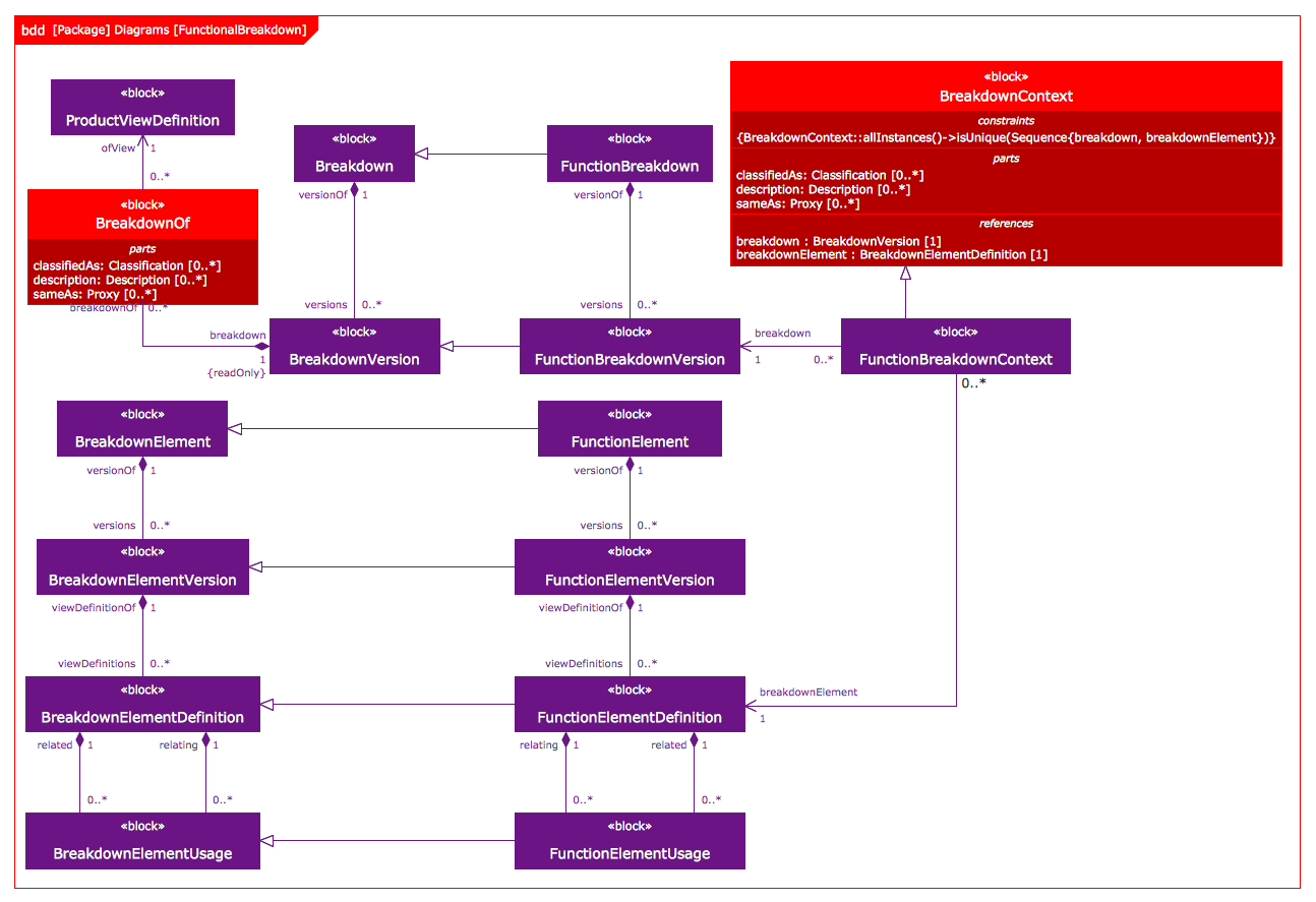
Example 4: SysML Block Definition Diagram
This diagram was created in ConceptDraw DIAGRAM using the Block Definition Diagram library from the SysML solution. An experienced user spent 20 minutes creating this sample.
This SysML Block definition diagram example was designed based on the illustration from the "Template: OASIS: FunctionalBreakdownStructure" webpage published on the OASIS website. The Block definition diagram is based on the UML Class diagram, with special restrictions and extensions predefined by the SysML specification. It lets describe your system structure and model the system hierarchy, present the blocks, their properties and features, as well as outline the structural relationships and dependencies between these blocks. This sample presents a Function breakdown model and visualizes how a functional breakdown is represented in the PLCS PSM (PLCS Platform Specific Model). The PLCS PSM objects are required to represent the template FunctionalBreakdownStructure. Using SysML ensures that your diagrams will be universally understood by other system engineers and all stakeholders. The ConceptDraw DIAGRAM and SysML solutions fully support the SysML notation and provide the professional tools to simplify the systems engineering process and create professional-looking documents using a standardized notation.

Example 5: Use Case Restaurant Model
This diagram was created in ConceptDraw DIAGRAM using the Internal Block Diagram and Activity Diagram libraries from the SysML solution. An experienced user spent 15 minutes creating this sample.
The best system models allow clearly offering the information according to the system, with structure and workflow easily inferred from concise and coherent graphic elements. The SysML solution makes ConceptDraw DIAGRAM the most effective and powerful design choice for system engineers. This sample depicts a model of a restaurant business in a form of Use Case diagram and was designed based on the Wikimedia Commons file "Use case restaurant model.svg". The interactions between a restaurant business system and its primary stakeholders — business actors and business workers are illustrated. Four actors (Client, Chef, Waiter, and Cashier) are involved in a process and depicted in this diagram with men pictograms. At this, the Waiter, Chef, and Cashier are considered as a part of the restaurant system and are the business workers, while the business actor Client is outside a considered system and directly interacts with it. All possible use cases, the usage of a system by actors and interactions between them to achieve the main goal are presented.

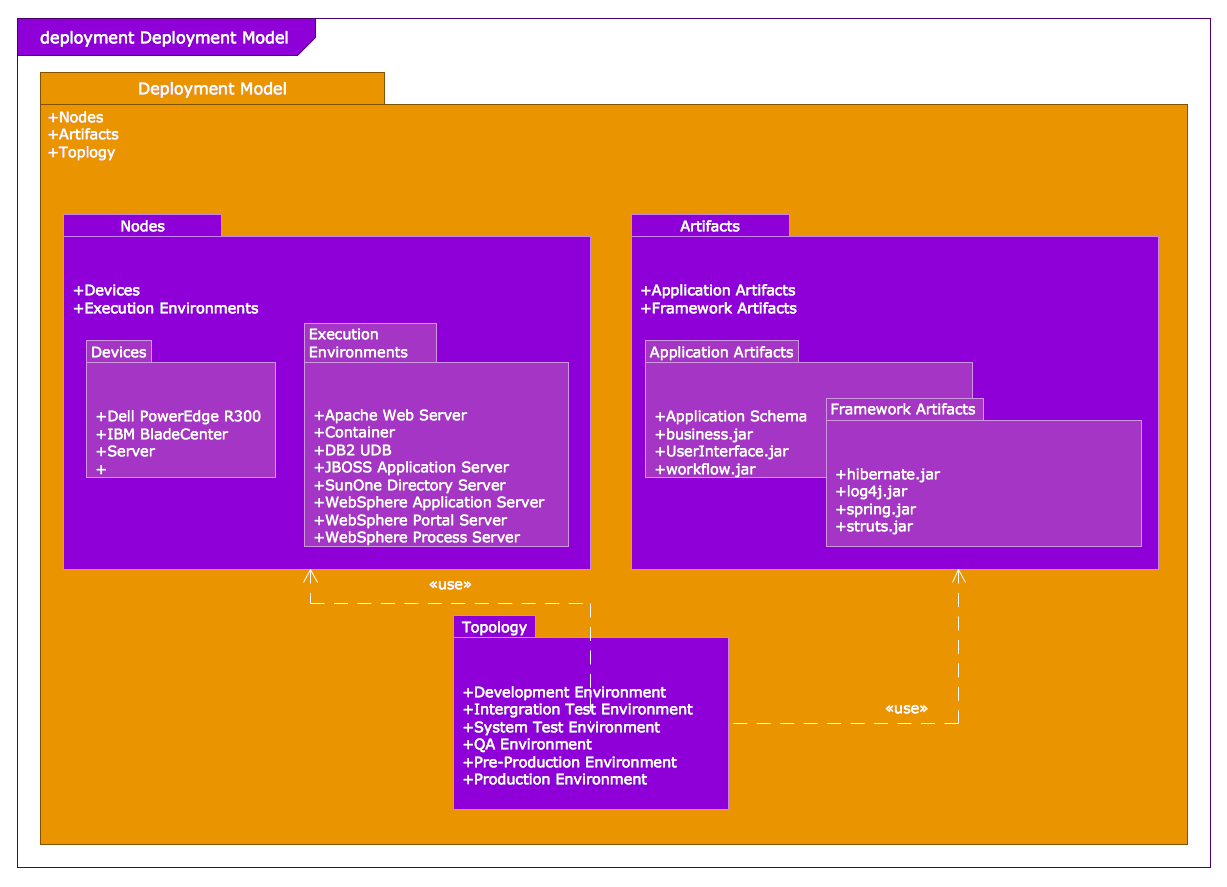
Example 6: Package Diagram – Deployment Model Structure
This diagram was created in ConceptDraw DIAGRAM using the Internal Block Diagram and Activity Diagram libraries from the SysML solution. An experienced user spent 15 minutes creating this sample.
This SysML Package diagram example illustrates a Deployment model structure and was designed based on the Wikimedia Commons file “Deployment Model Structure.PNG”. The SysML Package diagrams are the ideal type of diagrams to be used to visually depict the functionality of a software system and all dependencies between the packages that make up a model. As general, the packages are a universal mechanism for organizing the model elements and diagrams into groups, to group semantically related elements. They are used to depict the different layers of a software system, so to visualize the layered architecture, and may include the use cases. The communication mechanisms can differ from the layer to layer, the labels on the dependencies help to clarify and indicate the used ones. One can benefit from the use of Package diagrams as a way to depict the dependencies between the elements for the systems of any size and complexity, especially they are useful for large scale systems. Due to ConceptDraw’s SysML solution the model based systems engineering is now easier than ever.

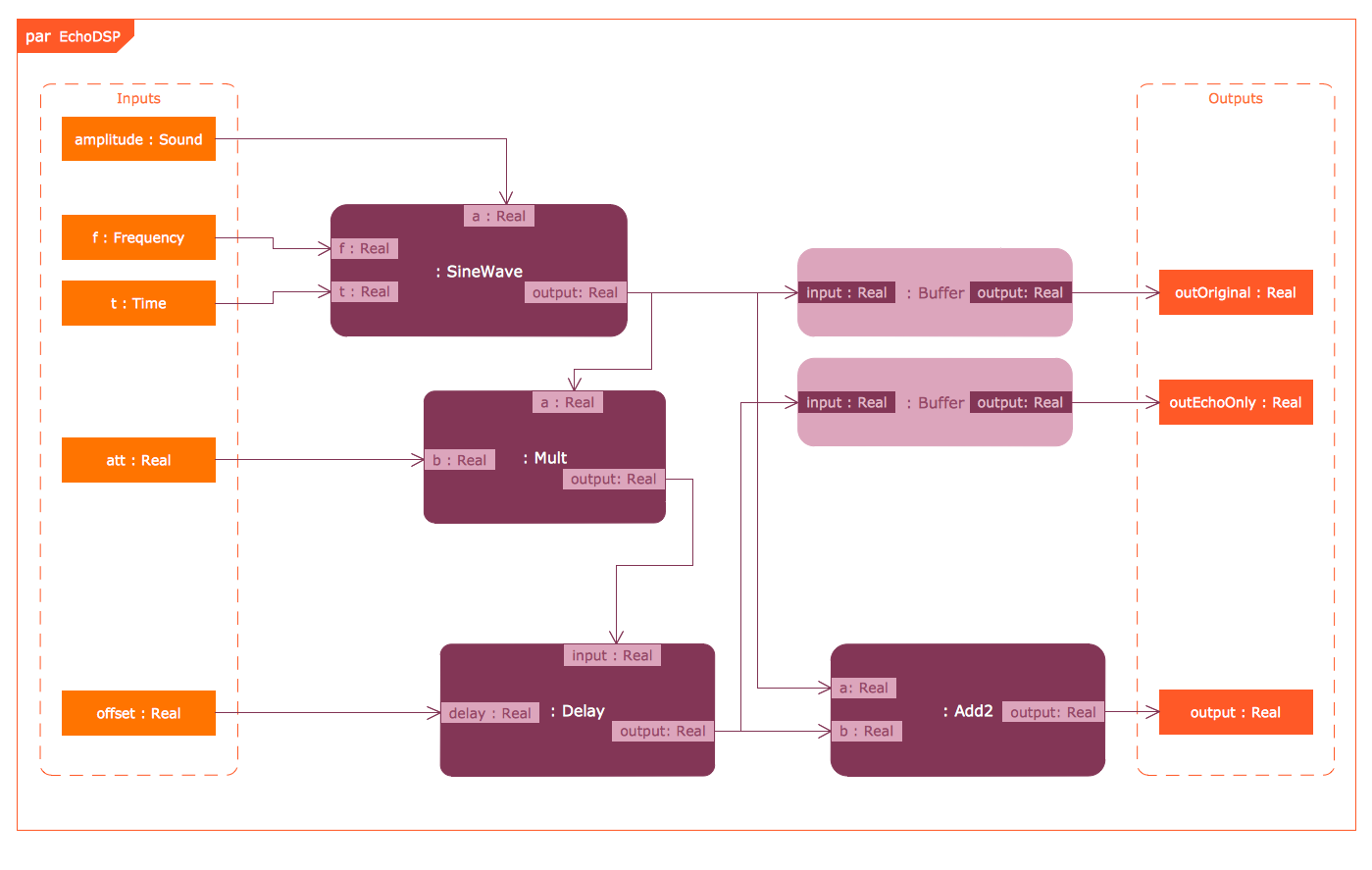
Example 7: SysML Parametric Diagram
This diagram was created in ConceptDraw DIAGRAM using the combination of libraries from the SysML solution. An experienced user spent 15 minutes creating this sample.
This example presents a SysML Parametric diagram constructed on the basis of a diagram from the "SysML Modelling Language explained" document published on the OMG Systems Modeling Language website. The Parametric diagrams are intended to conduct the system modeling and system analysis according to different system parameters, such as performance, reliability, and others. The analysis is realized by means of defining the constraint blocks. The block constraints are created as constraint properties in Parametric diagrams and are included to them along with other parameters. One can observe six constraint properties of type in a proposed diagram: SineWave, Mult, Delay, Add2, and Buffer; some of them are linked with each other. The inputs are represented in the green box at the left and the outputs in the blue one at the right. The system parameters are split between both of them and are associated with constraint property parameters. The connectors are used to link all system properties and constraint properties.

Example 8: SysML State Machine Diagram
This diagram was created in ConceptDraw DIAGRAM using the combination of libraries from the SysML solution. An experienced user spent 15 minutes creating this sample.
This sample offers a SysML State Machine diagram concentrated on the internal system changes and specifying its dynamic behavior. The sample was constructed in ConceptDraw DIAGRAM based on the “UML state diagram.png” Wikimedia Commons file. The State Machine diagrams have a wide spectrum of applications — from software development to business processes modeling, including the modeling of complex behavior systems. The traditional form of the State diagram with a common notation is preserved in this SysML diagram. The circles define the initial and end states, the rounded rectangles denote the states that an object pass in response to events during its life. The events that cause the changes of states are also depicted. So, the State Machine diagram is a kind of dynamic behavioral diagram that clearly represents the sequence of states of an object during its lifetime in response to occurred events, which may result in side-effects. The arrows connecting the state symbols describe the transitions between the corresponding states.

Inside


What I Need to Get Started
Both ConceptDraw DIAGRAM diagramming and drawing software and the SYSML solution can help creating the software engineering diagrams you need. The SYSML solution can be found in the Software Development area of ConceptDraw STORE application that can be downloaded from this site. Make sure that both ConceptDraw DIAGRAM and ConceptDraw STORE applications are installed on your computer before you get started.
How to install
After ConceptDraw STORE and ConceptDraw DIAGRAM are downloaded and installed, you can install the SYSML solution from the ConceptDraw STORE.

Start Using
To make sure that you are doing it all right, use the pre-designed symbols from the stencil libraries from the solution to make your drawings look smart and professional. Also, the pre-made examples from this solution can be used as drafts so your own drawings can be based on them. Using the samples, you can always change their structures, colors and data.

Systems Modeling Language (SysML) Diagrams
Originating as sub-dialect of Unified Modeling Language (UML), Systems Modeling Language (SysML) is to system engineers what UML is to software engineers. Smaller in content and simpler to learn than UML, the current version of SysML, 1.3, uses one of nine different diagram types to represent system models and interactions. Unlike UML, which focuses on standardizing the language used to describe software systems, SysML covers a broader range of systems, than can involve personnel, facilities, hardware or electrical components. What SysML has in common with its parent language is 7 of the 9 diagram forms, and the division of these diagrams into behavioral and structural types.
SysML behavioral diagrams
A behavioral diagram emphasizes the steps that must happen in the system being modeled. They show step-by-step the interaction and options available to the various components and actors of a process.
There are four SysML diagrams that describe the behavioral aspects of systems:
Activity diagrams
Activity diagrams break a workflow down into all possible steps, and show a flow of control or data. They are comprised of block shapes and connector lines elements that have inherent rules governing behavior and actions. System engineers can use them to specify process function independent of structure, without the use of partitions or 'swimlanes'.
A basic activity diagram made using ConceptDraw DIAGRAM, showing a temperature control system
Use Case diagrams
Participants in a system can have their involvement described as a series of use cases — a use case diagram presents those scenarios in their simplest form. Diagrams can be modified to show different levels of user interaction on the same system.

A use case scenario made with ConceptDraw DIAGRAM, showing different participants of the same system, and at what level they can influence behavior
Sequence diagrams
A sequence diagram shows messages passed between processes and systems, and the order in which they given. Objects are shown consecutively with 'lifelines', parallel descending vertical arrows that are intersected with horizontal lines carrying messages and actions performed in sequential time order.
A well known sequence diagram called the 'builder design pattern', made using ConceptDraw DIAGRAM
State Machine diagrams
System engineers use a state machine diagram to describe the state transitions of a system, and what actions it performs in response to events. Possibilities for system behavior depend upon which state it's in. This diagram uses notation to illustrate initial, final, and current states, with arrows being used to denote a transition.
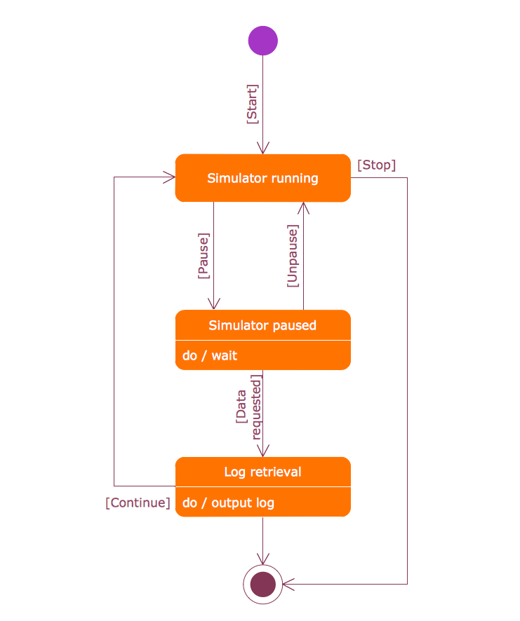
A state machine diagram produced using ConceptDraw DIAGRAM, to describe the states of a computer simulation
SysML structural diagrams
Structural diagrams exhibit the components that must be present for a system or process to work. They allow objects and components to be put into classes and hierarchies, with the option to add annotation that details attributes, operations and relationships within systems.
The four structural SysML diagrams contain 3 diagrams similar to their UML counterparts, with parametric diagrams as the lone original form:
Package diagrams
Package diagrams group all related objects or participants within a thematic package, and examine the dependencies between them. Packages can be arranged in layers or tiers, where layers represent the logical division of components into a hierarchical class structure, while tiers denote the physical grouping of objects through their geographical location.
Package diagrams show classes and possible interactions between them, produced to a high level of detail using ConceptDraw DIAGRAM
Block Definition and Internal Block Definition diagrams
These two diagram styles act as a compliment to each other, showing a system from a comparable level of detail, but from different perspectives. They both show the static structure of a system as a series of blocks connected via interfaces. Block definition diagrams show components only in terms of their input and output functions, disregarding the internal mechanisms that they resulted from. They also show how information and physical flows are supported using standard ports, flow ports and flow specifications.
ConceptDraw DIAGRAM allows you to create SysML block definition diagram to any degree of complexity
An internal block definition diagram takes a view of one of these individual blocks, and describes the parts that make up its internal structure; how these parts are connected to external interfaces and each other.
Parametric diagrams
A typical parametric diagram can be compared to a restricted form of internal block definition diagram. It shows the constraints of a particular block — these can be limitations on a certain performance aspect of a process — and what impact this has on their interactions with other blocks. They offer a chance to identify and articulate all possible constraints and rules of a system, which make them an invaluable tool for systems engineering trade studies.
Parametric diagrams made using ConceptDraw DIAGRAM help you see the limitation of a system
Requirements diagrams
Requirements diagrams somewhat eschew the two established categories, combining both structural and behavioral elements into the information presented. They list the requirements of each model element, and give definitions to the relationships arising from various states or the lifecycle timescale of the system.
Requirements diagrams can be made to a high level detail using ConceptDraw DIAGRAM
SysML throughout industry
Using diagramming as a technique to map system processes and describe functions allowing you to compare and contrast current state and possible future scenarios. Using SysML as a unified source of notation facilitates communication between other system engineers and stakeholders, creating diagrams that can be understood universally in intent and design. In terms of its application throughout industry, while UML is used almost solely to explain software system architecture, SysML can be applied across all forms of business in all its variations. Taking the automotive industry as an example, SysML diagrams can describe engine or electrical components inside the car, a sales transaction, or the procurement of spare parts and resources. It's this versatility that is so invaluable when communicating system design.
CS Odessa have long recognized the need for a comprehensive collection of modeling language notation for its diagramming software, ConceptDraw DIAGRAM. Through Solution Park, graphics libraries, samples and template have already been released for a number of UML solutions, giving software engineers a powerful set of tools for their system modeling requirements. Now the Systems Modeling Language Diagrams solution is set to enhance those capabilities even further, with 13 libraries consisting of all icons and graphic notations associated with the 9 diagram techniques. As is customary with a ConceptDraw solution, an accompanying online resource of video tutorials and help areas, as well as the samples and templates packed into the solution, means that any level of user can start designing systems on their own. The benefits to system engineers for putting their work through ConceptDraw DIAGRAM are the powerful design features that come into their own when process modeling — such as the intelligent connectors that manage their form dependent on your manipulation of drawing elements.
The SysML Diagrams solution is another indispensable drawing package for system engineer professionals, from CS Odessa.