- Electric and Telecom Plans Free
- Fire and Emergency Plans Free
- Floor Plans Free
- Plant Layout Plans Free
- School and Training Plans Free
- Seating Plans Free
- Security and Access Plans Free
- Site Plans Free
- Sport Field Plans Free
- Business Process Diagrams Free
- Business Process Mapping Free
- Classic Business Process Modeling Free
- Cross-Functional Flowcharts Free
- Event-driven Process Chain Diagrams Free
- IDEF Business Process Diagrams Free
- Logistics Flow Charts Free
- Workflow Diagrams Free
- ConceptDraw Dashboard for Facebook Free
- Mind Map Exchange Free
- MindTweet Free
- Note Exchange Free
- Project Exchange Free
- Social Media Response Free
- Active Directory Diagrams Free
- AWS Architecture Diagrams Free
- Azure Architecture Free
- Cisco Network Diagrams Free
- Cisco Networking Free
- Cloud Computing Diagrams Free
- Computer Network Diagrams Free
- Google Cloud Platform Free
- Interactive Voice Response Diagrams Free
- Network Layout Floor Plans Free
- Network Security Diagrams Free
- Rack Diagrams Free
- Telecommunication Network Diagrams Free
- Vehicular Networking Free
- Wireless Networks Free
- Comparison Dashboard Free
- Composition Dashboard Free
- Correlation Dashboard Free
- Frequency Distribution Dashboard Free
- Meter Dashboard Free
- Spatial Dashboard Free
- Status Dashboard Free
- Time Series Dashboard Free
- Basic Circle-Spoke Diagrams Free
- Basic Circular Arrows Diagrams Free
- Basic Venn Diagrams Free
- Block Diagrams Free
- Concept Maps Free
- Family Tree Free
- Flowcharts Free
- Basic Area Charts Free
- Basic Bar Graphs Free
- Basic Divided Bar Diagrams Free
- Basic Histograms Free
- Basic Line Graphs Free
- Basic Picture Graphs Free
- Basic Pie Charts Free
- Basic Scatter Diagrams Free
- Aerospace and Transport Free
- Artwork Free
- Audio, Video, Media Free
- Business and Finance Free
- Computers and Communications Free
- Holiday Free
- Manufacturing and Maintenance Free
- Nature Free
- People Free
- Presentation Clipart Free
- Safety and Security Free
- Analog Electronics Free
- Audio and Video Connectors Free
- Basic Circuit Diagrams Free
- Chemical and Process Engineering Free
- Digital Electronics Free
- Electrical Engineering Free
- Electron Tube Circuits Free
- Electronic Block Diagrams Free
- Fault Tree Analysis Diagrams Free
- GHS Hazard Pictograms Free
- Home Automation and Wiring Free
- Mechanical Engineering Free
- One-line Diagrams Free
- Power Сircuits Free
- Specification and Description Language (SDL) Free
- Telecom and AV Circuits Free
- Transport Hazard Pictograms Free
- Data-driven Infographics Free
- Pictorial Infographics Free
- Spatial Infographics Free
- Typography Infographics Free
- Calendars Free
- Decision Making Free
- Enterprise Architecture Diagrams Free
- Fishbone Diagrams Free
- Organizational Charts Free
- Plan-Do-Check-Act (PDCA) Free
- Seven Management and Planning Tools Free
- SWOT and TOWS Matrix Diagrams Free
- Timeline Diagrams Free
- Australia Map Free
- Continent Maps Free
- Directional Maps Free
- Germany Map Free
- Metro Map Free
- UK Map Free
- USA Maps Free
- Customer Journey Mapping Free
- Marketing Diagrams Free
- Matrices Free
- Pyramid Diagrams Free
- Sales Dashboard Free
- Sales Flowcharts Free
- Target and Circular Diagrams Free
- Cash Flow Reports Free
- Current Activities Reports Free
- Custom Excel Report Free
- Knowledge Reports Free
- MINDMAP Reports Free
- Overview Reports Free
- PM Agile Free
- PM Dashboards Free
- PM Docs Free
- PM Easy Free
- PM Meetings Free
- PM Planning Free
- PM Presentations Free
- PM Response Free
- Resource Usage Reports Free
- Visual Reports Free
- House of Quality Free
- Quality Mind Map Free
- Total Quality Management TQM Diagrams Free
- Value Stream Mapping Free
- Astronomy Free
- Biology Free
- Chemistry Free
- Language Learning Free
- Mathematics Free
- Physics Free
- Piano Sheet Music Free
- Android User Interface Free
- Class Hierarchy Tree Free
- Data Flow Diagrams (DFD) Free
- DOM Tree Free
- Entity-Relationship Diagram (ERD) Free
- EXPRESS-G data Modeling Diagram Free
- IDEF0 Diagrams Free
- iPhone User Interface Free
- Jackson Structured Programming (JSP) Diagrams Free
- macOS User Interface Free
- Object-Role Modeling (ORM) Diagrams Free
- Rapid UML Free
- SYSML Free
- Website Wireframe Free
- Windows 10 User Interface Free
Power Сircuits
Electrical diagrams, power circuits, and power supply system diagrams are implemented in the form of schematics, sketches, drawings, and graphic images. The diagrams in the form of graphic images are used for a wider audience, while diagrams and drawings are suitable for a narrower audience, for technical specialists in this field. Meanwhile, all diagrams are constructed according to the main principles of building electrical circuits prescribed in the regulatory documentation. The standards of the unified system of design documentation are applied in this field. These documents describe requirements for diagrams and drawings, design standards, describe symbols, their types and sizes, and the requirements for their use. They also define the rules for the arrangement, use of names and markings of the components.
Power Circuit Diagrams allow describing the sequence of connecting the electrical devices in power networks, indicating the location of power contacts and nodes, connections between nodes and electronic components that perform a connecting function. Power Circuits Diagrams allow describing the functions and principles of operation of electric components, their features in order to take them into account when creating electrical circuits. The diagrams allow designing electrical circuits, clearly mount all equipment, and in the future, in the event of a malfunction, it is easy to identify faults in the electrical circuit promptly eliminating them.
Typically, schematics of electrical circuits of different detailing are built for various purposes. These are general circuits, circuits of the power part, diagrams of primary circuits and low-current secondary circuits, linear circuits. Electrical diagrams are an essential part of the project documentation. The components of the circuit are displayed using the special graphical symbols, the connections are indicated using solid lines. The dashed lines are also used, for example, to show some additions.
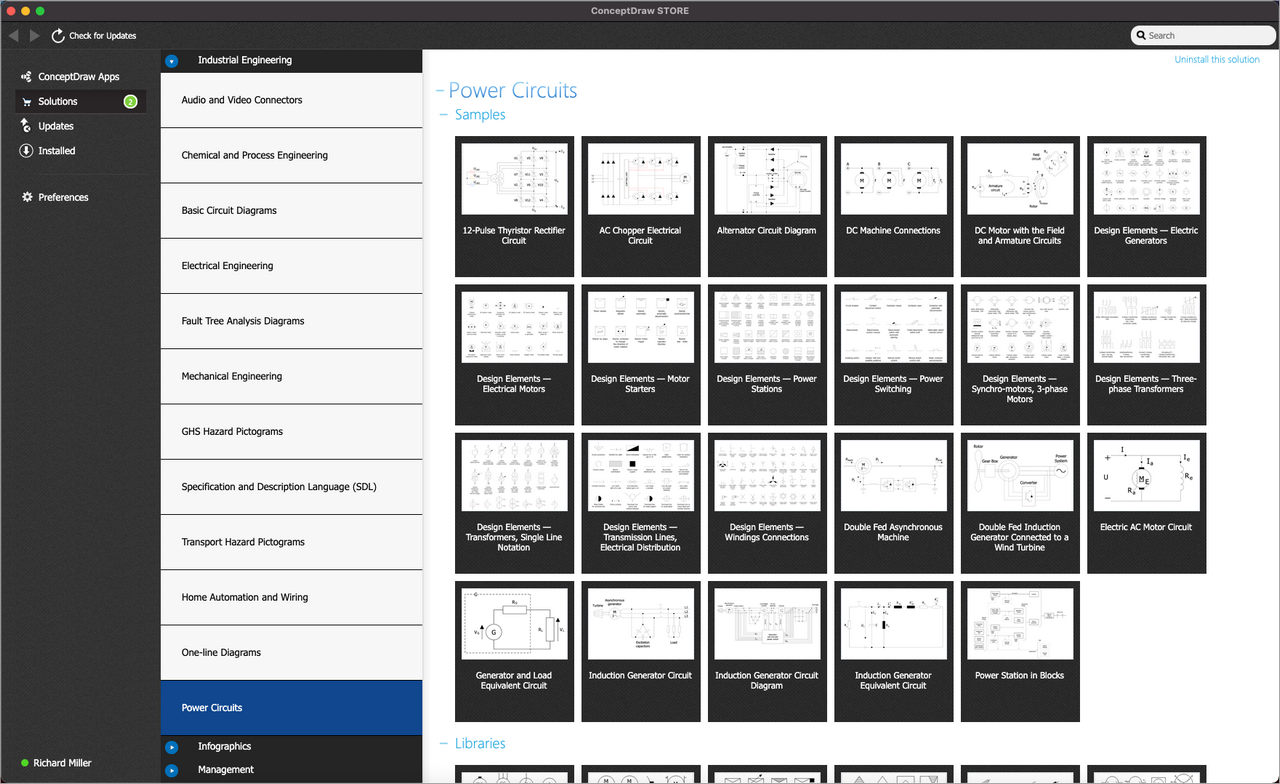
The Power Circuits solution for ConceptDraw DIAGRAM is designed for drawing power electrical circuits, power grids, power generation, transformation, transmission, and distribution systems. It includes a set of samples and a large number of generally accepted electrical circuit symbols that guarantee clarity and simple comprehension of diagrams. The electrical symbols of transformers, motor starters, power stations, electric generators, electrical motors, electrical distribution and power switching equipment, windings connections, transmission lines, and more are included. Use this solution to successfully create the Power Circuit Diagram of any complexity, display the functional parts of the electrical circuit and connections between them, design diagrams of electrical connections in substations. Explain the principles of operation of electrical and power mechanisms, one-phase and three-phase power generation, and create specifications of power electrical equipment with ease.
-
What I need to get started -
Solution Requirements - This solution requires the following products to be installed:
ConceptDraw DIAGRAM v18 - This solution requires the following products to be installed:
-
Support for this Solution -
Helpdesk
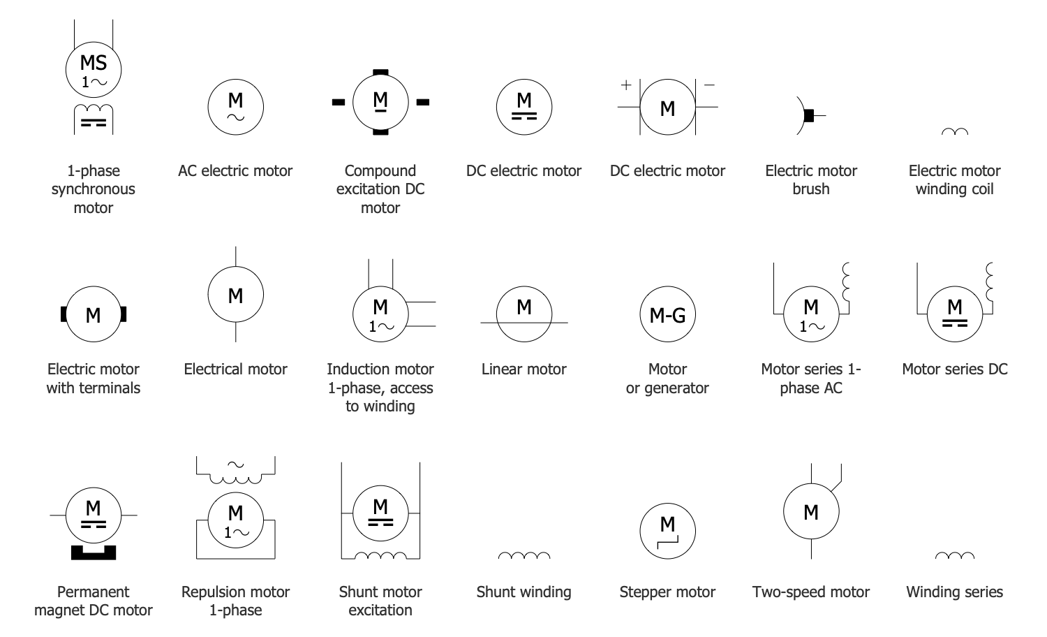
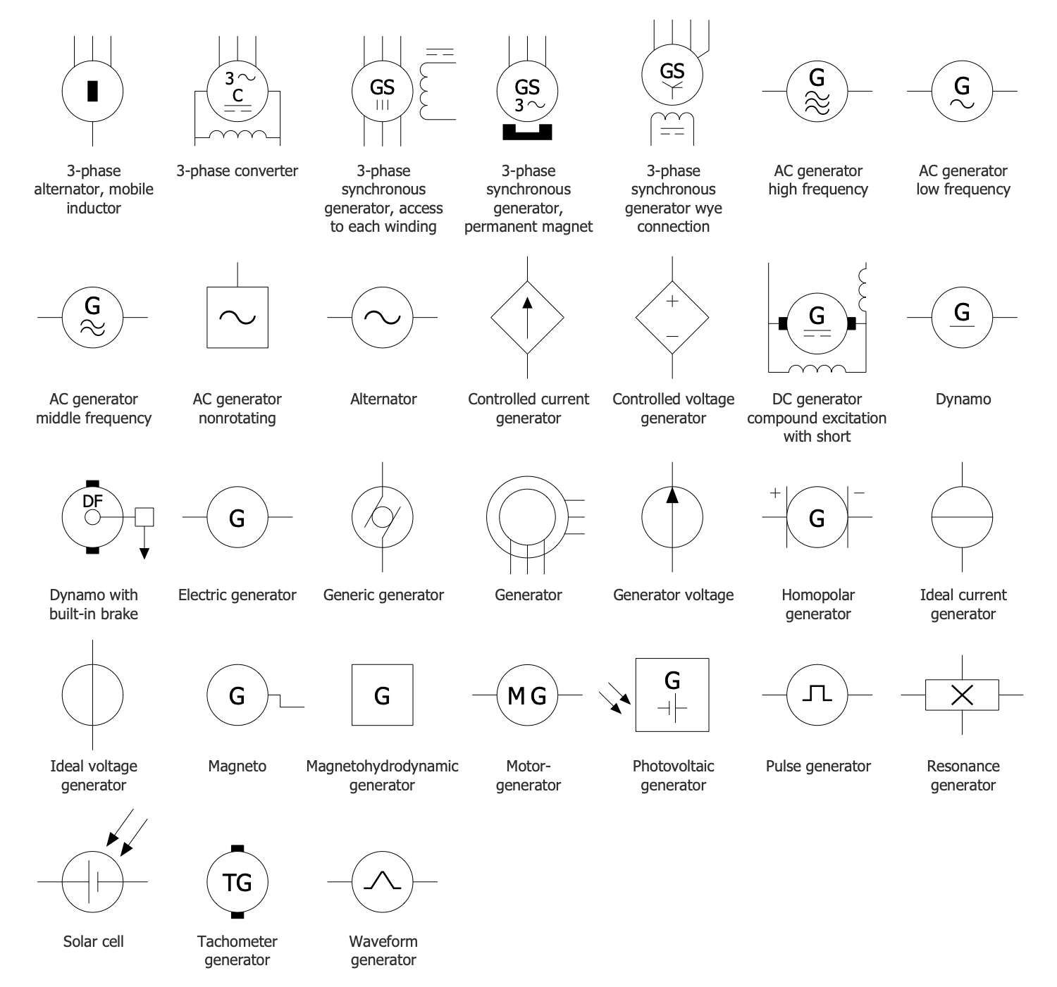
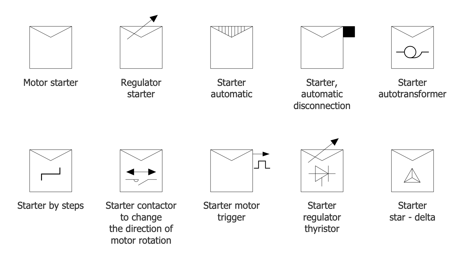
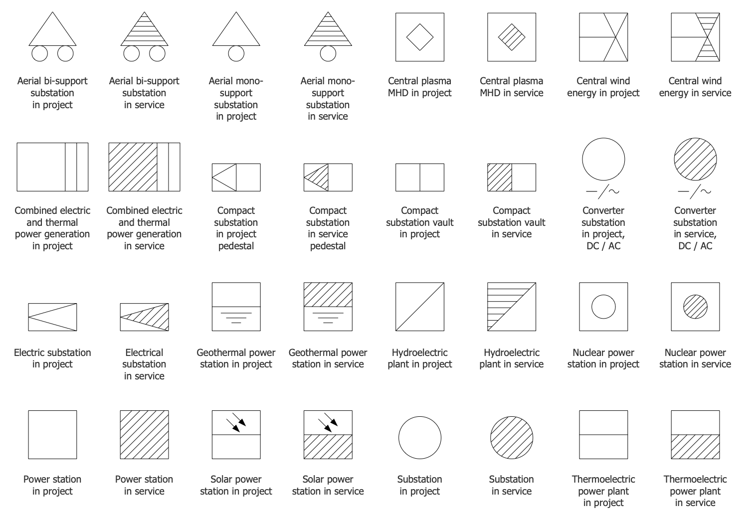
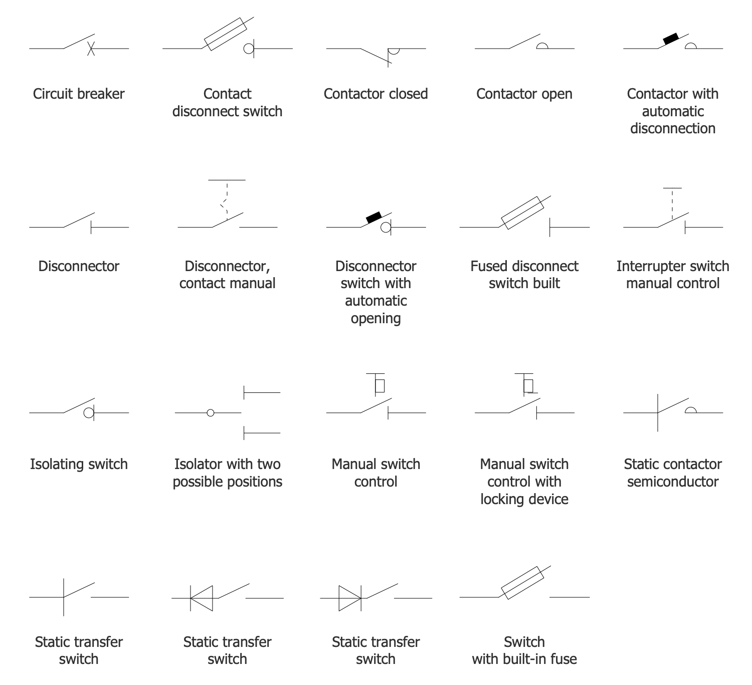
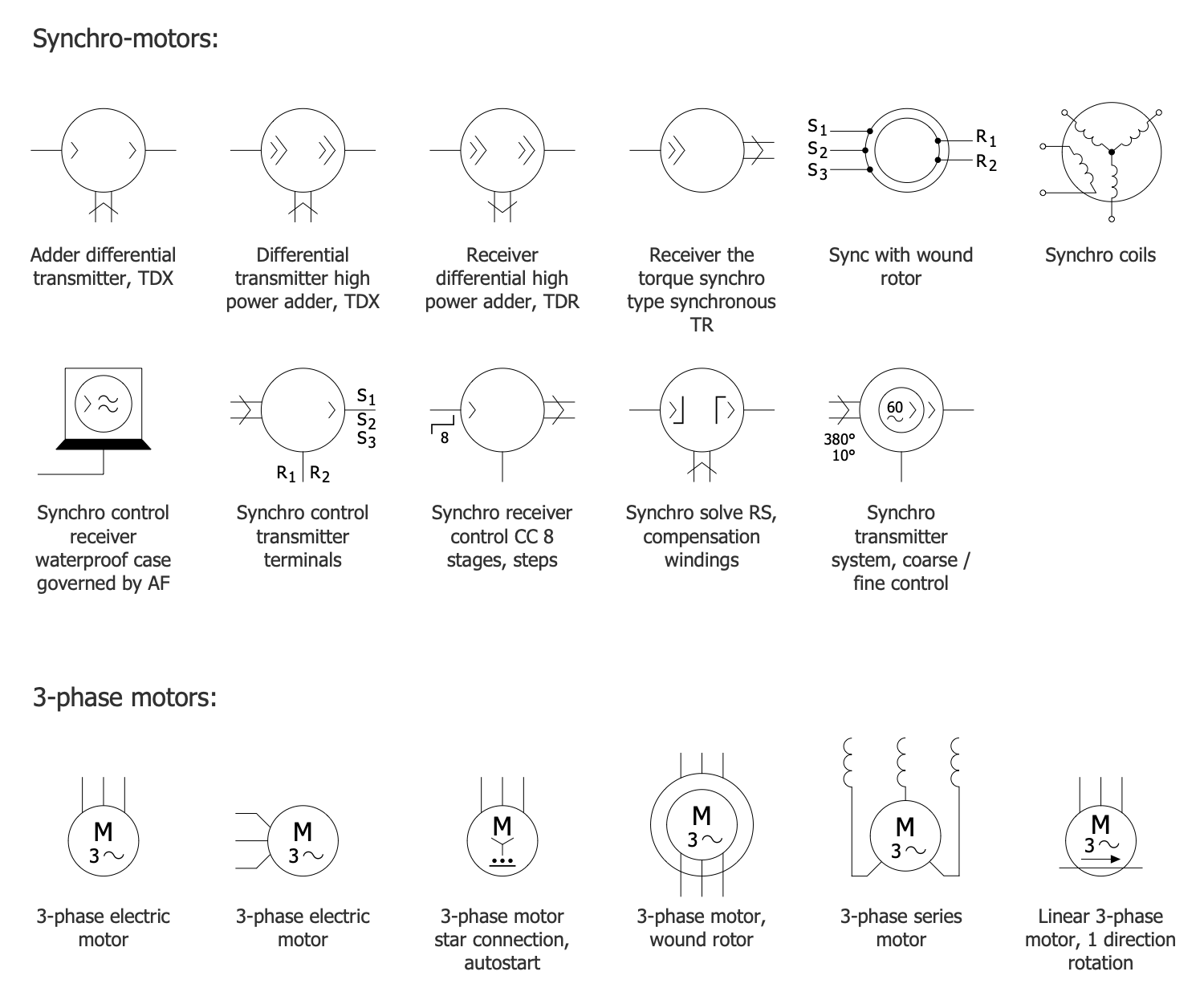
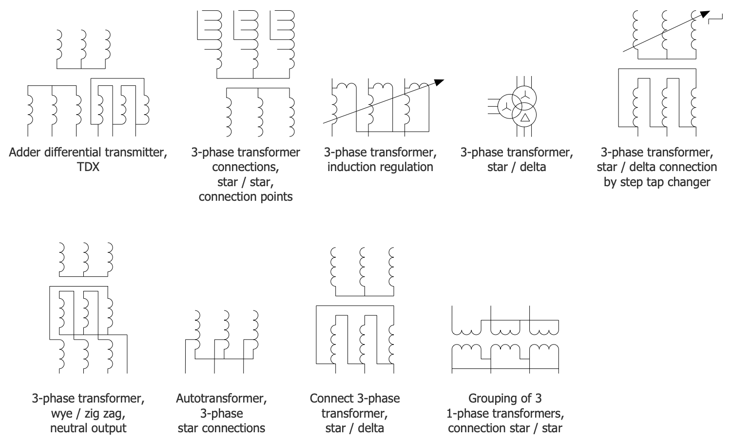
ConceptDraw Power Сircuits solution includes 10 libraries containing 255 symbols to the standards of the unified system of design documentation and 13 examples.
Design Elements — Electrical Motors
Design Elements — Electric Generators
Design Elements — Motor Starters
Design Elements — Power Stations
Design Elements — Power Switching
Design Elements — Synchro Motors 3-Phase Motors
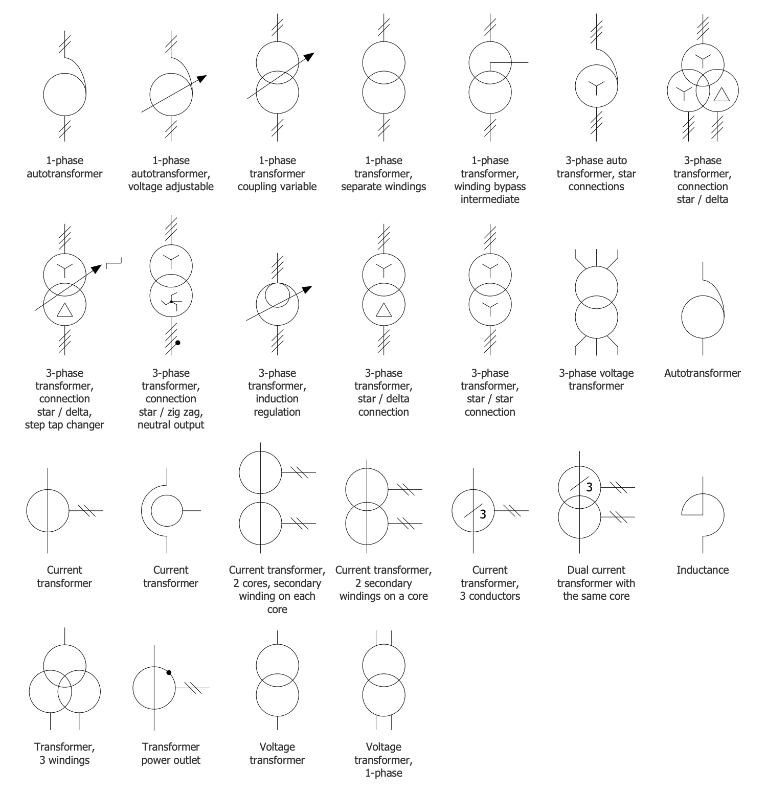
Design Elements — Three Phase Transformers
Design Elements — Transformers Single Line Notation
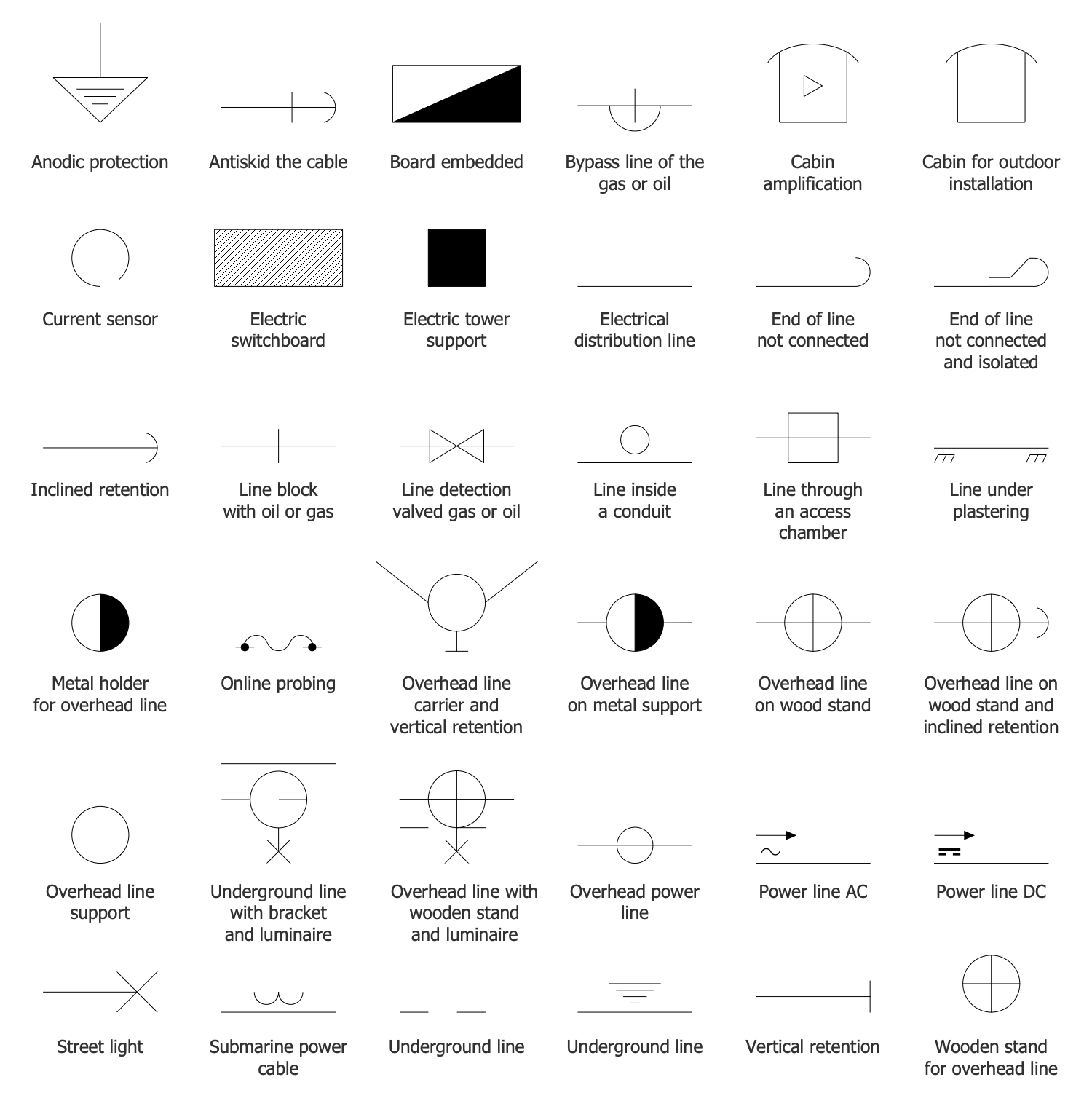
Design Elements — Transmission Lines Electrical Distribution
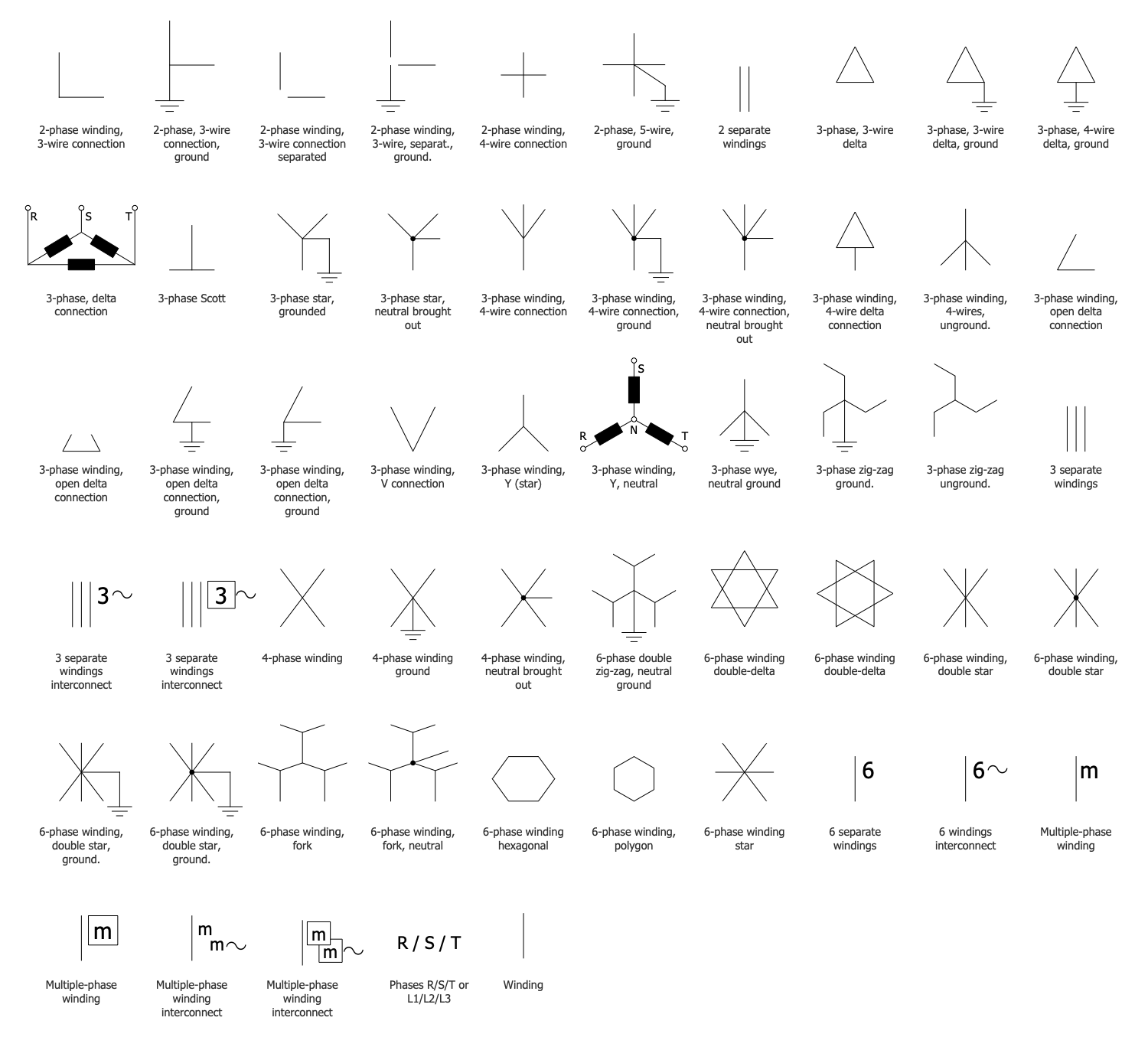
Design Elements — Windings Connections
Related News:
Examples
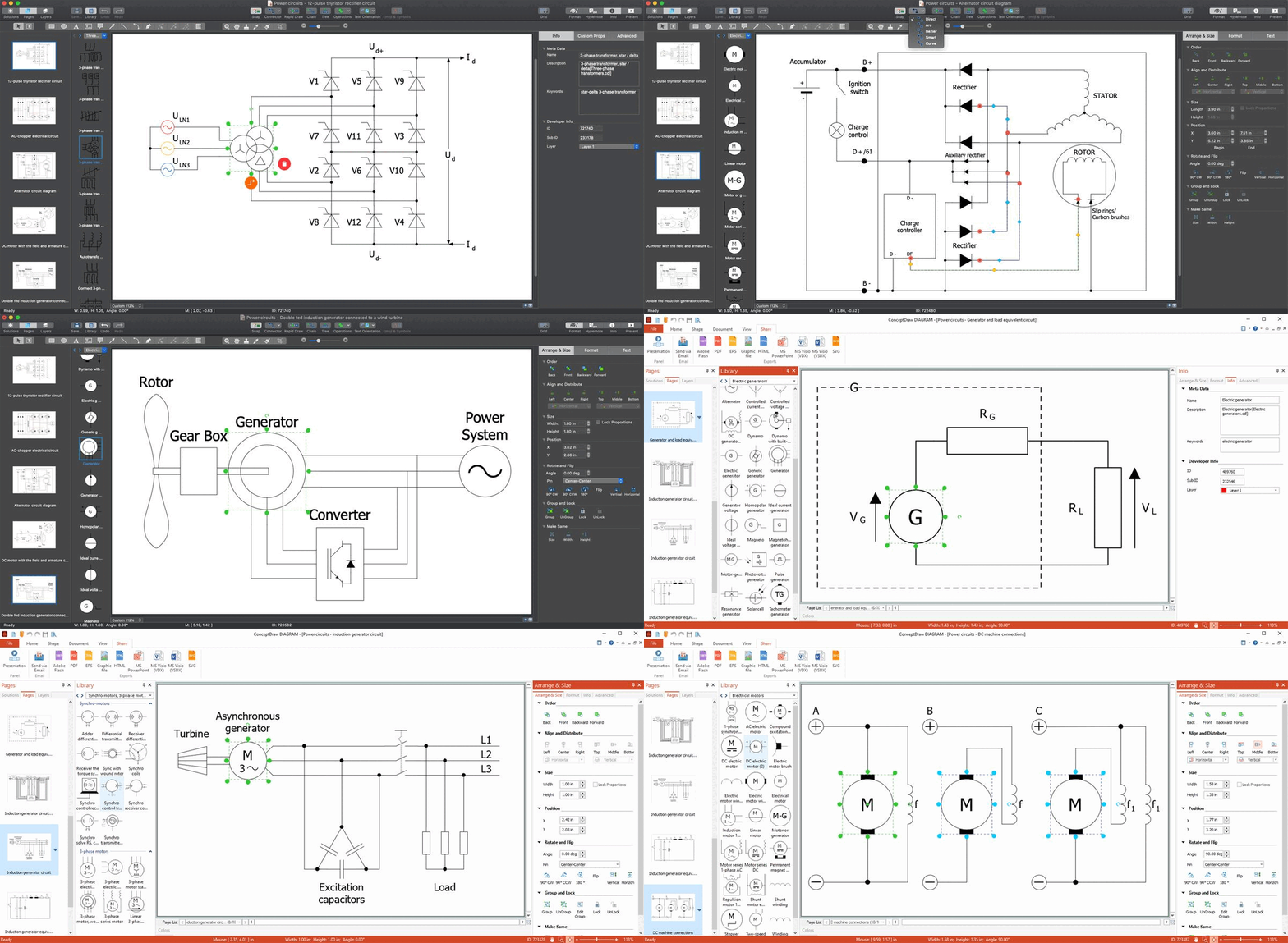
There are a few samples that you see on this page which were created in the ConceptDraw DIAGRAM application by using the Power Circuits solution. Some of the solution's capabilities as well as the professional results which you can achieve are all demonstrated here on this page.
All source documents are vector graphic documents which are always available for modifying, reviewing and/or converting to many different formats, such as MS PowerPoint, PDF file, MS Visio, and many other graphic ones from the ConceptDraw Solution Park or ConceptDraw STORE. The Power Circuits solution is available to all ConceptDraw DIAGRAM users to get installed and used while working in the ConceptDraw DIAGRAM diagramming and drawing software.
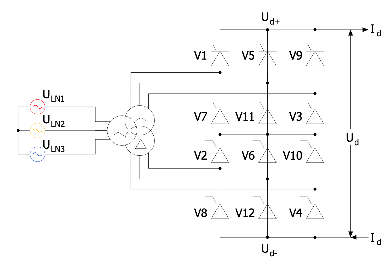
Example 1: 12-Pulse Thyristor Rectifier Circuit
This diagram was created in ConceptDraw DIAGRAM using a combination of libraries from the Power Circuits Solution. An experienced user spent 10 minutes creating this sample.
This sample Power Circuit Diagram shows a simple twelve-pulse thyristor rectifier circuit diagram with YD11 transformer connected. The rectifier included in this circuit is an electrical device used to convert AC to DC. This means converting a periodically varying current into a current flowing strictly in one direction. A twelve-pulse bridge connection consists of two six-pulse bridge circuits and is often used with rectifiers. These two six-pulse bridges are connected in series. The AC connections are powered by a power transformer. Transformers typically use two sets of secondary windings, usually connected in a star or delta connection. This provides a 30 degree phase shift between the two bridges. This circuit uses a three-phase transformer. Typically, six-pulse bridges create a lot of harmonic distortion in both AC and DC circuits. At the same time, the use of two six-pulse bridges inside a twelve-pulse bridge avoids this effect.
Example 2: AC Chopper Electrical Circuit
This diagram was created in ConceptDraw DIAGRAM using a combination of libraries from the Power Circuits Solution. An experienced user spent 10 minutes creating this sample.
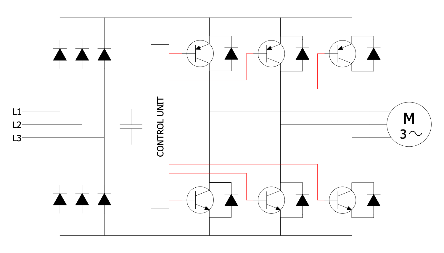
This Power Circuit Diagram sample shows an AC chopper electrical circuit. An AC chopper is a static power electronics device used as an AC converter. It is a highly demanded device owing to the fact that the current supplied to the load is often discontinuous. That's why it requires smoothing or a high switching frequency. An AC chopper is able to stabilize a system and avoid negative consequences. It is applied to vary the rms voltage across the load at a constant frequency, to increase or decrease the voltage level. The conversion process includes two stages and is quite high-cost. First, an AC chopper converts the fixed DC signal into an AC signal using an inverter. In turn, this AC signal is provided to a transformer and here, the step-up or step-down operations are performed over it. Further, the output from the transformer enters to a diode rectification unit. A DC signal is an output of a diode rectification unit.
Example 3: Alternator Circuit Diagram
This diagram was created in ConceptDraw DIAGRAM using a combination of libraries from the Power Circuits Solution. An experienced user spent 10 minutes creating this sample.
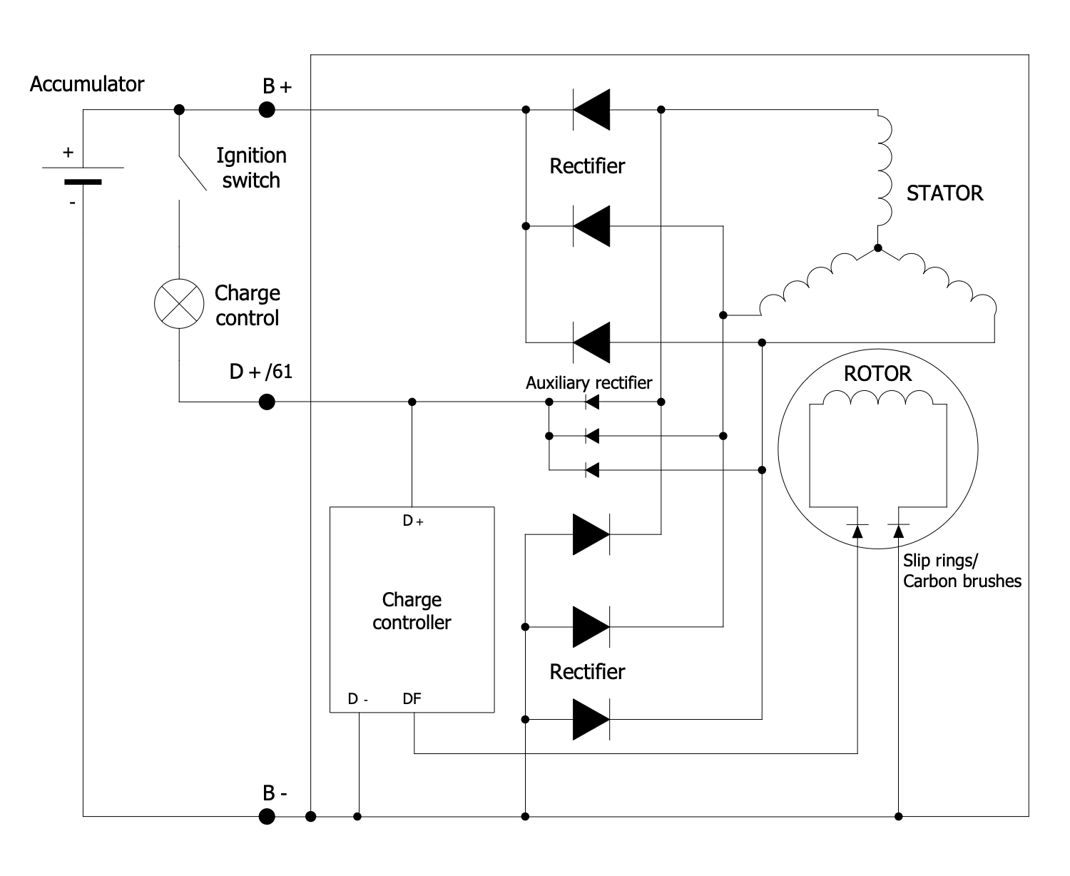
This example shows an alternator circuit diagram. The alternating current generating systems have been known since the 1830s when the magnetic induction of electric current was discovered. An alternator is an electric generator that converts mechanical energy to electrical energy in the form of AC. The modern alternators are used in automobiles to charge a battery and to power the electrical system at the running engine. Also, the alternators are applied in power stations driven by steam turbines and may use a permanent magnet for their magnetic field. The alternator from this diagram includes a rotating magnetic core called 'rotor' and stationary wire called 'stator'. A stationary set of conductors is wound in coils on the stator and the rotor turns within this set. The magnetic field of the rotating rotor produces the current in the stator. When moving relative to a magnetic field, a conductor develops an electromotive force in it.
Example 4: DC Machine Connections
This diagram was created in ConceptDraw DIAGRAM using a combination of libraries from the Power Circuits Solution. An experienced user spent 10 minutes creating this sample.
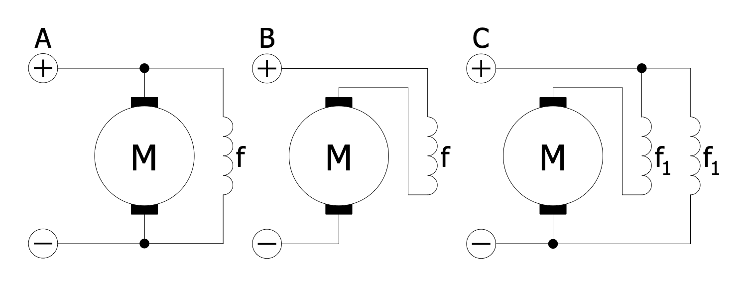
This Power Circuit Diagram sample shows the connector types for a DC machine. You can observe in detail how a field coil may be connected. There are three alternatives of electrical connections between the stator and rotor in DC electric machines (motors or generators): in shunt or parallel, in series, and in compound. The compound connections join the previous two types in different combinations. Each of these types offers the unique characteristics of speed and torque. Any rotary electrical motor is a DC motor and provides the conversion of direct current electrical energy into mechanical energy. It operates based on the forces produced by magnetic fields. Typically, it also has an internal electromechanical or electronic mechanism that gradually changes the direction of current in a part of the motor. Use the capabilities of the Power Circuits solution and included electrical symbols to design effectively your Power Circuit Diagrams of any complexity.
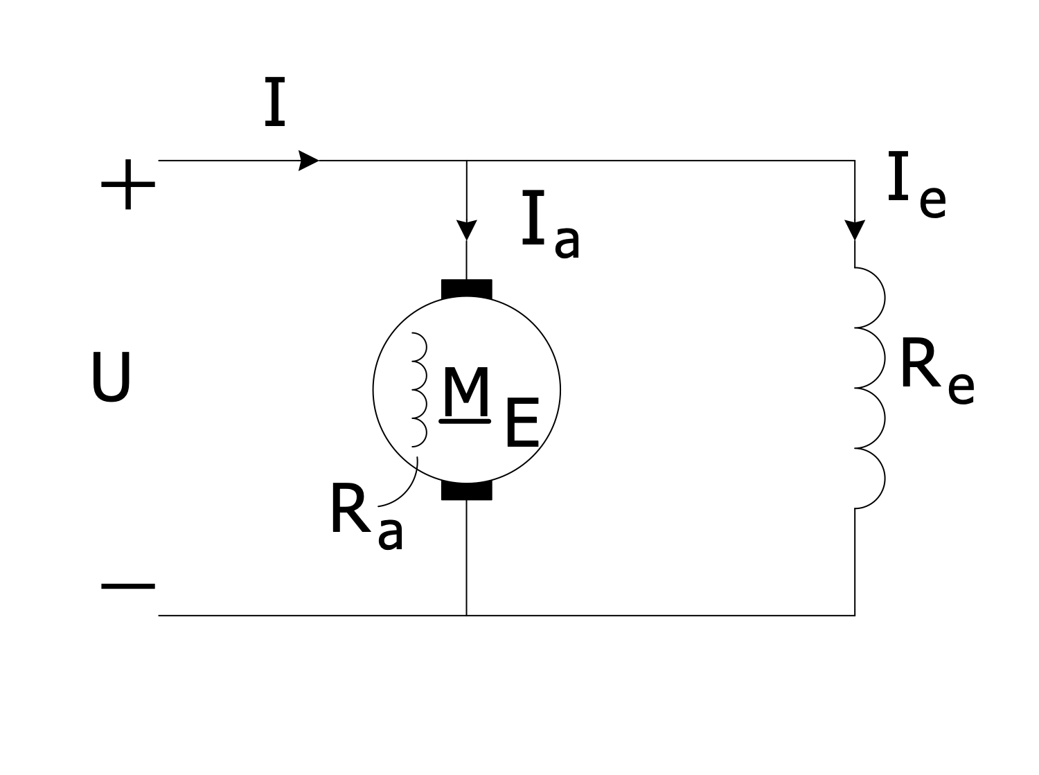
Example 5: DC Motor with the Field and Armature Circuits
This diagram was created in ConceptDraw DIAGRAM using a combination of libraries from the Power Circuits Solution. An experienced user spent 10 minutes creating this sample.
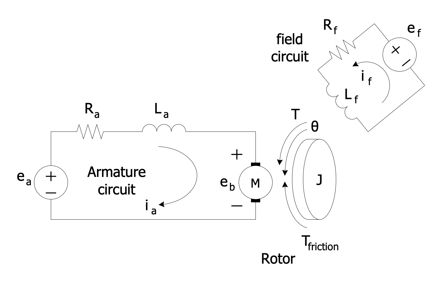
This Electrical Circuit Diagram sample shows a simple DC motor with two circuits — field and armature. The field circuit is always a constant current. It flows in the excitation winding of a rotating electric machine and creates a magnetic field. In this case, the rotor winding acts as an excitation winding. The armature is the winding of an electric machine that carries an alternating current. It is a conductor or a conductive coil. Depending on the type of electric machine, the armature is located on either the rotor or stator. The armature interacts with the magnetic field generated by magnets or electromagnets. It carries current across the field, converts electrical power to mechanical power, and creates shaft torque in a rotating machine. The relative motion of the armature and the field create an electromotive force (EMF). Being used as a generator, the armature EMF drives the armature current and movement of the shaft is converted to electrical power.
Example 6: Double Fed Asynchronous Machine
This diagram was created in ConceptDraw DIAGRAM using a combination of libraries from the Power Circuits Solution. An experienced user spent 10 minutes creating this sample.
This sample shows a double-fed asynchronous machine. It is a type of electric motor or electric generator. The double-fed machine is similar to AC electrical generator but has some additional features. It runs at higher or lower speeds than its natural synchronous speed. Due to this feature, they are successfully used in wind turbines with a variable speed. This makes it possible to flexibly respond to sudden changes in the wind. At the high gust of wind, the turbine can immediately speed up without causing wear or damages. The power taken from the wind gust is converted to useful electricity. A double-fed asynchronous machine contains two three-phase windings, one stationary and one rotating. They both are connected to equipment outside the generator. The first winding is connected to the output and produces 3-phase AC power. In turn, the second one is connected to 3-phase AC power at variable frequency.
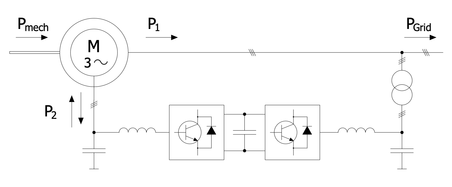
Example 7: Double Fed Induction Generator Connected to a Wind Turbine
This diagram was created in ConceptDraw DIAGRAM using a combination of libraries from the Power Circuits Solution. An experienced user spent 5 minutes creating this sample.
This sample circuit shows a Dual Powered Induction Generator (DFIG) connected to a wind turbine. The generators of this type are most commonly used, according to statistics about 80% of all worldwide used generators are DFIG. DFIG-based wind turbines possess the flexibility and ability to control active and reactive power. DFIG contains an induction generator with a multiphase wound rotor and a multiphase slip ring. The rotor windings are connected to the converter via slip rings and the stator ones are connected to the grid. The converter controls both the rotor and grid currents, and the stator's power fed to the grid. It controls the rotor field current frequency and the generator rotor speed. DFIG allows you to maintain a constant speed of the rotating magnetic field of the rotor and avoid strong vibrations. This helps to reduce the frequency of the rotor field current when mains faults cause it to accelerate.
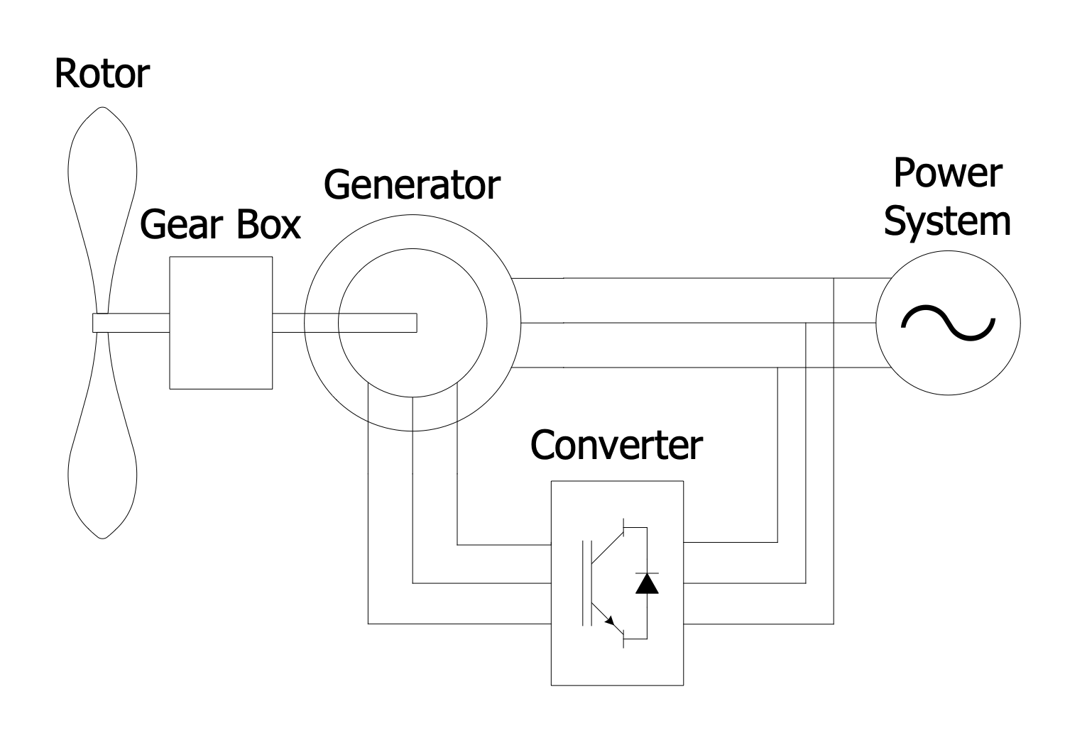
Example 8: Electric AC Motor Circuit
This diagram was created in ConceptDraw DIAGRAM using a combination of libraries from the Power Circuits Solution. An experienced user spent 5 minutes creating this sample.
This power circuit diagram sample shows an electric AC motor circuit. It is an electric motor driven by an alternating current and generating mechanical power, as a result. It allows creating a stable torque equal to the rated speed. An electric AC motor is simple to configure and handle, its work is based on magnetism. AC motor contains an outside stationary part — stator and inside rotating part — rotor. The stator consists of a wire loop, a solid metal axle, and freely moving metal parts. The rotor includes the coils producing a rotating magnetic field. Being supplied to the wire coil, an alternating current is turned into an electromagnet that produces the constantly changing magnetic field. In turn, based on the electromagnetism law, the magnetic field generates an electric current within the rotor. The rotor magnetic field may be also produced by DC electrical windings, magnets, or magnetic resistance.
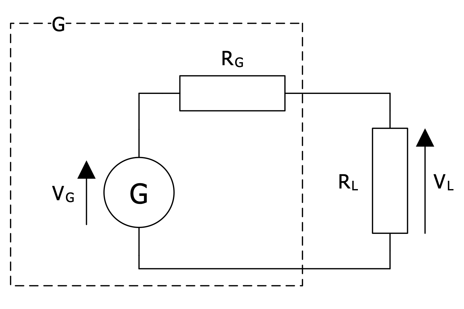
Example 9: Generator and Load Equivalent Circuit
This diagram was created in ConceptDraw DIAGRAM using a combination of libraries from the Power Circuits Solution. An experienced user spent 5 minutes creating this sample.
This Power Circuit Diagram sample shows a generator and load equivalent circuit. A generator is a common device in electrical engineering. It is used to convert mechanical power or motive power into electrical energy. This power is further used in an external circuit, in electric power grids. A generator is an ideal voltage source or an ideal current source. In general, a real electrical generator contains an ideal source and a resistor connected in parallel. There are many sources of mechanical energy: gas turbines, water turbines, steam turbines, wind turbines, internal combustion engines, and many more. The Internal resistance can range from high relative to the load to lower. An equivalent circuit is a simple circuit that retains all the electrical characteristics of a given circuit, but simplifies its analysis and various calculations, including resistance, impedance, transformer leakage reactance, etc. Usually, an equivalent circuit consists of linear passive elements.
Example 10: Induction Generator Circuit
This diagram was created in ConceptDraw DIAGRAM using a combination of libraries from the Power Circuits Solution. An experienced user spent 10 minutes creating this sample.
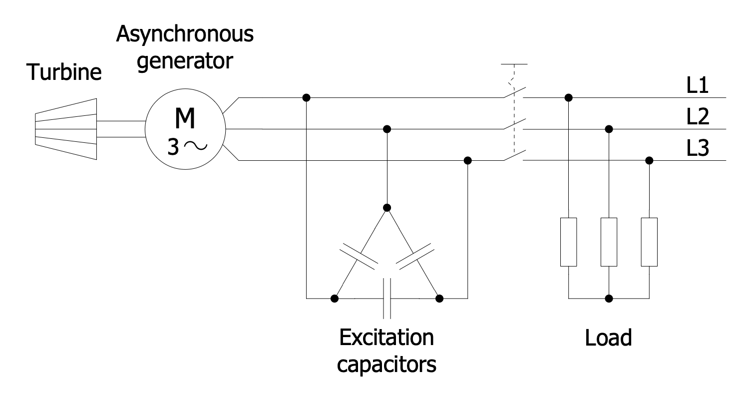
This diagram sample shows an induction or asynchronous generator. It is a type of alternating current electrical generator operated at the principles of induction motors. The configuration includes field capacitors and loads. The asynchronous generator is joined to the turbine, starts as a motor and draws the lagging reactive volt-amperes from the supply mains. The induction generator turns its rotor faster than synchronous speed. A generating torque is produced and is opposite to the direction of the rotor's rotation. As a result, the electric power is produced and delivered to the supply main. In this configuration, it is possible to use an induction machine or AC induction motor instead of a generator, without any modifications. The induction generators are commonly used in wind turbines and mini-hydropower plants. The power output depends on the amount of negative slip, rotor speed and motor rotation.
Example 11: Induction Generator Circuit Diagram
This diagram was created in ConceptDraw DIAGRAM using a combination of libraries from the Power Circuits Solution. An experienced user spent 15 minutes creating this sample.
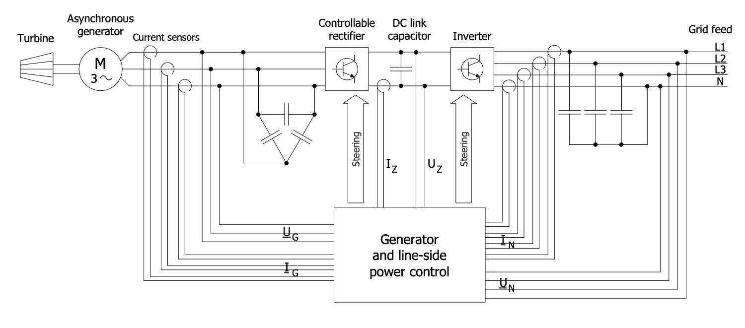
This sample shows a schematic of an inverter-coupled asynchronous generator. The connection to the network via inverters is advantageous for asynchronous generators. Two types of inverters are used: inverter with intermediate circuit and direct inverter. The input and output are connected directly to a direct inverter, without an intermediate circuit using semiconductor valves (thyristors). The output frequency can be changed and at the same time it is less than the input frequency. However, this type of inverter requires complex control and is therefore used much less frequently than DC link inverters. In the last ones, an insulated-gate bipolar transistor converter or a pulse converter is included. It is linked between the asynchronous generator and grid. The stator of the asynchronous generator is connected to the converter system. The output of the inverter feeds into the three-phase power network via an LC filter.
Example 12: Induction Generator Equivalent Circuit
This diagram was created in ConceptDraw DIAGRAM using a combination of libraries from the Power Circuits Solution. An experienced user spent 10 minutes creating this sample.
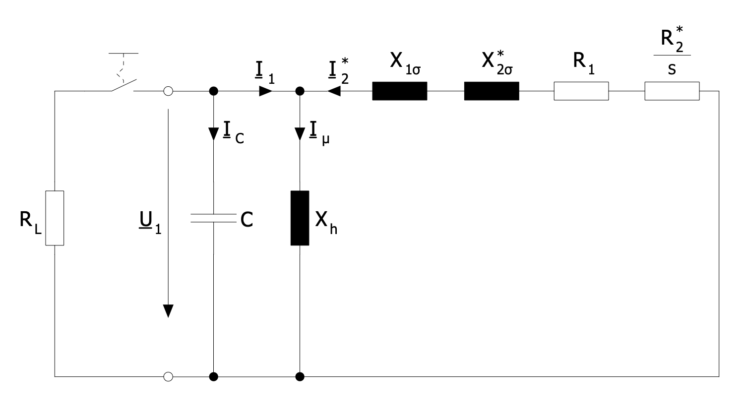
This diagram sample shows an equivalent circuit for an induction generator. An induction generator contains a rotor and a stator, and the rotor field always lags behind the stator field. That's why the induction generator always consumes reactive power and armature current supplied externally. The stator requires a significant magnetizing flux to induce rotor current. In this regard, the capacitors are included. They are charged with a DC source or by residual magnetism. Once the DC source is removed, the capacitors provide the magnetization current for the rotor. In turn, the rotor produces voltage. The induction generator saves a residual magnetism in the core right after it was stopped. Due to this fact, it can continue to spontaneously produce voltage and current for some time after stopping. Use the powerful Power Circuits solution tools and ready-made electrical circuit symbols to create asynchronous generators and asynchronous machines that act as generators in minutes.
Example 13: Power Station in Blocks
This diagram was created in ConceptDraw DIAGRAM using a combination of libraries from the Power Circuits Solution. An experienced user spent 15 minutes creating this sample.
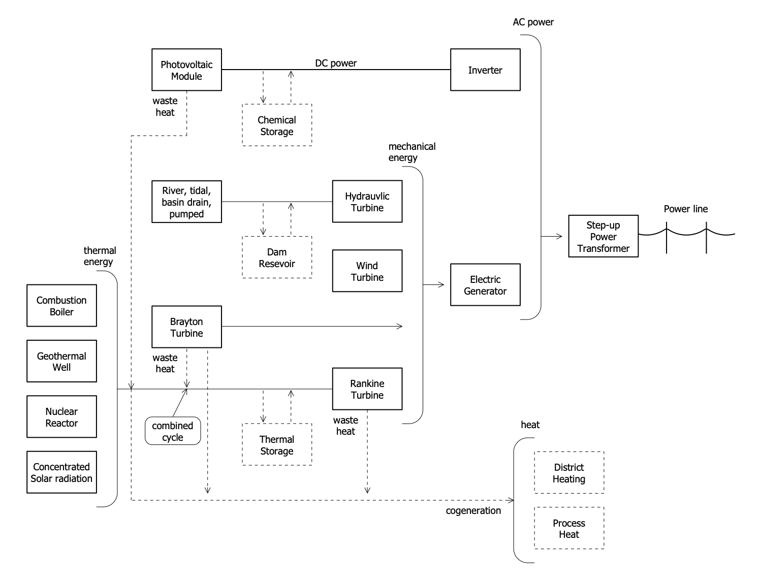
This Block Diagram sample shows different types of power stations. A power station also called a power plant is an industrial facility generating electric power and connected to an electrical grid. Typically, it contains electric generators (one or more) and a rotating machine converting mechanical power into three-phase electric power. Different kinds of energy sources are used to turn the generator. Most power plants generate electricity by burning various types of fossil fuels like coal, natural gas, oil. With regard to environmental and renewable energy sources, the main ones are solar, wind, wave, geothermal and hydroelectric power plants. The nuclear power also refers to the clean power sources. The transmission lines are commonly depicted by solid lines in Power Circuit Diagrams. The dotted lines in this diagram represent special additions such as combined cycle and cogeneration or additional storage. In addition, you can highlight important elements in the diagram so that they draw attention.
Inside
What I Need to Get Started
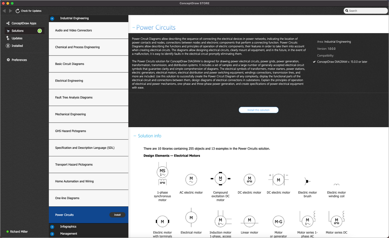
Both ConceptDraw DIAGRAM diagramming and drawing software and the Power Circuits solution can help creating the illustrations the technical documentation of an engineering projects you need. The Power Circuits solution can be found in the Industrial Engineering area of ConceptDraw STORE application that can be downloaded from this site. Make sure that both ConceptDraw DIAGRAM and ConceptDraw STORE applications are installed on your computer before you get started.
How to install
After ConceptDraw STORE and ConceptDraw DIAGRAM are downloaded and installed, you can install the Power Circuits solution from the ConceptDraw STORE.
Start Using
To make sure that you are doing it all right, use the pre-designed symbols from the stencil libraries from the solution to make your drawings look smart and professional. Also, the pre-made examples from this solution can be used as drafts so your own drawings can be based on them. Using the samples, you can always change their structures, colors and data.
