- Electric and Telecom Plans Free
- Fire and Emergency Plans Free
- Floor Plans Free
- Plant Layout Plans Free
- School and Training Plans Free
- Seating Plans Free
- Security and Access Plans Free
- Site Plans Free
- Sport Field Plans Free
- Business Process Diagrams Free
- Business Process Mapping Free
- Classic Business Process Modeling Free
- Cross-Functional Flowcharts Free
- Event-driven Process Chain Diagrams Free
- IDEF Business Process Diagrams Free
- Logistics Flow Charts Free
- Workflow Diagrams Free
- ConceptDraw Dashboard for Facebook Free
- Mind Map Exchange Free
- MindTweet Free
- Note Exchange Free
- Project Exchange Free
- Social Media Response Free
- Active Directory Diagrams Free
- AWS Architecture Diagrams Free
- Azure Architecture Free
- Cisco Network Diagrams Free
- Cisco Networking Free
- Cloud Computing Diagrams Free
- Computer Network Diagrams Free
- Google Cloud Platform Free
- Interactive Voice Response Diagrams Free
- Network Layout Floor Plans Free
- Network Security Diagrams Free
- Rack Diagrams Free
- Telecommunication Network Diagrams Free
- Vehicular Networking Free
- Wireless Networks Free
- Comparison Dashboard Free
- Composition Dashboard Free
- Correlation Dashboard Free
- Frequency Distribution Dashboard Free
- Meter Dashboard Free
- Spatial Dashboard Free
- Status Dashboard Free
- Time Series Dashboard Free
- Basic Circle-Spoke Diagrams Free
- Basic Circular Arrows Diagrams Free
- Basic Venn Diagrams Free
- Block Diagrams Free
- Concept Maps Free
- Family Tree Free
- Flowcharts Free
- Basic Area Charts Free
- Basic Bar Graphs Free
- Basic Divided Bar Diagrams Free
- Basic Histograms Free
- Basic Line Graphs Free
- Basic Picture Graphs Free
- Basic Pie Charts Free
- Basic Scatter Diagrams Free
- Aerospace and Transport Free
- Artwork Free
- Audio, Video, Media Free
- Business and Finance Free
- Computers and Communications Free
- Holiday Free
- Manufacturing and Maintenance Free
- Nature Free
- People Free
- Presentation Clipart Free
- Safety and Security Free
- Analog Electronics Free
- Audio and Video Connectors Free
- Basic Circuit Diagrams Free
- Chemical and Process Engineering Free
- Digital Electronics Free
- Electrical Engineering Free
- Electron Tube Circuits Free
- Electronic Block Diagrams Free
- Fault Tree Analysis Diagrams Free
- GHS Hazard Pictograms Free
- Home Automation and Wiring Free
- Mechanical Engineering Free
- One-line Diagrams Free
- Power Сircuits Free
- Specification and Description Language (SDL) Free
- Telecom and AV Circuits Free
- Transport Hazard Pictograms Free
- Data-driven Infographics Free
- Pictorial Infographics Free
- Spatial Infographics Free
- Typography Infographics Free
- Calendars Free
- Decision Making Free
- Enterprise Architecture Diagrams Free
- Fishbone Diagrams Free
- Organizational Charts Free
- Plan-Do-Check-Act (PDCA) Free
- Seven Management and Planning Tools Free
- SWOT and TOWS Matrix Diagrams Free
- Timeline Diagrams Free
- Australia Map Free
- Continent Maps Free
- Directional Maps Free
- Germany Map Free
- Metro Map Free
- UK Map Free
- USA Maps Free
- Customer Journey Mapping Free
- Marketing Diagrams Free
- Matrices Free
- Pyramid Diagrams Free
- Sales Dashboard Free
- Sales Flowcharts Free
- Target and Circular Diagrams Free
- Cash Flow Reports Free
- Current Activities Reports Free
- Custom Excel Report Free
- Knowledge Reports Free
- MINDMAP Reports Free
- Overview Reports Free
- PM Agile Free
- PM Dashboards Free
- PM Docs Free
- PM Easy Free
- PM Meetings Free
- PM Planning Free
- PM Presentations Free
- PM Response Free
- Resource Usage Reports Free
- Visual Reports Free
- House of Quality Free
- Quality Mind Map Free
- Total Quality Management TQM Diagrams Free
- Value Stream Mapping Free
- Astronomy Free
- Biology Free
- Chemistry Free
- Language Learning Free
- Mathematics Free
- Physics Free
- Piano Sheet Music Free
- Android User Interface Free
- Class Hierarchy Tree Free
- Data Flow Diagrams (DFD) Free
- DOM Tree Free
- Entity-Relationship Diagram (ERD) Free
- EXPRESS-G data Modeling Diagram Free
- IDEF0 Diagrams Free
- iPhone User Interface Free
- Jackson Structured Programming (JSP) Diagrams Free
- macOS User Interface Free
- Object-Role Modeling (ORM) Diagrams Free
- Rapid UML Free
- SYSML Free
- Website Wireframe Free
- Windows 10 User Interface Free
Vehicular Networking
Network engineering is an extensive area with a wide range of applications. Depending on the field of the application, network engineers design and realize the networks of different sizes and complexity - from the small networks to extensive and complex ones which cover wide territories. In latter case, it will be ideal to recourse to a specialized drawing software such as ConceptDraw DIAGRAM diagramming and vector drawing tool.
Vehicular networking is one of the advanced areas in a modern world, moreover the area with significant potential for further development. Vehicle communication systems can be considered such type of networks in which the roadside units and vehicles are the communicating nodes that share different information with each other. In terms of vehicular network, engineering and vehicle communications are developing multiple innovative applications for drivers along with passengers, devices and different Intelligent transportation systems with the objective of ensuring vehicle traffic control, traffic safety and traffic efficiency, for wireless data exchange between vehicles and road infrastructure, for optimization movement of vehicles, for receiving and transmission the safety warnings and traffic information, for coordination traffic flows and effective organizing movement of vehicles, drivers, pedestrians and passengers, as well as for delivering drivers the information on state of roads, traffic jams, road works, traffic restrictions, for registration the incidents and other adverse road conditions, alternative routes, locations of service stations, parking lots and fuel stations.
The Vehicular Networking solution extends the ConceptDraw DIAGRAM software functionality with specialized tools and pre-made vector objects in order to help network engineers visualize vehicular networks, develop smart transportation systems, design various types of vehicle network management diagrams, regional network diagrams, vehicular communication system diagrams, vehicular ad-hoc networks, vehicular delay-tolerant networks, and other network engineering schemes. This solution contains a set of libraries with a wide variety of predesigned objects, a large collection of samples, the global network templates and local vehicular networking templates, which will help you easily design various vehicular network diagrams for effective network engineering activity.
-
Install this solution Free -
What I need to get started -
Solution Requirements - This solution requires the following products to be installed:
ConceptDraw DIAGRAM v18 - This solution requires the following products to be installed:
-
Compatibility - Sonoma (14), Sonoma (15)
MS Windows 10, 11 - Sonoma (14), Sonoma (15)
-
Support for this Solution -
Helpdesk
There are 2 libraries containing 151 objects in the Vehicular Networking solution.
Design Element — Local Vehicular Networking

Design Element — Global Networks

Related News:
Five Solutions for ConceptDraw DIAGRAM, They Can Be Found in the Computer and Networks Area
New Vehicular Networking Solution: Adding a New Dimension to Diagramming
Examples
There are a few samples that you see on this page which were created in the ConceptDraw DIAGRAM application by using the Vehicular Networking solution. Some of the solution's capabilities as well as the professional results which you can achieve are all demonstrated here on this page.
All source documents are vector graphic documents which are always available for modifying, reviewing and/or converting to many different formats, such as MS PowerPoint, PDF file, MS Visio, and many other graphic ones from the ConceptDraw Solution Park or ConceptDraw STORE. The Vehicular Networking solution is available to all ConceptDraw DIAGRAM users to get installed and used while working in the ConceptDraw DIAGRAM diagramming and drawing software.
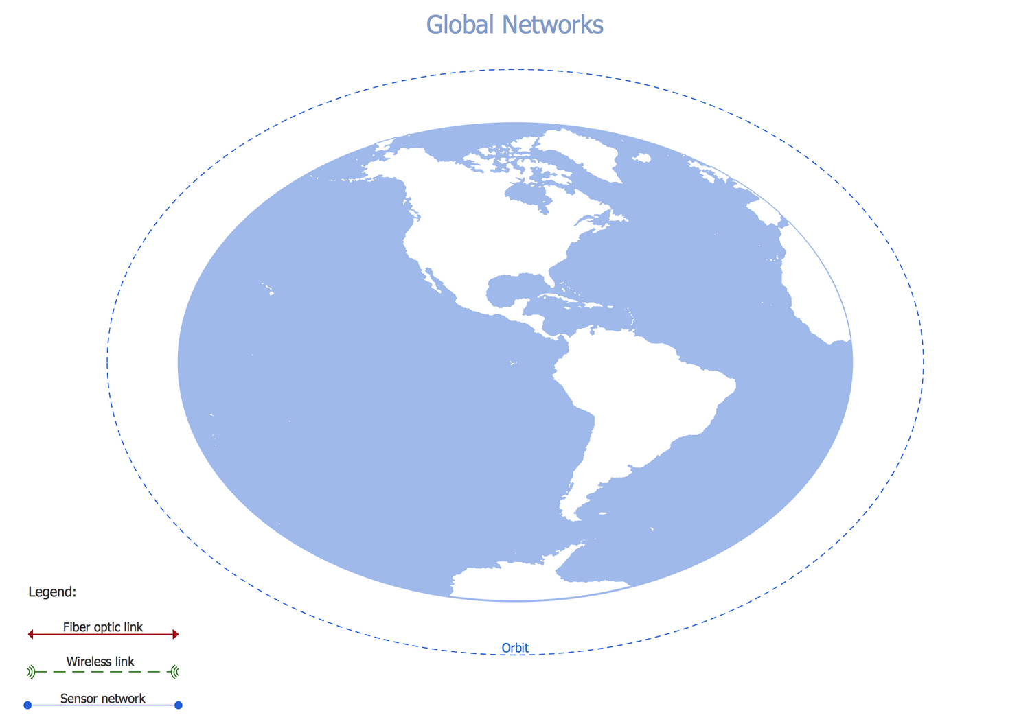
Example 1: Independent Regional Networks
This diagram was created in ConceptDraw DIAGRAM using the Global Networks library from the Vehicular Networking solution. An experienced user spent 15 minutes creating this sample.
This sample gives you an example of how you can display a range of networks, independent of each other, over a wide area. All relationships can be quickly understood using the information in the bottom left corner. The wired links, wireless links and sensor networks are marked in different ways on the diagram, this is especially useful when we have an extensive diagram and talk about networks located in different regions. The network you see on this diagram is an independent regional telematics network. The telematics is very popular now, it helps track vehicles regardless of their type, monitor their status, behavior, location and movements. Thanks to the Global Networks template included to the Vehicular Networking solution, this chart construction took only a few minutes. By taking this or any other ConceptDraw's template as a basis you can quickly start creating the chart of any complexity and complete it with the best result.

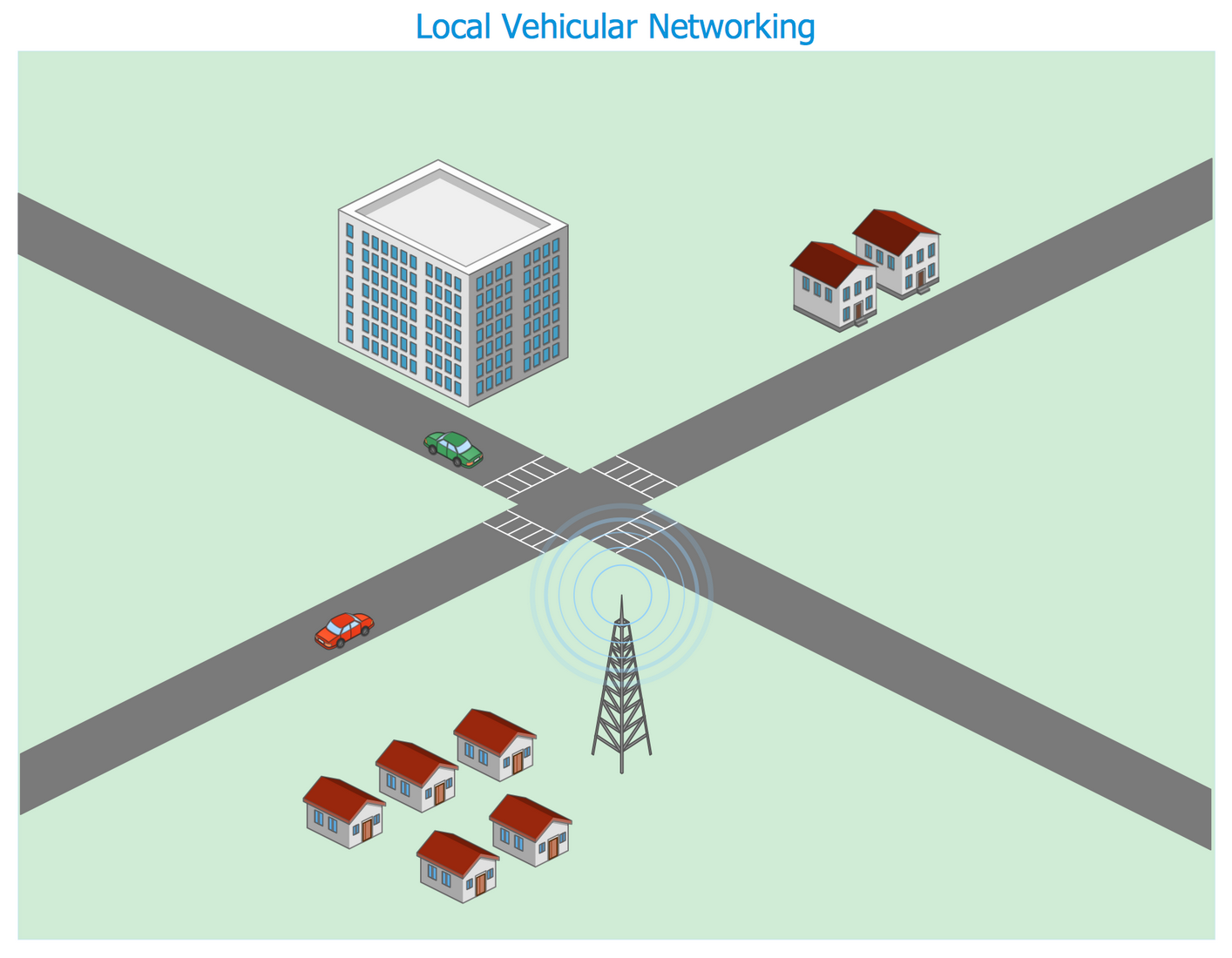
Example 2: Inter-Vehicle Communication Systems
This diagram was created in ConceptDraw DIAGRAM using the Local Vehicular Networking library from the Vehicular Networking solution. An experienced user spent 15 minutes creating this sample.
Network engineering is an umbrella term that includes various network-related areas of knowledge. Every day millions of network engineers need a convenient and simple in use application for designing their network schemes and for visualizing the vehicular networks. The job is done easily thanks to the ConceptDraw DIAGRAM software, extended with the Vehicular Networking solution. This Vehicular network diagram is designed in ConceptDraw DIAGRAM using as the base the "Inter-Vehicle Communication (IVC) systems" image published on a website of Department of Electrical and Computer Engineering of the Ohio State University. It illustrates the working principles of Inter-vehicle communication systems, which are the driver’ assistance systems that help them during the driving process, allow them to keep the absolute control over the traffic and road situation, and to exclude the traffic accidents. Besides, the Inter-vehicle communication systems can be used as for the linking vehicles between each other and for the communication with different infrastructure objects.

Example 3: Cooperative Vehicular Delay-Tolerant Network
This diagram was created in ConceptDraw DIAGRAM using the Local Vehicular Networking library from the Vehicular Networking solution. An experienced user spent 20 minutes creating this sample.
The Vehicular Networking solution from the ConceptDraw Solution Park gives you a comprehensive set of vector design elements and images to help in creating detailed diagrams of varied complexity. The scope for design is vast, from the worldwide views to the localized street scenes. This Vehicular network diagram sample represents the realization of a cooperative vehicular communication system, which is moreover delay-tolerant. Typically, the vehicular networks include two types of communicating nodes, such as the vehicles and roadside stations, and support both private and public data communications. When communicating with each other the nodes transfer the actual information about the current situation on the road, about road traffic and even offer the helpful safety warnings. All this information contributes to preventing the traffic congestions on the roads and also the road accidents. For the most part, the modern Intelligent Transport Systems (ITS) are developed including effective, thought-out and convenient vehicular communication systems.

Example 4: Intelligent Transportation System
This diagram was created in ConceptDraw DIAGRAM using the Local Vehicular Networking and Global Networks libraries from the Vehicular Networking solution. An experienced user spent 20 minutes creating this sample.
This sample visualizes the Intelligent transportation system (ITS) and was redesigned in the ConceptDraw DIAGRAM software on the base of illustration from the "Intelligent transportation system" post published at the "Technology New Here" blog. The Intelligent transportation system is a system that uses intellectual developments and innovative technologies, and applies them in a modeling of transport systems and in a regulation of traffic flows, in providing actual information about safety, which helps cope with the ever-increasing number of vehicles and traffic congestion, and ultimately contributes to the optimization and improvement the level of organization the road traffic, the road safety and precise interactions of its participants, also assists in enhancement the fuel efficiency. The Intelligent transportation systems are intended to be used for traffic management and different modes of transport, and have huge popularity due to the ability to give useful information helping make the road traffic run more efficiently and in a coordinated fashion.

Example 5: Wireless Mesh Networking
This diagram was created in ConceptDraw DIAGRAM using the Local Vehicular Networking library from the Vehicular Networking solution. An experienced user spent 15 minutes creating this sample.
This Vehicular network diagram sample illustrates a Wireless mesh network (WMN) and was created on the base of WMN illustration published on a website of Broadband Communications Research Group of the University of Waterloo in Canada, on the Ho Ting Cheng's blog. Wireless mesh network is a communications network created through the connection of wireless access points, which ensure the broadband wireless access, support the mobile computing and ubiquitous communications. The Wireless mesh networks can be constructed using the IEEE 802.16, IEEE 802.11, or LTE/LTE-A technologies, they also allow providing the access to the Internet and to peer-to-peer applications, and are popular in suburban and rural areas. Any ConceptDraw DIAGRAM user can easy illustrate a wireless mesh network configuration using the predesigned vector objects from the Local Vehicular Networking library developed and included to the ConceptDraw's Vehicular Networking solution. The ready solution's samples can also serve the good base for your diagrams.

Example 6: Cooperative Vehicular Delay-Tolerant Network Diagram
This diagram was created in ConceptDraw DIAGRAM using the Local Vehicular Networking library from the Vehicular Networking solution. An experienced user spent 15 minutes creating this sample.
This Vehicular network diagram sample illustrates a Wireless mesh network (WMN) and was created on the base of WMN illustration published on a website of Broadband Communications Research Group of the University of Waterloo in Canada, on the Ho Ting Cheng's blog. Wireless mesh network is a communications network created through the connection of wireless access points, which ensure the broadband wireless access, support the mobile computing and ubiquitous communications. The Wireless mesh networks can be constructed using the IEEE 802.16, IEEE 802.11, or LTE/LTE-A technologies, they also allow providing the access to the Internet and to peer-to-peer applications, and are popular in suburban and rural areas. Any ConceptDraw DIAGRAM user can easy illustrate a wireless mesh network configuration using the predesigned vector objects from the Local Vehicular Networking library developed and included to the ConceptDraw's Vehicular Networking solution. The ready solution's samples can also serve the good base for your diagrams.

Example 7: Automatic Vehicle Location
This diagram was created in ConceptDraw DIAGRAM using the Local Vehicular Networking library from the Vehicular Networking solution. An experienced user spent 15 minutes creating this sample.
This sample illustrates the vehicular network diagram representing a work of Automatic Vehicle Location (AVL) system, which is a specialized system defining the current location of a vehicle in a real-time, with the help of Global Positioning Satellite (GPS) receiver set in a given vehicle. Using the radio communications the data received from GPS receivers are transmitted to the transit center, where are used for different daily transactions and operations, or archived to be used or analyzed further. The AVL system is popular for use by large companies, which have in work more than 30 vehicles. The illustration for the "Automatic Vehicle Location: Rural Transit" article published on a website of Research and Innovative Technology Administration (RITA) of U.S. Department of Transportation (US DOT) was taken as the basis for this diagram. Redrawn in the ConceptDraw DIAGRAM software using its powerful vector drawing tools, this diagram is clear, attractive and easy for interpretation.

Example 8: Vehicular ad-hoc Network
This diagram was created in ConceptDraw DIAGRAM using the Local Vehicular Networking library from the Vehicular Networking solution. An experienced user spent 15 minutes creating this sample.
This Vehicular Network diagram sample represents the Vehicular ad-hoc Network (VANET) scheme that was designed having as the basis the image published on a "Security and Privacy in Location-based MANETs/VANETs" webpage, which is a part of the website of University of California and its Donald Bren School of Information and Computer Sciences. The Vehicular ad-hoc network (VANET) is an Intelligent transportation system (ITS) created according to the principles of Mobile ad-hoc network (MANET), using the vehicles as the mobile nodes and supposing construction of wireless network for data exchange between the cars and other vehicles. Thus, each vehicle from the VANET is used as a wireless router and provides the communication between vehicles typically on the distance from 100 to 300 meters. The use of VANET is most reasonable and popular when there are constructed the communications between police vehicles, fire vehicles, ambulances cars, or vehicles of some other services.

Example 9: Visible Light Communication
This diagram was created in ConceptDraw DIAGRAM using the Local Vehicular Networking library from the Vehicular Networking solution. An experienced user spent 15 minutes creating this sample.
This Vehicular network diagram sample depicts the application of Visible Light Communication (VLC) technology in a transport field and was designed on the base of illustration for the "LED Traffic Signals and Vehicle Lights for Optical Broadband Communications" post from the "Terranautix" blog. The Visible Light Communication is a technology, which allows the light source to transmit the lighting and additional information using the same light signal. At this, the light sources used in VCL has the optical spectrum from 400 THz until 800 THz. At a high frequency of attenuation and turning on the light, when the light is pulsing many times per second, the flashes become indistinguishable for the human eye, but at the same time they can carry a large informational load. This technology can use the fluorescent lamps or LEDs, but not any technology using a visible light signal refers to VLC because the information's transmission must be obligatorily indistinguishable by the human eye.

Example 10: California PATH Program Communications System
This diagram was created in ConceptDraw DIAGRAM using the Local Vehicular Networking library from the Vehicular Networking solution. An experienced user spent 15 minutes creating this sample.
This vehicular network diagram sample constructed in ConceptDraw DIAGRAM with the help of the Vehicular Networking solution represents the Intelligent Transportation System (ITS), which was initially developed for the California Partners for Advanced Transportation Technology (PATH) program and published on a website of Intelligent Transportations Systems Joint Program Office (ITS JPO) of the US Department of transportation. This Intelligent transportation system is a communication system applied in a transport sphere, which is especially effective when used in a combination with Computer-aided dispatch and scheduling (CADS) system or with Automatic vehicle location (AVL) system because such combination allows the transport dispatchers to receive in a voice or textual form the information about the location of the vehicles at the moment, as well as to promptly make the changes in the drivers’ itineraries, if it is necessary. At this, the updated information is instantly transmitted to the drivers allowing them to be always keeping the right course.

More Examples and Templates
Inside


What I Need to Get Started
Both ConceptDraw DIAGRAM diagramming and drawing software and the Vehicular Networking solution can help creating a variety of transportation networks, and their connections on a local or global scale. The Vehicular Networking solution can be found in the Computer and Networks area of ConceptDraw STORE application that can be downloaded from this site. Make sure that both ConceptDraw DIAGRAM and ConceptDraw STORE applications are installed on your computer before you get started.
How to Install
After ConceptDraw STORE and ConceptDraw DIAGRAM are downloaded and installed, you can install the Vehicular Networking solution from the ConceptDraw STORE.

Start using
To make sure that you are doing it all right, use the pre-designed symbols from the stencil libraries from the solution to make your drawings look smart and professional. Also, the pre-made examples from this solution can be used as drafts so your own drawings can be based on them. Using the samples, you can always change their structures, colors and data.

About
Benefits: The Vehicular Networking Solution allows you to swiftly develop conceptual diagrams for vehicular networking.
Objective: Provides a set of templates and objects to easily create conceptual diagrams of global and local vehicular networks.
Solution Purpose: To design, analyze and present vehicular network diagrams quickly and efficiently.
Intended For: Network engineers, network architects.
Products and Methods: A set of pre-designed objects, libraries, templates and samples that extends ConceptDraw DIAGRAM functionality, to help network engineers visualize vehicular networks.