- Electric and Telecom Plans Free
- Fire and Emergency Plans Free
- Floor Plans Free
- Plant Layout Plans Free
- School and Training Plans Free
- Seating Plans Free
- Security and Access Plans Free
- Site Plans Free
- Sport Field Plans Free
- Business Process Diagrams Free
- Business Process Mapping Free
- Classic Business Process Modeling Free
- Cross-Functional Flowcharts Free
- Event-driven Process Chain Diagrams Free
- IDEF Business Process Diagrams Free
- Logistics Flow Charts Free
- Workflow Diagrams Free
- ConceptDraw Dashboard for Facebook Free
- Mind Map Exchange Free
- MindTweet Free
- Note Exchange Free
- Project Exchange Free
- Social Media Response Free
- Active Directory Diagrams Free
- AWS Architecture Diagrams Free
- Azure Architecture Free
- Cisco Network Diagrams Free
- Cisco Networking Free
- Cloud Computing Diagrams Free
- Computer Network Diagrams Free
- Google Cloud Platform Free
- Interactive Voice Response Diagrams Free
- Network Layout Floor Plans Free
- Network Security Diagrams Free
- Rack Diagrams Free
- Telecommunication Network Diagrams Free
- Vehicular Networking Free
- Wireless Networks Free
- Comparison Dashboard Free
- Composition Dashboard Free
- Correlation Dashboard Free
- Frequency Distribution Dashboard Free
- Meter Dashboard Free
- Spatial Dashboard Free
- Status Dashboard Free
- Time Series Dashboard Free
- Basic Circle-Spoke Diagrams Free
- Basic Circular Arrows Diagrams Free
- Basic Venn Diagrams Free
- Block Diagrams Free
- Concept Maps Free
- Family Tree Free
- Flowcharts Free
- Basic Area Charts Free
- Basic Bar Graphs Free
- Basic Divided Bar Diagrams Free
- Basic Histograms Free
- Basic Line Graphs Free
- Basic Picture Graphs Free
- Basic Pie Charts Free
- Basic Scatter Diagrams Free
- Aerospace and Transport Free
- Artwork Free
- Audio, Video, Media Free
- Business and Finance Free
- Computers and Communications Free
- Holiday Free
- Manufacturing and Maintenance Free
- Nature Free
- People Free
- Presentation Clipart Free
- Safety and Security Free
- Analog Electronics Free
- Audio and Video Connectors Free
- Basic Circuit Diagrams Free
- Chemical and Process Engineering Free
- Digital Electronics Free
- Electrical Engineering Free
- Electron Tube Circuits Free
- Electronic Block Diagrams Free
- Fault Tree Analysis Diagrams Free
- GHS Hazard Pictograms Free
- Home Automation and Wiring Free
- Mechanical Engineering Free
- One-line Diagrams Free
- Power Сircuits Free
- Specification and Description Language (SDL) Free
- Telecom and AV Circuits Free
- Transport Hazard Pictograms Free
- Data-driven Infographics Free
- Pictorial Infographics Free
- Spatial Infographics Free
- Typography Infographics Free
- Calendars Free
- Decision Making Free
- Enterprise Architecture Diagrams Free
- Fishbone Diagrams Free
- Organizational Charts Free
- Plan-Do-Check-Act (PDCA) Free
- Seven Management and Planning Tools Free
- SWOT and TOWS Matrix Diagrams Free
- Timeline Diagrams Free
- Australia Map Free
- Continent Maps Free
- Directional Maps Free
- Germany Map Free
- Metro Map Free
- UK Map Free
- USA Maps Free
- Customer Journey Mapping Free
- Marketing Diagrams Free
- Matrices Free
- Pyramid Diagrams Free
- Sales Dashboard Free
- Sales Flowcharts Free
- Target and Circular Diagrams Free
- Cash Flow Reports Free
- Current Activities Reports Free
- Custom Excel Report Free
- Knowledge Reports Free
- MINDMAP Reports Free
- Overview Reports Free
- PM Agile Free
- PM Dashboards Free
- PM Docs Free
- PM Easy Free
- PM Meetings Free
- PM Planning Free
- PM Presentations Free
- PM Response Free
- Resource Usage Reports Free
- Visual Reports Free
- House of Quality Free
- Quality Mind Map Free
- Total Quality Management TQM Diagrams Free
- Value Stream Mapping Free
- Astronomy Free
- Biology Free
- Chemistry Free
- Language Learning Free
- Mathematics Free
- Physics Free
- Piano Sheet Music Free
- Android User Interface Free
- Class Hierarchy Tree Free
- Data Flow Diagrams (DFD) Free
- DOM Tree Free
- Entity-Relationship Diagram (ERD) Free
- EXPRESS-G data Modeling Diagram Free
- IDEF0 Diagrams Free
- iPhone User Interface Free
- Jackson Structured Programming (JSP) Diagrams Free
- macOS User Interface Free
- Object-Role Modeling (ORM) Diagrams Free
- Rapid UML Free
- SYSML Free
- Website Wireframe Free
- Windows 10 User Interface Free
One-line Diagrams
One-line Diagram or Single-line Diagram is a high-level schematic diagram developed for power engineering. It shows a power-related system in a simple way and allows studying a power flow. One-line Diagrams depict the parts and devices composing the systems and the course of an electric circuit or several circuits. They show the power flow paths between objects in the system and how incoming power is distributed to equipment.
One-line Diagram depicts a three-phase power system, however in common one conductor is symbolically shown in the diagram. It's possible because all three phases are similar to each other. Due to this fact, the diagrams are called "One-line Diagrams". The single lines and unique graphical symbols are used to depict different electrical elements in One-line Diagrams. Among them there are the electrical elements for conductors, transformers, capacitors, circuit breakers, and more.
One-line Diagram is a powerful way to display key information about a power system, its topology, installed equipment, working principles. It is a basic guide to building, maintaining and repairing a power system, planning and executing interlocking and tagging operations. Being a simple schematic One-line Diagram allows displaying some non-electrical information in addition to the electrical one, for example, economical data.
One-line Diagram is a reference to establish safe work conditions at the electricity distribution stations and other industries. It allows planning the correct and safe turning on/off the current in a circuit. One-line Diagram helps to envisage the installation of circuit breakers to interrupt the current flow when a fault is detected. It also allows you to think over and implement protection against accidental voltage return after the system is de-energized.
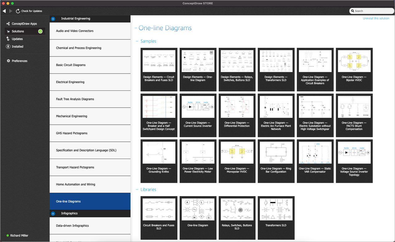
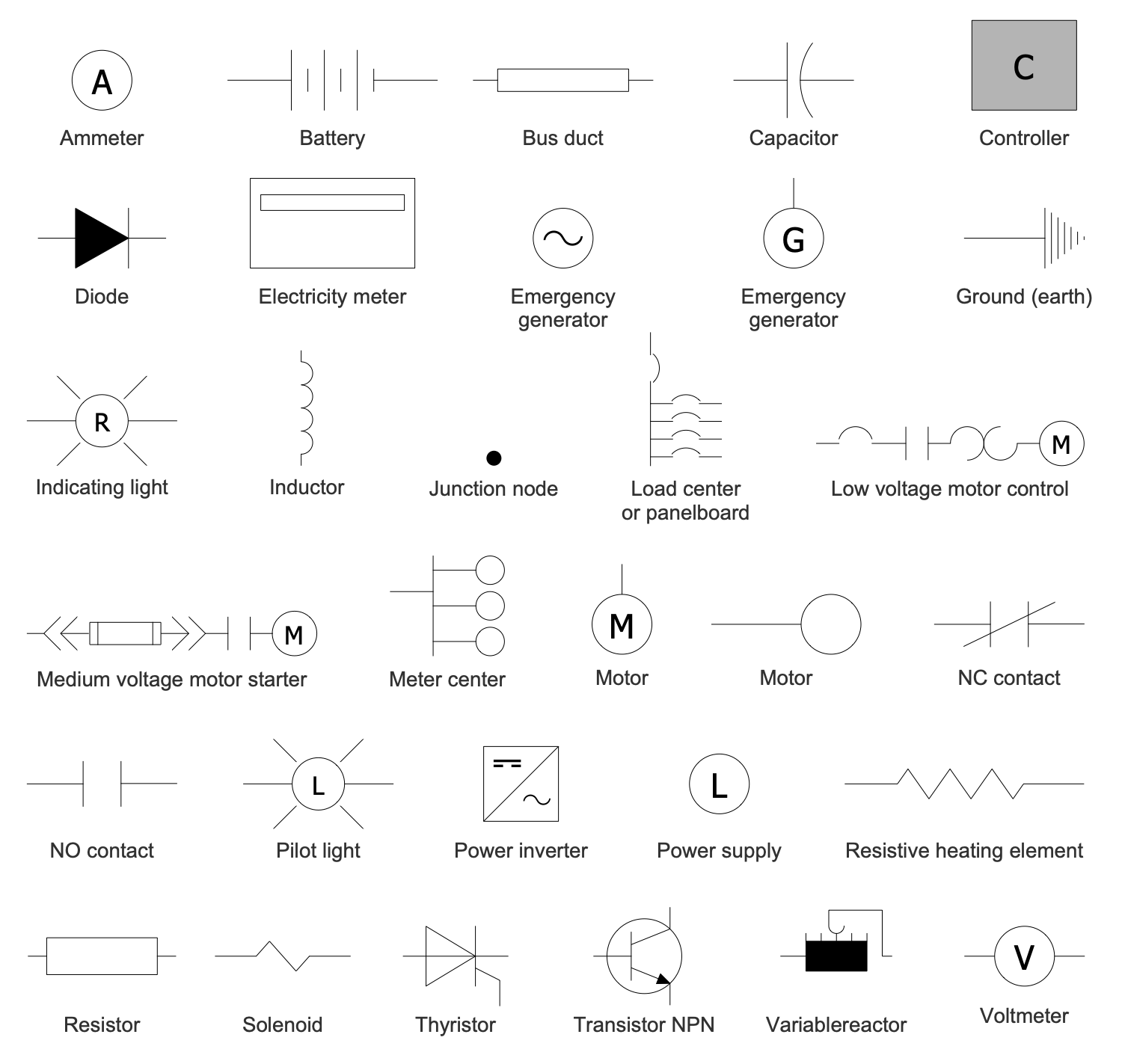
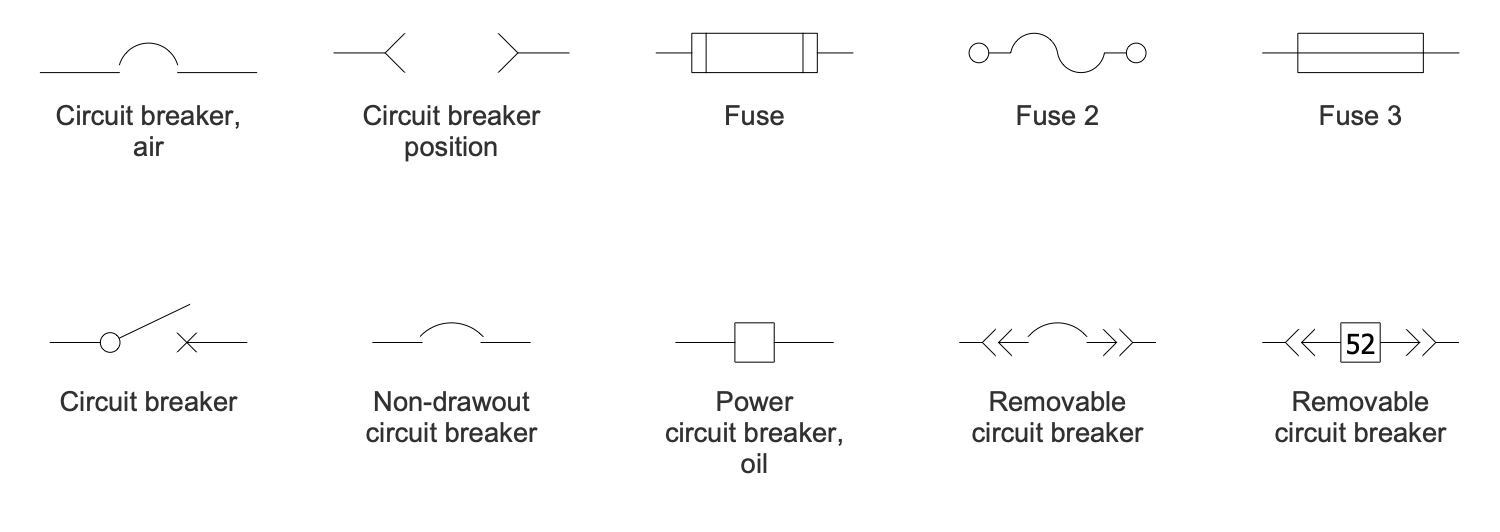
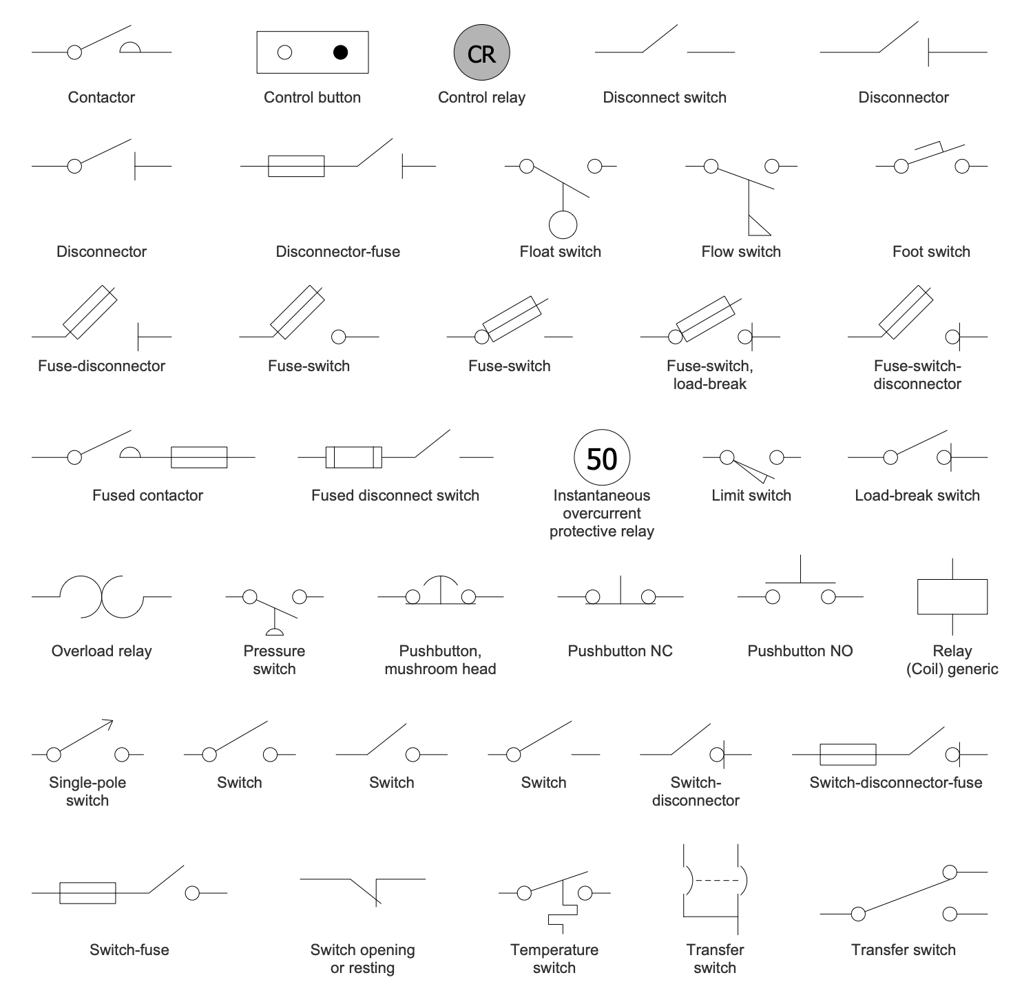
One-line Diagrams solution for ConceptDraw DIAGRAM is a powerful electrical engineering tool to develop precise and detailed One-line Diagram, Single-line Diagram, Electrical Diagram. This solution supplies the ConceptDraw DIAGRAM users with a wide set of vector libraries with special icons and electrical symbol elements for one-line drawing and electrical engineering diagram design including resistors, capacitors, circuit breakers, fuses, switches, transformers, batteries, inverters, controllers, and other power supply equipment. It includes a large collection of samples of One-line Diagrams illustrating high-voltage and low-voltage systems, different electrical configurations and topologies, transmission systems, application of circuit breakers, protection electrical equipment, etc. This solution is perfect for all power-related workers, engineers, electricians, and other professionals working in power engineering and energy industries.
-
What I need to get started -
Solution Requirements - This solution requires the following products to be installed:
-
Helpdesk
ConceptDraw One-line Diagrams solution includes 4 stencil libraries containing 116 industry-standard icons and electrical symbols and 14 examples.
Design Elements — One-Line Diagram
Design Elements — Circuit Breakers and Fuses SLD
Design Elements — Relays Switches Buttons SLD
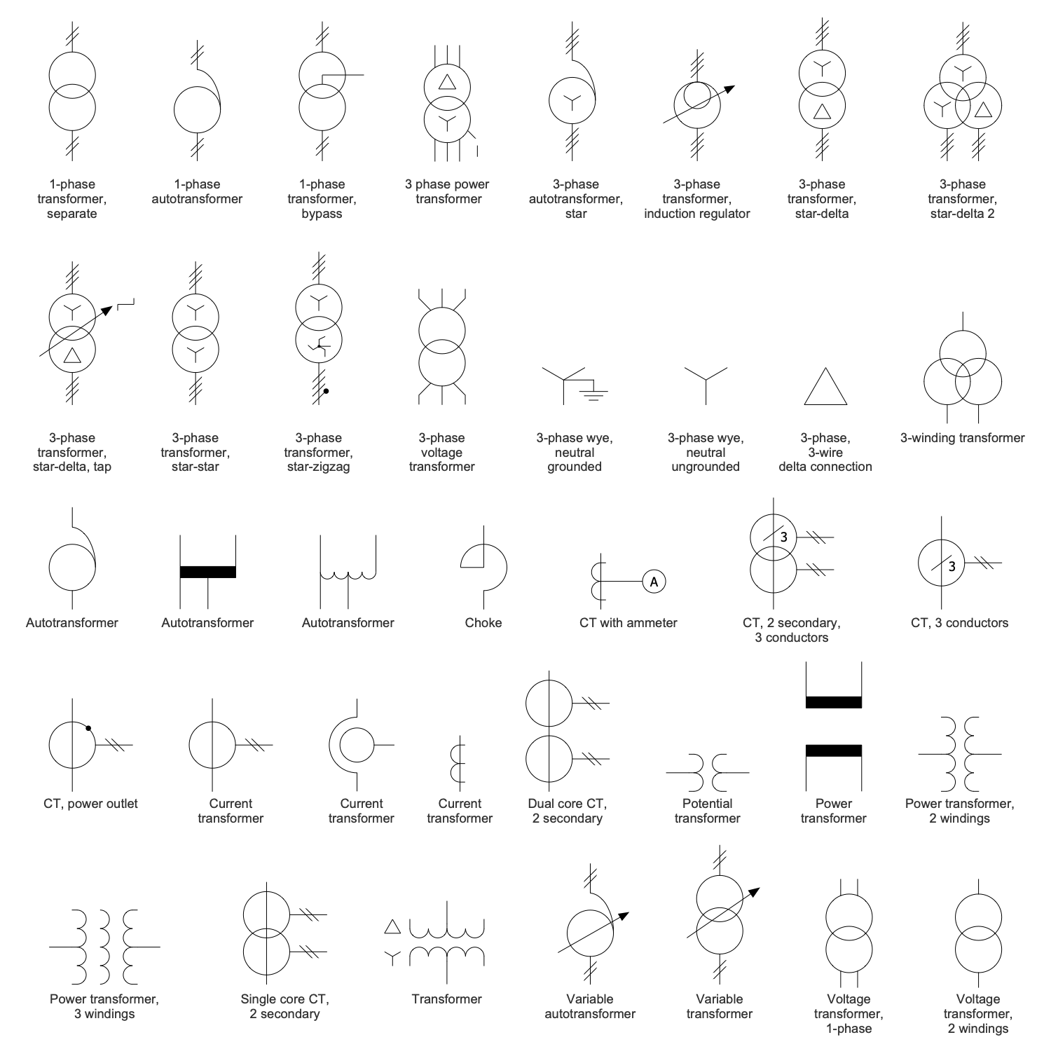
Design Elements — Transformers SLD
Related News:
Examples
There are a few samples that you see on this page which were created in the ConceptDraw DIAGRAM application by using the One-line Diagrams solution. Some of the solution's capabilities as well as the professional results which you can achieve are all demonstrated here on this page.
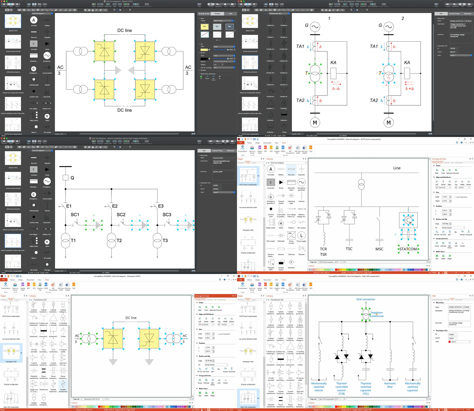
All source documents are vector graphic documents which are always available for modifying, reviewing and/or converting to many different formats, such as MS PowerPoint, PDF file, MS Visio, and many other graphic ones from the ConceptDraw Solution Park or ConceptDraw STORE. The One-line Diagrams solution is available to all ConceptDraw DIAGRAM users to get installed and used while working in the ConceptDraw DIAGRAM diagramming and drawing software.
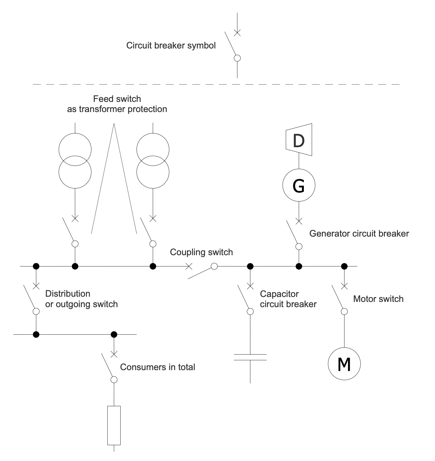
Example 1: One-Line Diagram — Application Examples of Circuit Breakers
This diagram was created in ConceptDraw DIAGRAM using a combination of libraries from the One-line Diagrams Solution. An experienced user spent 10 minutes creating this sample.
This One-line Diagram shows examples of circuit breaker applications. A circuit breaker is a device for automatic switching of contacts (mechanical or electronic) capable of switching on, conducting and disconnecting currents in a circuit. It is used to protect an electrical circuit from damage caused by short circuit or overcurrent. When a malfunction is detected, the circuit breaker interrupts the flow of current by opening the contacts. The device must later be rebooted manually or automatically to resume normal operation. Circuit breakers of different sizes and types are used to protect high voltage circuits and low-current circuits. As for the small mains and low voltage circuits, in common, circuit breakers detect the faults themselves. While the circuit breakers for large currents or high voltage circuits are supplied with protective relay pilot devices to track faults. Once the fault is eliminated, the contacts must be closed again and the circuit power restores.
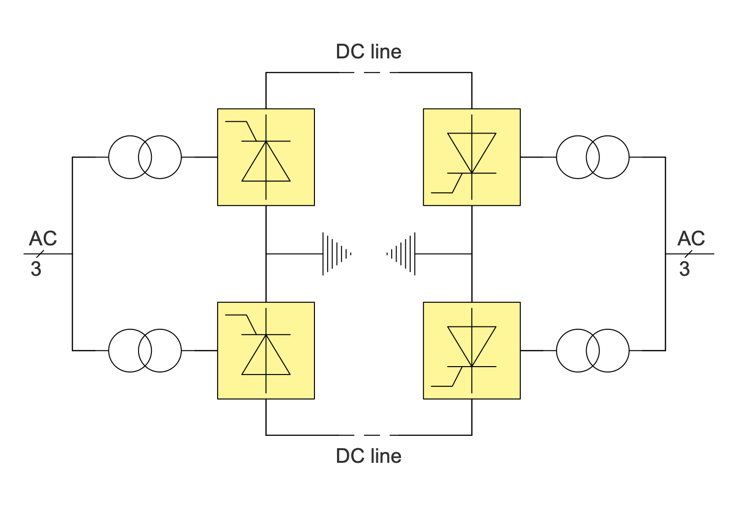
Example 2: One-Line Diagram — Bipolar HVDC
This diagram was created in ConceptDraw DIAGRAM using a combination of libraries from the One-line Diagrams Solution. An experienced user spent 10 minutes creating this sample.
This Single-line Diagram sample shows the bipolar HVDC transmission system. This type of transmission has a lot of advantages when compared to monopole transmission. This circuit uses a pair of insulated conductors. They have opposite polarity, high ground potential and can operate as two parallel monopoles. AC is a designation for alternating current and DC line for the direct-current transmission line correspondingly. Under normal load, a small amount of current flows in the ground, reduces ground losses and environmental impact. When a fault occurs on one of the lines of the bipolar system, it continues to operate, but with reduced power. Approximately half of the nominal power is transmitted over an undamaged line in monopolar mode using ground as the return conductor. To reduce losses, intermediate switching stations can be installed. This is undoubtedly the main advantage of bipolar HVDC. Each electrical symbol was taken off the shelf from the One-line Diagrams Solution libraries.
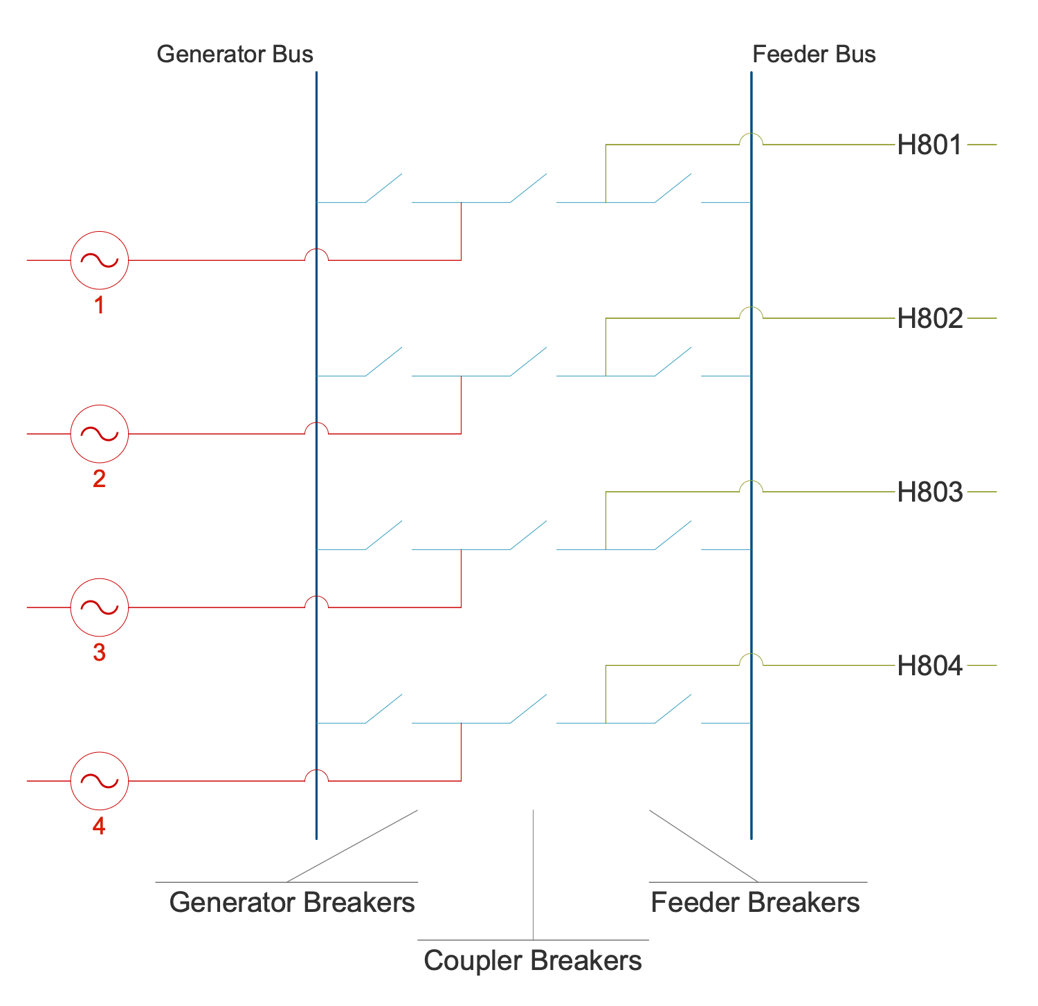
Example 3: Breaker and a Half Switchyard Design Concept
This diagram was created in ConceptDraw DIAGRAM using a combination of libraries from the One-line Diagrams Solution. An experienced user spent 10 minutes creating this sample.
This sample of One-line Diagram shows the breaker-and-a-half design concept used in switchyards. This configuration ensures that the failure of some circuit breaker does not interrupt power to other circuits. The One-line Diagram is obligatory to be constructed during planning a substation layout. Typically, it shows the arrangement of switching and protection equipment (switches, circuit breakers, transformers), incoming supply lines, outgoing feeders, transmission lines. In a common, incoming lines have a disconnect switch used to provide isolation or a circuit breaker used as a protective device. Both these devices can operate locally from a substation or remotely from a supervisory control center. The generator breaker, coupler breaker, and feeder breaker are installed. A circuit breaker can switch loads on and off, cut off a line when power flows in the wrong direction, and automatically interrupt fault currents detected by transformers. It is useful when the de-energizing of some parts is required for repair or maintenance of the system. The fault point is isolated without disrupting the rest part of the system. In turn, line entrance surge arrestors are used to protect substation equipment.
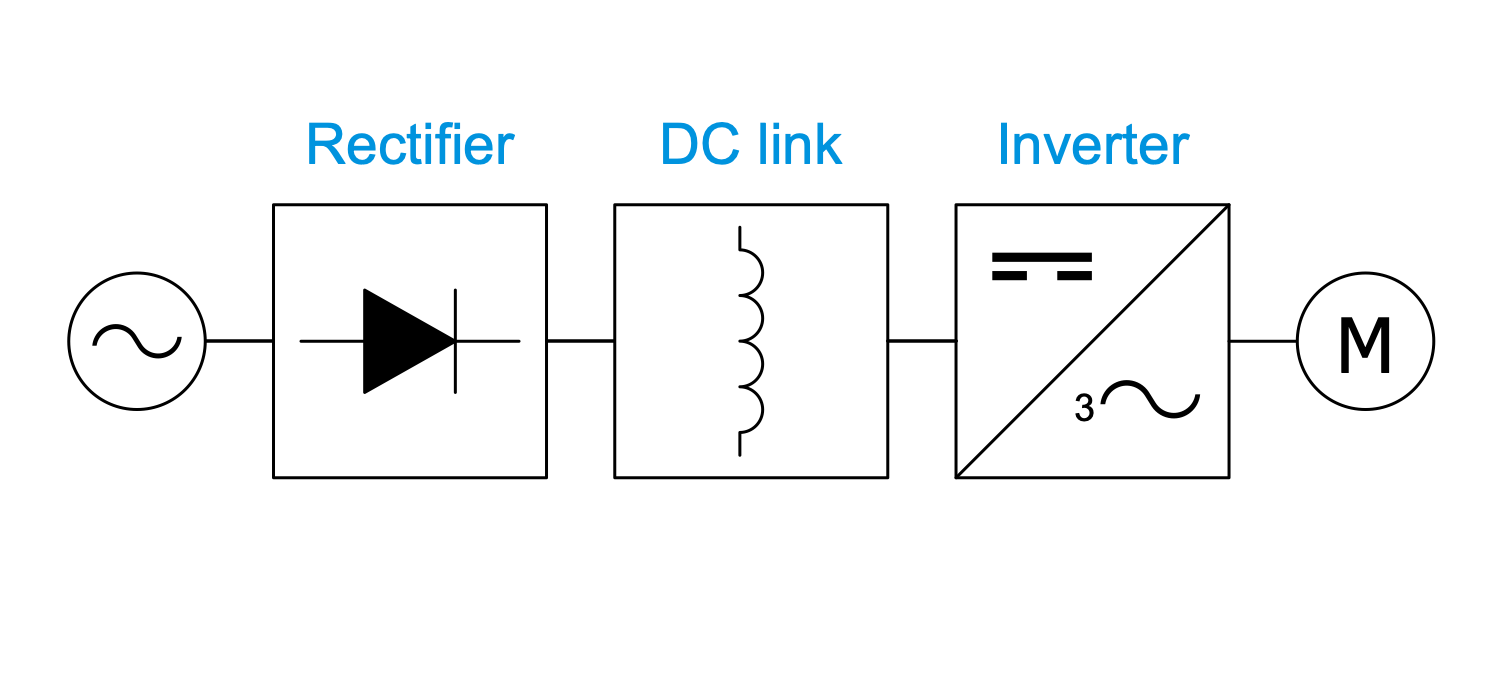
Example 4: One-Line Diagram — Current Source Inverter
This diagram was created in ConceptDraw DIAGRAM using a combination of libraries from the One-line Diagrams Solution. An experienced user spent 10 minutes creating this sample.
This One-line Diagram sample shows a topology of the current-source inverter (CSI) drive. It is also known as a current fed inverter because of its feeding with a constant current. CSI functions in closed-loop and isn't applied for multi-motor drives. CSI drive includes a rectifier, DC link, and inverter. The input current and load current are constant in CSI. The rectifier converts alternating current (AC) to direct current (DC), flowing in only one direction, and the intermediate circuit transfers this direct voltage to the inverter. In turn, the inverter converts DC voltage to AC, transmits current and frequency to the motor, adjusts the torque of the motor and operating speed. The CSI output is adjustable three-phase or single-phase AC current. CSI fed drive is reliable and even more than VSI drive, however, it has a lower speed range and slower dynamic response. For the reason of high harmonics in CSI drive, the use of filters on the input and output sides is required.
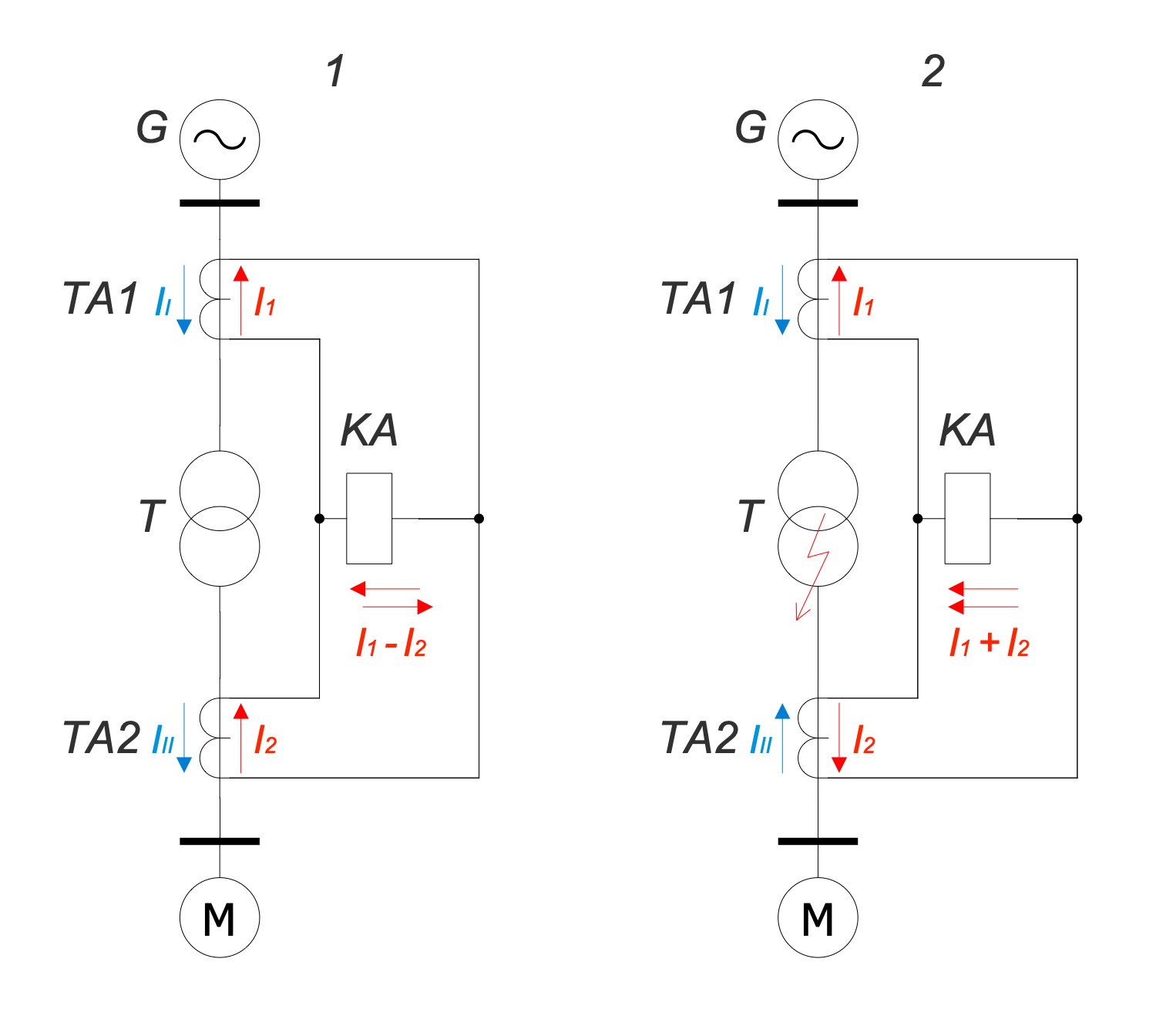
Example 5: One-Line Diagram — Differential Protection
This diagram was created in ConceptDraw DIAGRAM using a combination of libraries from the One-line Diagrams Solution. An experienced user spent 10 minutes creating this sample.
This sample of the One-line Diagram shows differential protection of the power transformer. Differential protection is one of the types of relay protection for transformers, autotransformers, generators, generator blocks, motors, overhead power lines, and busbars. It is characterized by absolute selectivity and high speed. The operating principle is based on the comparison of phase currents flowing through the sections between the protected line section. Two modes are displayed in a diagram — normal (1) and short circuit (2). The circuits include current transformers (TA1 and TA2) and current relay (KA). The transformers are used to measure the current strength at the ends of the protected area. They are connected to the current relay (KA) so that the current difference from these transformers falls on the relay winding. In normal mode, the values of the current strength are subtracted from each other (I1-I2) and the current relay winding circuit equals zero in an ideal case. In a short circuit the current relay winding receives the sum of the currents (I1+I2), this causes the close of contacts by relay and disconnection of a damaged section.
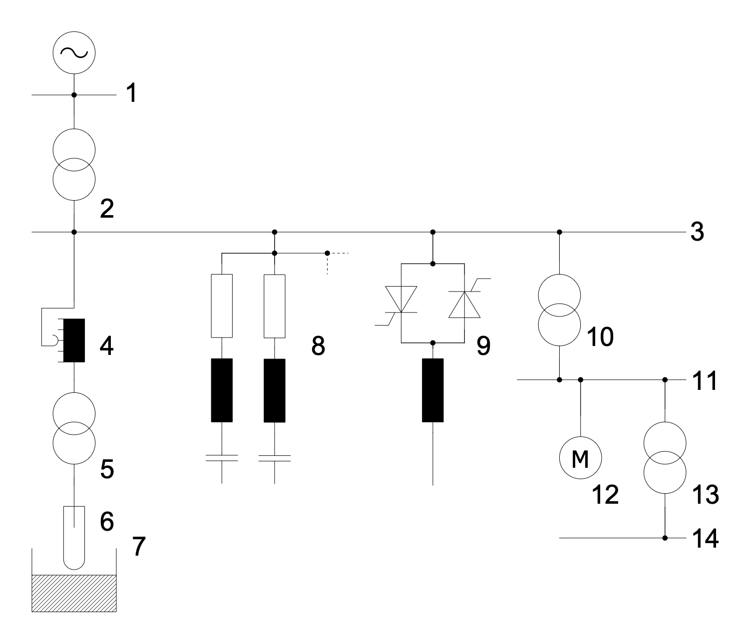
Example 6: One-Line Diagram — Electric Arc Furnace Plant Network
This diagram was created in ConceptDraw DIAGRAM using a combination of libraries from the One-line Diagrams Solution. An experienced user spent 10 minutes creating this sample.
This sample of one-line drawing shows an electrical on-site power grid in an electric arc furnace on a steel plant. An electric arc furnace (EAF) is a furnace using an electric arc to heat the materials. An electric arc affects the charged materials and the current from the furnace terminals passes through it. In this sample, the charged material is steel. High voltage main supply equals 110 kV, while the medium voltage auxilary grid of the steel plant is 34,5 kV and medium voltage grid for large loads is 6 kV. The on-site power grid includes the variable furnace reactor with on-load tap changer or no-load tap changer, electrodes, arc furnace, harmonic filter, power factor correction, large drive, and low voltage grids for small loads. It also includes different types of transformers: main power transformer, EAF transformer and step-down power transformers. Nowadays, the 60 MVA transformers are used on steel plants and their productivity is 80 tonnes of liquid steel in approximately 50 minutes.
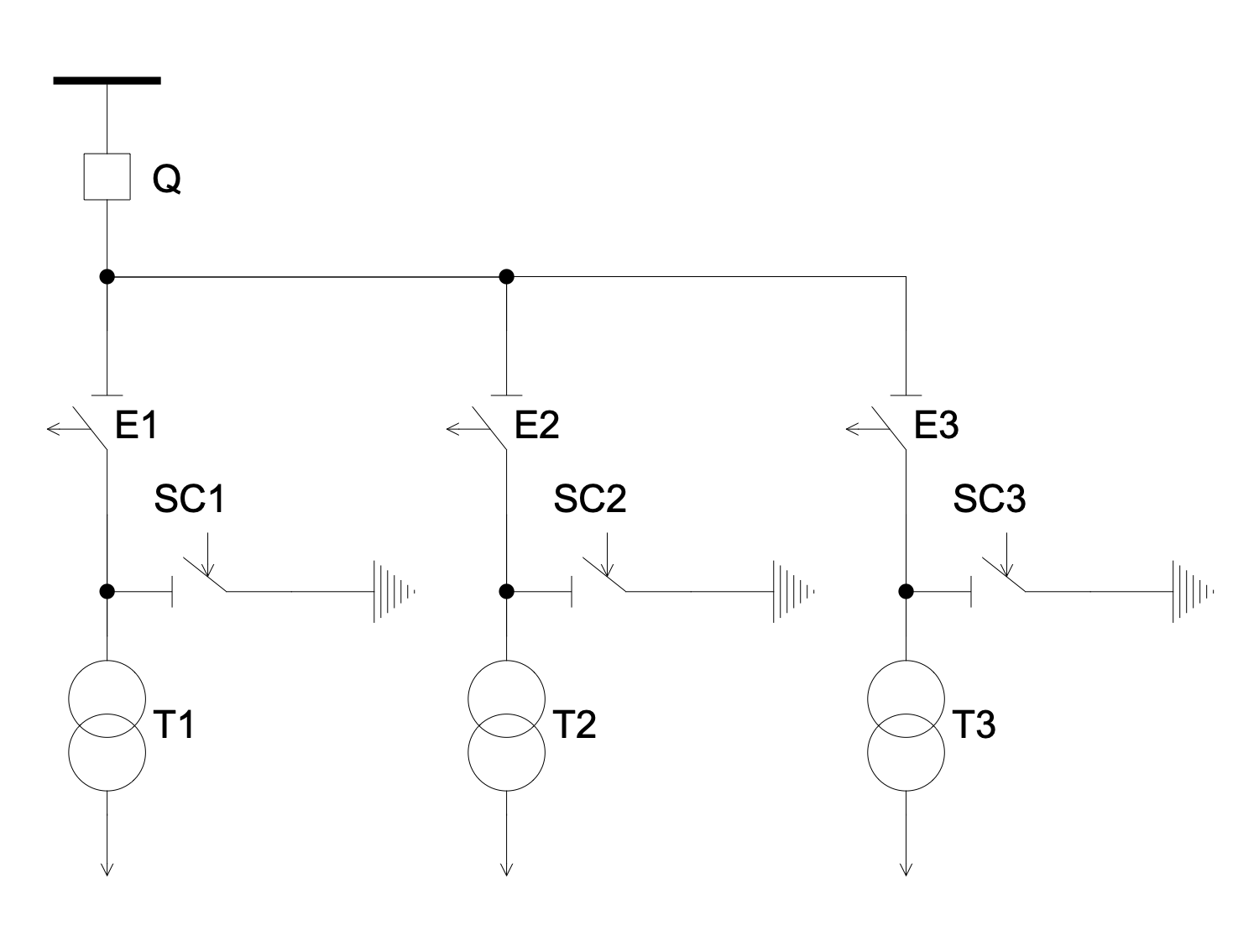
Example 7: Electric Substation without High Voltage Switchgear
This diagram was created in ConceptDraw DIAGRAM using a combination of libraries from the One-line Diagrams Solution. An experienced user spent 10 minutes creating this sample.
This electrical diagram shows an electrical substation without switches on the side. This substation includes three transformers (T1, T2, T3), three disconnectors (E1, E2, E3), three short circuit breakers (SC1, SC2, SC3) and a power line main switch (Q). In the event of an emergency on the line of one of the transformers, the protection installed on it supplies voltage to the switching coil of the corresponding short-circuit breaker. The short-circuit breaker, in turn, closes its contacts and causes an artificial ground fault. The main transmission line protection reacts to this short circuit and shuts down the entire substation using the main transmission line breaker. While the substation is off, the corresponding disconnector of the damaged transformer will close and disconnect it from the circuit, thereby disconnecting the damaged section. After a certain time, the main switch will turn on again and the substation will be able to work.
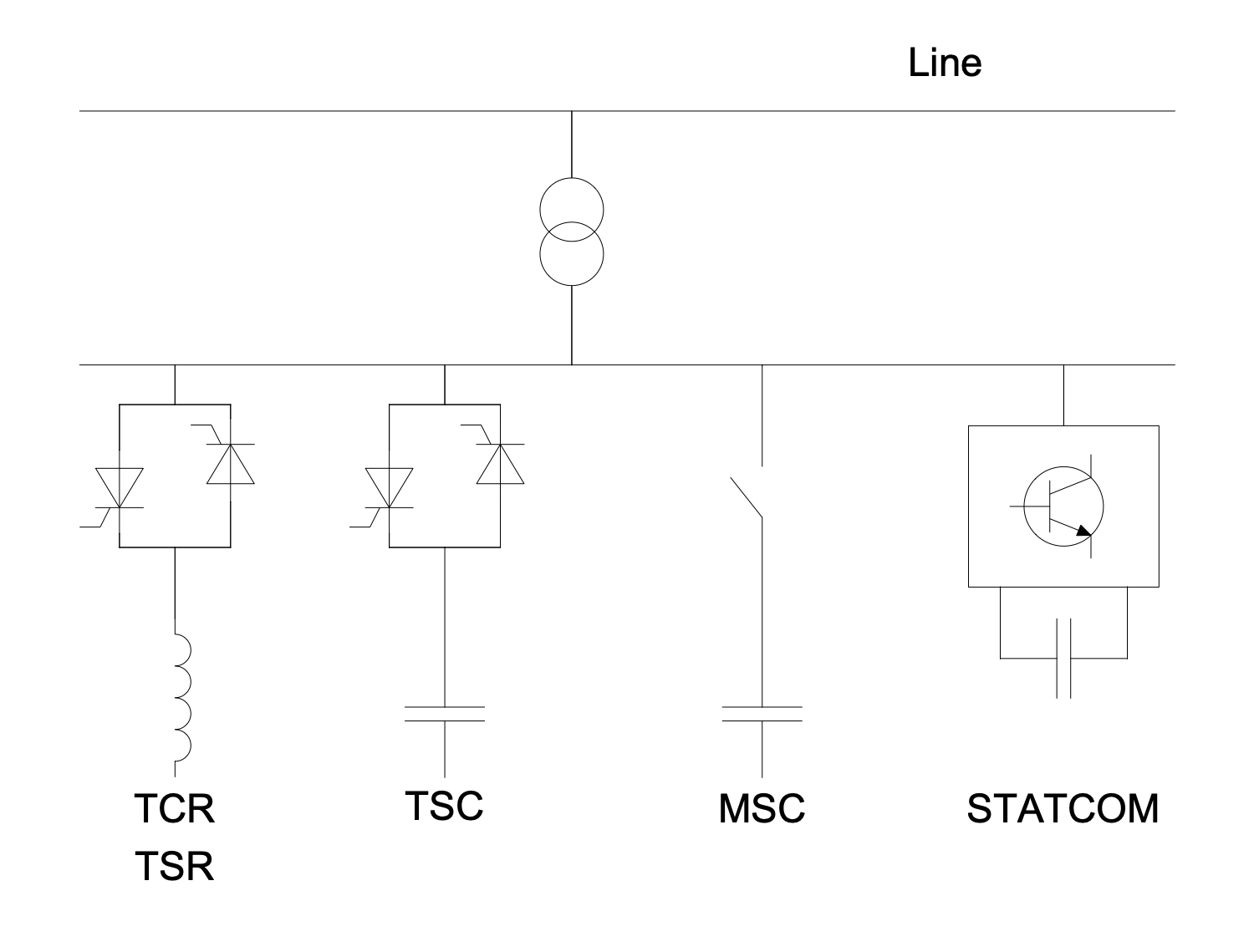
Example 8: One-Line Diagram — FACTS Shunt Compensation
This diagram was created in ConceptDraw DIAGRAM using a combination of libraries from the One-line Diagrams Solution. An experienced user spent 10 minutes creating this sample.
This sample shows examples of flexible alternating current transmission system (FACTS) for shunt compensation. FACTS enhances controllability and increases the power transfer capability of the network. It is a system including static equipment that uses an alternating current to transmit electrical energy. The shunt compensation supposes connection of the power system in shunt with the FACTS and operates as a controllable current source. Thyristor-controlled reactor (TCR), Thyristor-switched reactor (TSR), Thyristor-switched capacitor (TSC), Mechanically-switched capacitor (MSC), and Static synchronous compensator (STATCOM) are the examples. TCR is connected in series with a bidirectional phase-controlled thyristor valve, equivalent reactance changes continuously. TSR is similar to TCR and differs only by zero- or full- conduction of thyristor, equivalent reactance changes in a stepwise manner. Capacitor and bidirectional thyristor valve are connected in series with zero- or full- conduction in TSC, equivalent reactance is similar to TSR one. Capacitor in MSC is switched by circuit-breaker and compensates steady state reactive power.
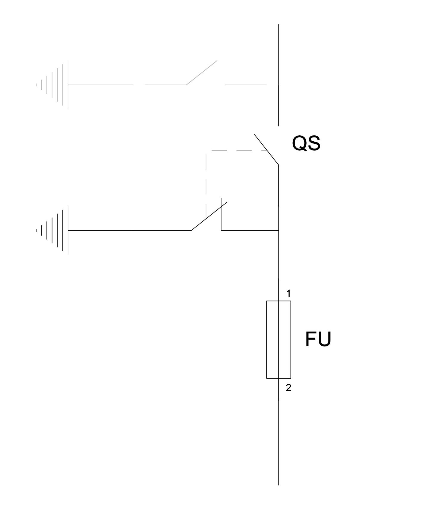
Example 9: One-Line Diagram — Grounding Knifes
This diagram was created in ConceptDraw DIAGRAM using a combination of libraries from the One-line Diagrams Solution. An experienced user spent 10 minutes creating this sample.
This sample shows a schematic of protection against the accidental return of voltage. It shows how to turn off the power in a distribution substation. According to the safety rules at the distribution substation, the grounding knifes must be obligatory launched into the ground before starting work. Two hot wires are used in USA and three in Europe. The diagram shows how to completely de-energize them for service or maintenance. The de-energizing is realized by means of disconnector, disconnect switch or isolator switch. This device opens the circuit and is operated manually or automatically. Together with the grounding switch, the grounding of the insulated part is also carried out. The disconnector is not a conventional circuit control method; it is just a protective decoupling method and does not contain an arc extinguishing mechanism. They only turn on when the current has been previously interrupted by some control device. Due to the presence of a label for blocking, accidental operation is excluded.
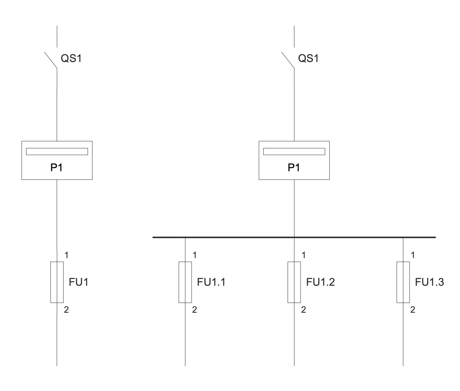
Example 10: One-Line Diagram — Low Power Electricity Meter
This diagram was created in ConceptDraw DIAGRAM using a combination of libraries from the One-line Diagrams Solution. An experienced user spent 10 minutes creating this sample.
This diagram shows an example of installing low-power (<80A) electricity meters. An electricity meter is a device used to measure the total amount of electricity consumed over a period of time. Induction single- and three-phase meters are used to account for active AC electricity. The movable part rotates during the consumption of electricity, and the counting mechanism takes into account its amount. The electricity meters are mounted in all electrified buildings and premises including residential buildings, commercial properties, offices, etc. The values of the electricity meters are informative for both consumers and power supply and distribution companies. They are used to create billings on payment for consumed electricity in each billing period. In addition, they allow monitoring the amount of electricity consumption by a certain property. The common billing unit for electricity meters is the kilowatt hour (kWh). Daily electricity demand and peak consumption data taken from electricity meters can also be useful for utilities.
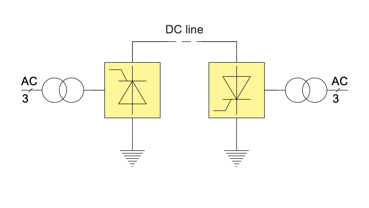
Example 11: One-Line Diagram — Monopolar HVDC
This diagram was created in ConceptDraw DIAGRAM using a combination of libraries from the One-line Diagrams Solution. An experienced user spent 10 minutes creating this sample.
This engineering diagram sample shows a monopolar high-voltage, direct current (HVDC) electric power transmission system with a ground return. In common, HVDC electric power transmission system uses direct current (DC) to transmit electrical power. It can also provide power transmission between non-synchronized AC transmission systems or grid systems operating at different frequencies. Sometimes monopolar systems are further used as a part of bipolar systems. In a monopolar system, the electrode line permanently carries the same current as the high-voltage conductor. One terminal of the rectifier is at a high voltage relative to the ground and is connected to a transmission line. The second terminal is connected to the ground and current flows between two electrodes. For the monopolar configuration with ground return, the ground current flow is unidirectional. The use of ground return is preferable for long-distance transmission. However, the installation of a metallic return conductor between two ends of the monopolar transmission line may be required.
Example 12: One-Line Diagram — Ring Bar Configuration
This diagram was created in ConceptDraw DIAGRAM using a combination of libraries from the One-line Diagrams Solution. An experienced user spent 10 minutes creating this sample.
This one-line diagram sample shows an electrical ring bus bar configuration. This configuration is used for electric power distribution inside switchgear, panel boards, busway enclosures. In addition, it allows low voltage equipment to be connected to batteries and high voltage equipment to switchgear. Ring bus systems are usually not isolated and have many advantages. Two lines are included. The starting and end points of the bus bar are connected together with the help of a ring. The circuit of the ring bus bar system has two parallel paths. A failure on one of them does not completely interrupt the operation of the circuit, because the other line is used as a backup path. Maintenance of one of the circuits is also possible without a complete interruption of the power supply, the necessary part simply gets isolated until the end of the work The disadvantages of ring bus systems include the difficulty of adding a new circuit line.

Example 13: One-Line Diagram — Static VAR Compensator
This diagram was created in ConceptDraw DIAGRAM using a combination of libraries from the One-line Diagrams Solution. An experienced user spent 10 minutes creating this sample.
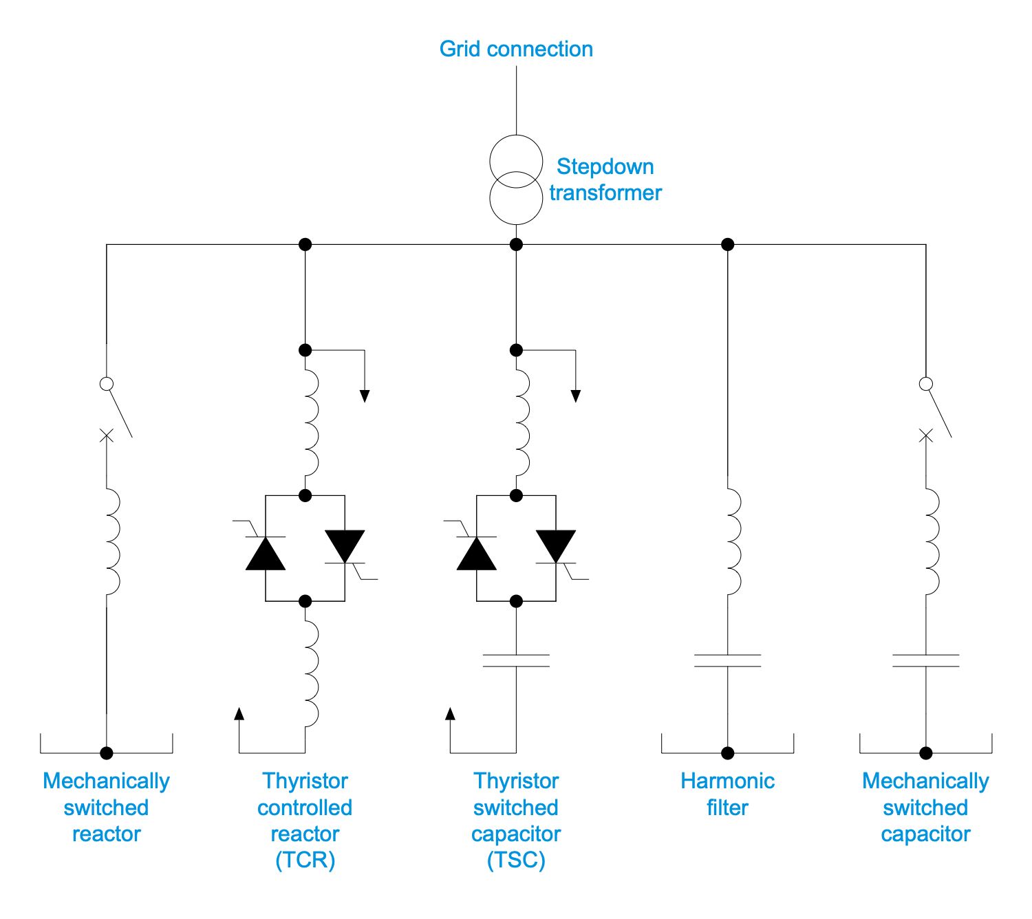
This sample shows a typical transmission static VAR сompensator (SVC). It has no significant moving parts except the internal switchgear. The SVC provides high speed reactive power in high voltage transmission networks, voltage regulation and system stabilization. A distinctive feature of static VAR сompensators is their ability to support the voltage changes in the system, their response to them is almost instant. SVC includes a set of electrical devices including thyristor controlled reactor (TCR), thyristor switched capacitor (TSC), harmonic filter, mechanically switched capacitor, mechanically switched reactor, grid connection, and stepdown transformer. The included capacitors or reactors are switched by thyristors providing smooth control and flexibility. The reactor ensures continuously variable VAR injection or absorption to the electrical network. In turn, the capacitor performs a coarse voltage adjustment.. Typically, thyristors are electronically controlled. They generate heat and are cooled by deionized water.
Example 14: One-Line Diagram — Voltage Source Inverter Topology
This diagram was created in ConceptDraw DIAGRAM using a combination of libraries from the One-line Diagrams Solution. An experienced user spent 10 minutes creating this sample.
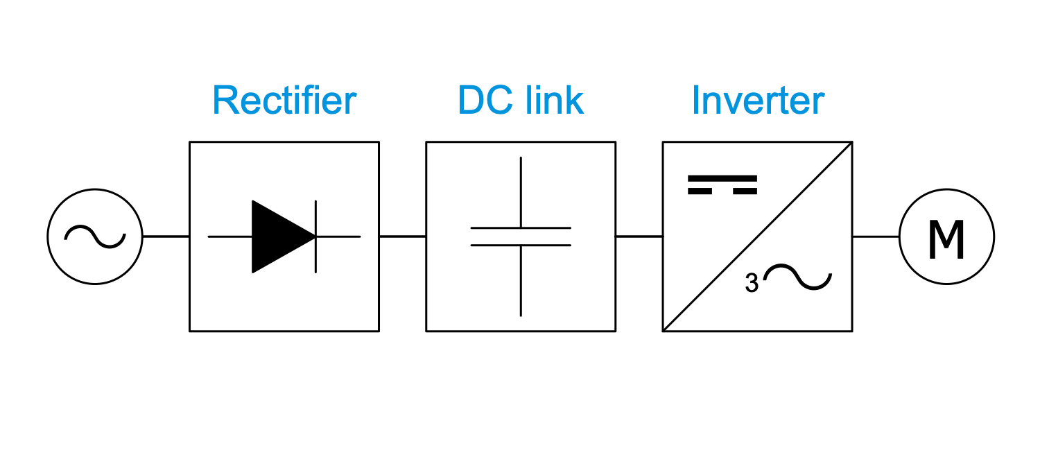
This example shows a voltage source inverter (VSI) drive topology. Most drives are VSI type with PWM output voltage. VSI is a conventional power inverter used to convert DC voltage to AC voltage with variable value and frequency. The output voltage at VSI is constant. A voltage source inverter (VSI) topology is one of the typical topologies. The VSI drive consists of a rectifier, a DC link and a converter. A diode rectifier only allows energy to flow in one direction from the power source to the drive, while an inverter allows energy to flow in different directions. An output DC voltage is applied to the input of the inverter. The maximum output voltage is limited because the voltage at the input to the inverter is limited by the peak line-to-line voltage of the power supply, and then it is further reduced by voltage drops across the inverter. VSI topology provides high efficiency and minimal installation time. It is very reliable, providing fast dynamic response and the ability to run motors without derating.
Inside
What I Need to Get Started
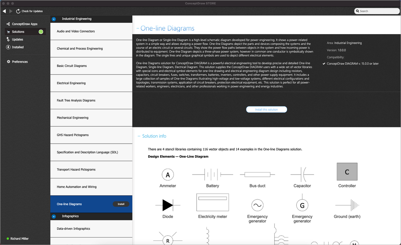
Both ConceptDraw DIAGRAM diagramming and drawing software and the One-line Diagrams solution can help creating the illustrations the technical documentation of an engineering projects you need. The One-line Diagrams solution can be found in the Industrial Engineering area of ConceptDraw STORE application that can be downloaded from this site. Make sure that both ConceptDraw DIAGRAM and ConceptDraw STORE applications are installed on your computer before you get started.
How to install
After ConceptDraw STORE and ConceptDraw DIAGRAM are downloaded and installed, you can install the One-line Diagrams solution from the ConceptDraw STORE.
Start Using
To make sure that you are doing it all right, use the pre-designed symbols from the stencil libraries from the solution to make your drawings look smart and professional. Also, the pre-made examples from this solution can be used as drafts so your own drawings can be based on them. Using the samples, you can always change their structures, colors and data.
