- Electric and Telecom Plans Free
- Fire and Emergency Plans Free
- Floor Plans Free
- Plant Layout Plans Free
- School and Training Plans Free
- Seating Plans Free
- Security and Access Plans Free
- Site Plans Free
- Sport Field Plans Free
- Business Process Diagrams Free
- Business Process Mapping Free
- Classic Business Process Modeling Free
- Cross-Functional Flowcharts Free
- Event-driven Process Chain Diagrams Free
- IDEF Business Process Diagrams Free
- Logistics Flow Charts Free
- Workflow Diagrams Free
- ConceptDraw Dashboard for Facebook Free
- Mind Map Exchange Free
- MindTweet Free
- Note Exchange Free
- Project Exchange Free
- Social Media Response Free
- Active Directory Diagrams Free
- AWS Architecture Diagrams Free
- Azure Architecture Free
- Cisco Network Diagrams Free
- Cisco Networking Free
- Cloud Computing Diagrams Free
- Computer Network Diagrams Free
- Google Cloud Platform Free
- Interactive Voice Response Diagrams Free
- Network Layout Floor Plans Free
- Network Security Diagrams Free
- Rack Diagrams Free
- Telecommunication Network Diagrams Free
- Vehicular Networking Free
- Wireless Networks Free
- Comparison Dashboard Free
- Composition Dashboard Free
- Correlation Dashboard Free
- Frequency Distribution Dashboard Free
- Meter Dashboard Free
- Spatial Dashboard Free
- Status Dashboard Free
- Time Series Dashboard Free
- Basic Circle-Spoke Diagrams Free
- Basic Circular Arrows Diagrams Free
- Basic Venn Diagrams Free
- Block Diagrams Free
- Concept Maps Free
- Family Tree Free
- Flowcharts Free
- Basic Area Charts Free
- Basic Bar Graphs Free
- Basic Divided Bar Diagrams Free
- Basic Histograms Free
- Basic Line Graphs Free
- Basic Picture Graphs Free
- Basic Pie Charts Free
- Basic Scatter Diagrams Free
- Aerospace and Transport Free
- Artwork Free
- Audio, Video, Media Free
- Business and Finance Free
- Computers and Communications Free
- Holiday Free
- Manufacturing and Maintenance Free
- Nature Free
- People Free
- Presentation Clipart Free
- Safety and Security Free
- Analog Electronics Free
- Audio and Video Connectors Free
- Basic Circuit Diagrams Free
- Chemical and Process Engineering Free
- Digital Electronics Free
- Electrical Engineering Free
- Electron Tube Circuits Free
- Electronic Block Diagrams Free
- Fault Tree Analysis Diagrams Free
- GHS Hazard Pictograms Free
- Home Automation and Wiring Free
- Mechanical Engineering Free
- One-line Diagrams Free
- Power Сircuits Free
- Specification and Description Language (SDL) Free
- Telecom and AV Circuits Free
- Transport Hazard Pictograms Free
- Data-driven Infographics Free
- Pictorial Infographics Free
- Spatial Infographics Free
- Typography Infographics Free
- Calendars Free
- Decision Making Free
- Enterprise Architecture Diagrams Free
- Fishbone Diagrams Free
- Organizational Charts Free
- Plan-Do-Check-Act (PDCA) Free
- Seven Management and Planning Tools Free
- SWOT and TOWS Matrix Diagrams Free
- Timeline Diagrams Free
- Australia Map Free
- Continent Maps Free
- Directional Maps Free
- Germany Map Free
- Metro Map Free
- UK Map Free
- USA Maps Free
- Customer Journey Mapping Free
- Marketing Diagrams Free
- Matrices Free
- Pyramid Diagrams Free
- Sales Dashboard Free
- Sales Flowcharts Free
- Target and Circular Diagrams Free
- Cash Flow Reports Free
- Current Activities Reports Free
- Custom Excel Report Free
- Knowledge Reports Free
- MINDMAP Reports Free
- Overview Reports Free
- PM Agile Free
- PM Dashboards Free
- PM Docs Free
- PM Easy Free
- PM Meetings Free
- PM Planning Free
- PM Presentations Free
- PM Response Free
- Resource Usage Reports Free
- Visual Reports Free
- House of Quality Free
- Quality Mind Map Free
- Total Quality Management TQM Diagrams Free
- Value Stream Mapping Free
- Astronomy Free
- Biology Free
- Chemistry Free
- Language Learning Free
- Mathematics Free
- Physics Free
- Piano Sheet Music Free
- Android User Interface Free
- Class Hierarchy Tree Free
- Data Flow Diagrams (DFD) Free
- DOM Tree Free
- Entity-Relationship Diagram (ERD) Free
- EXPRESS-G data Modeling Diagram Free
- IDEF0 Diagrams Free
- iPhone User Interface Free
- Jackson Structured Programming (JSP) Diagrams Free
- macOS User Interface Free
- Object-Role Modeling (ORM) Diagrams Free
- Rapid UML Free
- SYSML Free
- Website Wireframe Free
- Windows 10 User Interface Free
Network Layout Floor Plans
The network visualization is widely developed in a modern world and is applied by the network and system administrators, and other computer and network-related specialists. The general plan of the premises, electrical plan, plumbing plan, plan of arrangement the furniture, and in many cases network layout plan are the obligatory set of documents when planning a new construction, as well as the major refurbishment of existing buildings. The network layout, the choice of cable type and networking equipment, as well as developing the network layout plan are especially important when we are talking about the premises with complex layout, multifloor buildings and multiroom spaces. From the correctness of the made choice and thought-out network layout determines the speed of data transmission and the network security.
Network Layout Floor Plans solution extends ConceptDraw DIAGRAM software functionality with powerful tools for quick and efficient documentation the network equipment and displaying its location on the professionally designed Network Layout Floor Plans. Never before creation of this type of plans was not so easy, convenient and fast as with predesigned templates, samples, examples and comprehensive set of vector design elements included to the Network Layout Floor Plans solution. Besides, now you don't need to be professional designer and have special knowledge and skills to create professionally-looking, clear and accurate Network Layout Floor Plans, Network Communication Plans, Network Topologies Plans and Network Topology Maps, which will be a good support for the future correct cabling and installation of network equipment.
-
Install this solution Free -
What I need to get started -
Solution Requirements - This solution requires the following products to be installed:
ConceptDraw DIAGRAM v18 - This solution requires the following products to be installed:
-
Compatibility - Sonoma (14), Sonoma (15)
MS Windows 10, 11 - Sonoma (14), Sonoma (15)
-
Support for this Solution -
Helpdesk
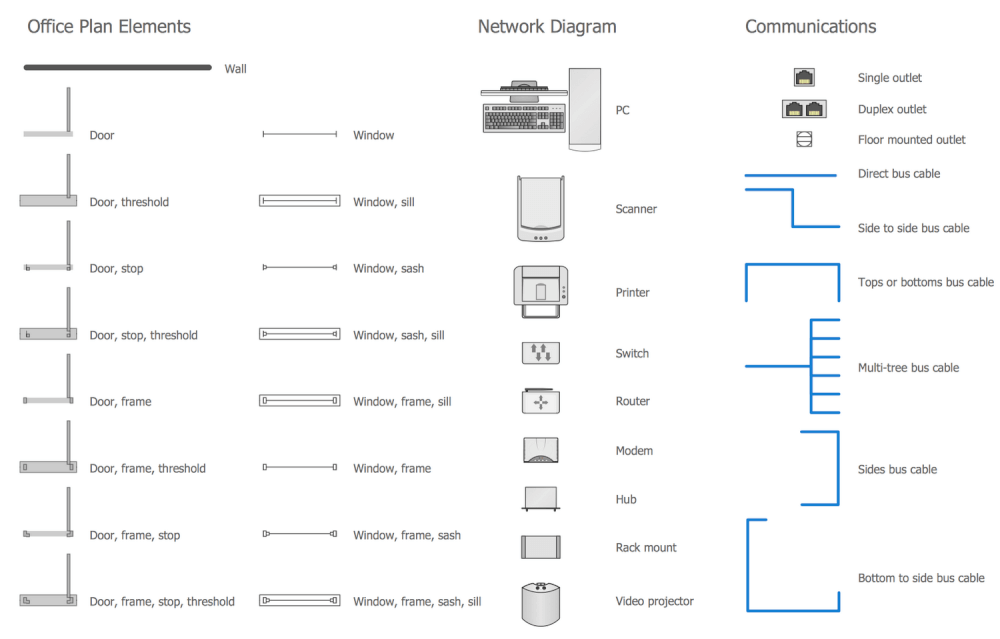
There is 1 library containing 35 home networking vector shapes in the Network Layout Floor Plans solution.
Design Elements — Network Communication Plan
Related News:
Five Solutions for ConceptDraw DIAGRAM, They Can Be Found in the Computer and Networks Area
Examples
There are a few samples that you see on this page which were created in the ConceptDraw DIAGRAM application by using the Network Layout Floor Plans solution. Some of the solution's capabilities as well as the professional results which you can achieve are all demonstrated here on this page.
All source documents are vector graphic documents which are always available for modifying, reviewing and/or converting to many different formats, such as MS PowerPoint, PDF file, MS Visio, and many other graphic ones from the ConceptDraw Solution Park or ConceptDraw STORE. The Network Layout Floor Plans solution is available to all ConceptDraw DIAGRAM users to get installed and used while working in the ConceptDraw DIAGRAM diagramming and drawing software.
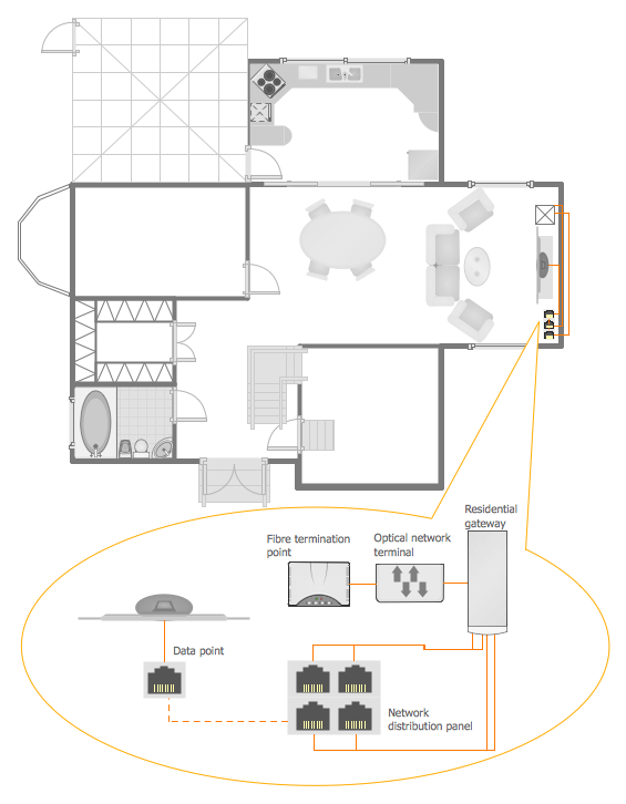
Example 1: Home Network Plan
This diagram was created in ConceptDraw DIAGRAM using the Network Communication Plan Library from the Network Layout Floor Plans Solution, and the Kitchen and Dining Room and Bathroom libraries from the Floor Plans Solution. An experienced user spent 20 minutes creating this sample.
The Home Area Network (HAN) is a kind of local area network (LAN) that lets facilitate communication and interaction among the electronic and digital devices mounted within a small area of a home. At this, the Home Area Network can be wired or wireless, typically it consists of a broadband Internet connection, which is shared between multiple users through a wired or wireless modem. This sample shows a Home Network Plan to assist when building internet communications within a home. You may notice that it is a complete home plan with location of furniture. The detailed scheme depicting location of digital devices, the arrangement of gateways, outlets and termination points is allocated separately at the callout. Creating a plan is one of the base steps when implementing a home network. Now, the network visualization is quick and simple when using the Network Layout Floor Plans solution for ConceptDraw DIAGRAM.
Example 2: Network Communication Plan
This diagram was created in ConceptDraw DIAGRAM using the Network Communication Plan Library from the Network Layout Floor Plans Solution. An experienced user spent 15 minutes creating this sample.
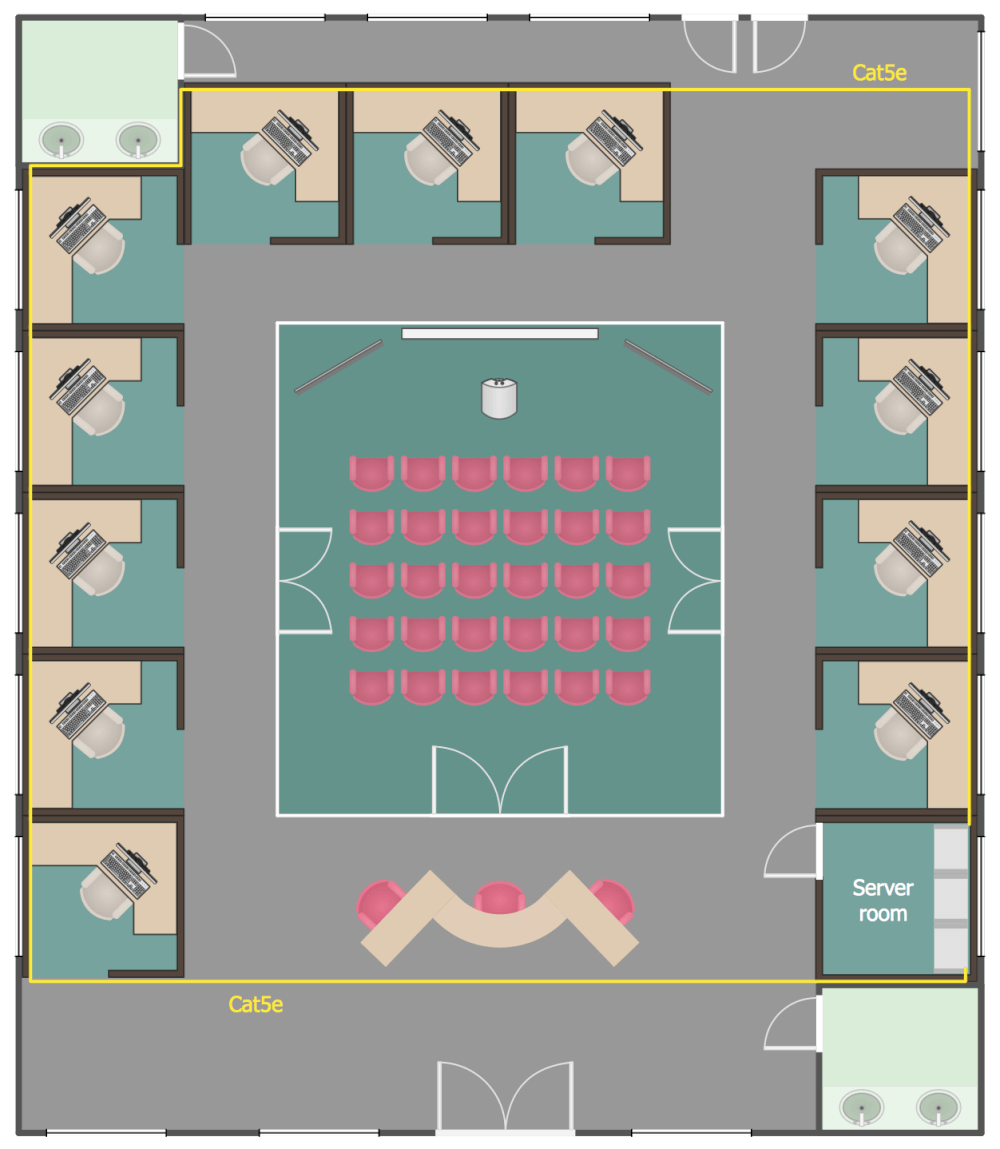
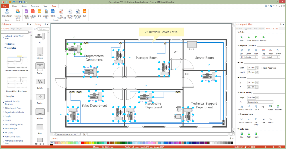
Do you need to draw a network layout floor plan, network topologies diagram, network topology mapper, or a network communication plan similar to this sample? Usually, the process of planning and designing of network communication plans and other listened types of plans is sufficiently complex. But now, this process is maximally facilitated, you can use a predesigned sample or template from the selection provided through ConceptDraw Store, the predesigned vector objects of network and communication elements and devices offered in quantity at the libraries. The physical topology depicts the placement of different network components, devices and cables, the interconnections between the network nodes and cabling. On this Network Communication Plan is used a cable Cat5e, which is one of the types of cables used to transmit the signals and comprised of four twisted pairs. Usually Cat5e cable is unshielded and is used in structured cabling for computer networks such as Ethernet.
Example 3: Ethernet Cable Layout
This diagram was created in ConceptDraw DIAGRAM using the Network Communication Plan Library from the Network Layout Floor Plans Solution. An experienced user spent 15 minutes creating this sample.
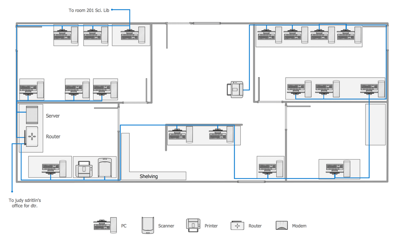
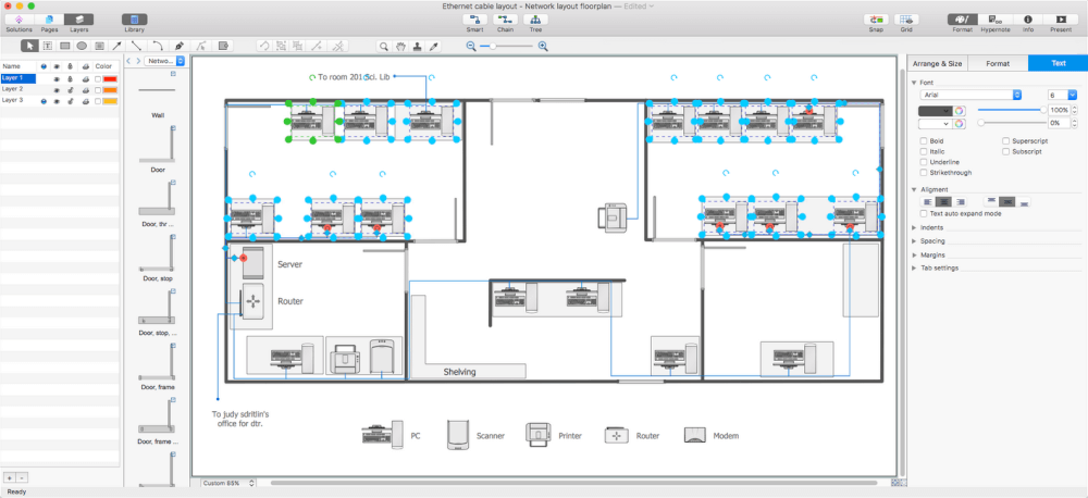
This network layout floor plan example visualizes an Ethernet Cable Layout diagram that is a "UGA Technical Network Liaison Handbook" based on the data from the website of the University of Georgia. Ethernet is a common family of computer networking technologies of organization the local area network (LAN), the packet transfer of data for computer network and larger networks. The Ethernet standards determine the wiring and electrical signals at the physical level. Ethernet uses the concept of shared broadcast, each computer sends the data to this broadcast and indicates to whom they are addressed. The data can reach all computers on the network, but are handled only one to whom they are intended, another computers ignore the data of others. Currently the Ethernet standard almost always involves connection through a switch, in this case the data reach only to the addressee, which greatly increases the speed of work and network security.
Example 4: Network Floor Plan Layout
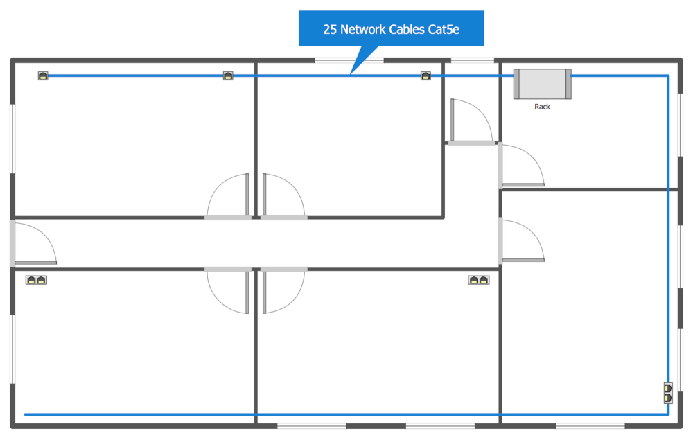
This diagram was created in ConceptDraw DIAGRAM using the Network Communication Plan Library from the Network Layout Floor Plans Solution. An experienced user spent 20 minutes creating this sample.
The Ethernet physical layer, which is a component of Ethernet family of computer network standards, was developed over a long time period and includes several physical media interfaces and magnitudes of speed. The speed range depends from the type of cable (this can be bulky coaxial cable, the twisted pair or optical fiber cable) and takes the values from 1 Mbit/s to 100 Gbit/s. At this, the network protocol stack software works almost similarly on all physical layers. This sample represents in details a Network Floor Plan Layout and shows a plan of an Ethernet computer network that will be constructed using a category 5 cable (Cat 5e). Cat 5e is a twisted pair cable for carrying signals. It is convenient to use callouts to convey the additional information for a viewer of this plan and it is a good idea to visually indicate the cable type on a callout.
Example 5: Restaurant Network Layout Floor Plan
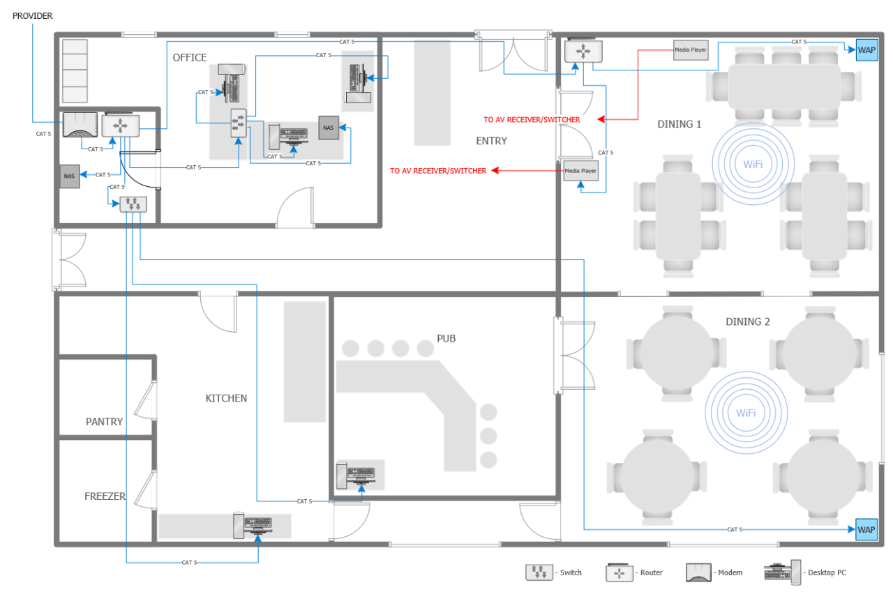
This diagram was created in ConceptDraw DIAGRAM using the Network Communication Plan Library from the Network Layout Floor Plans Solution, and the Cafe and Restaurant Library from Cafe and Restaurant Plans. An experienced user spent 25 minutes creating this sample.
This computer network layout floor plan was drawn on the base of the picture from the Media Institute blog of the Madison Media Institute. It depicts the plan of restaurant premises on the Restaurant Network Layout Floor Plan, with arrangement of all furniture and restaurant equipment. The legend assists in description the types of special equipment, the graphic symbols of which are used on a given diagram. The bright colors are applied to depict the cable laying and important details. ConceptDraw DIAGRAM diagramming and vector drawing software gives you all tools you need for drawing effective plans when designing a restaurant or cafe. First, you can draw a detailed restaurant floor plan using the tools of Cafe and Restaurant Floor Plan solution from the Building Plans area of ConceptDraw Solution Park, then work out the furniture arrangement, and finally add a network layout plan to illustrate the Internet access available in your establishmen
Example 6: Ethernet LAN Layout Floor Plan
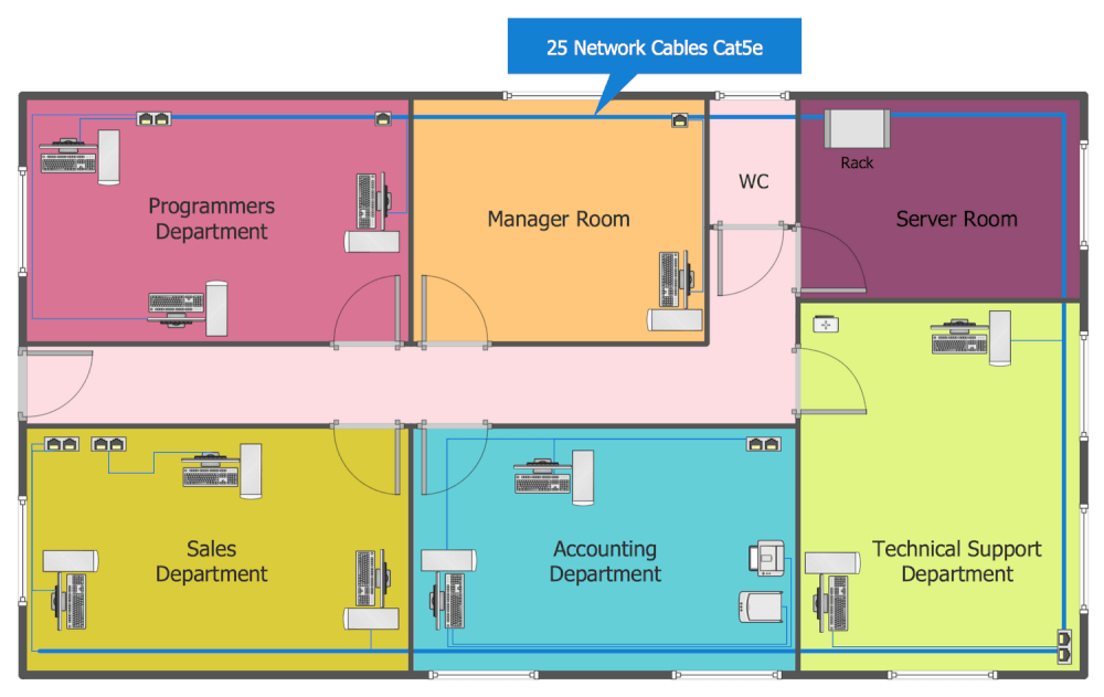
This diagram was created in ConceptDraw DIAGRAM using the Network Communication Plan Library from the Network Layout Floor Plans Solution. An experienced user spent 20 minutes creating this sample.
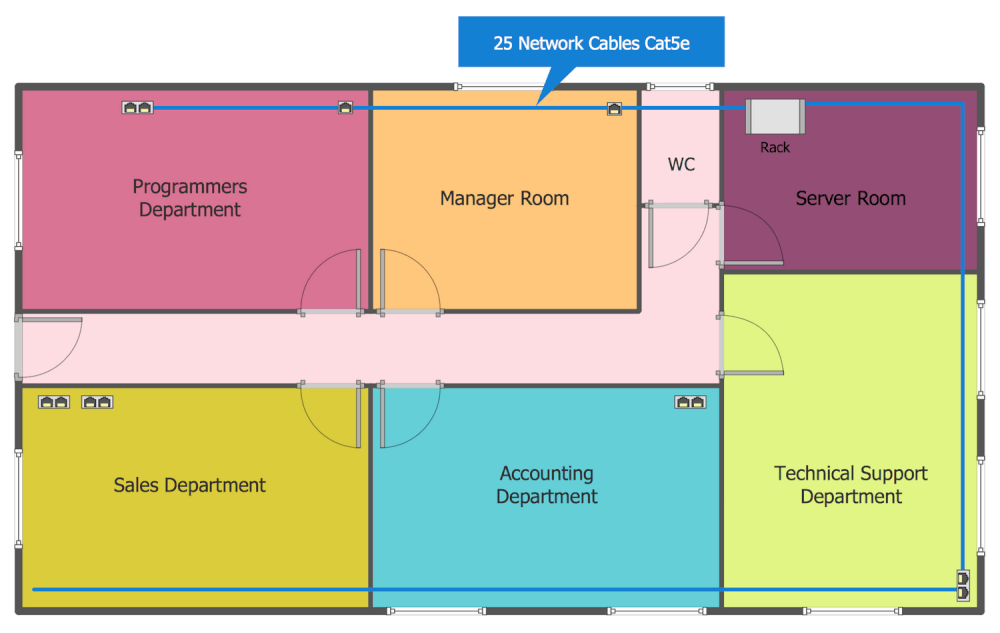
A Local Area Network (LAN) is a network that covers some small area like a room, office, bank, business center, or any other premises or building. Today, the most commonly used LAN is Ethernet, which lets to transmit the data over a LAN with a speed of a gigabit per second, uses the bus or star topology and is based on the technology of multiple access with a carrier sense and collision detection (CSMA/CD). The Ethernet is a standard that uses the principle of random access to the shared environment, which can be a coaxial cable, twisted pair, fiber optic cable, and radio waves. This sample is the Ethernet LAN Layout on the typical office floor plan. There are represented all office departments on this diagram, the arrangement of computer equipment, network devices and cabling at the office premises. Each department's room is colored with its own color for more visuality.
Example 7: Ground Floor Office LAN Plan
This diagram was created in ConceptDraw DIAGRAM using the Network Communication Plan Library from the Network Layout Floor Plans Solution. An experienced user spent 20 minutes creating this sample.
The convenience of location the workplaces and quick access to the high-speed Internet are incredibly important in conditions of the modern world, today’s business and office standards. This sample designed with help of ready-to-use vector elements from the ConceptDraw Solution Park libraries, demonstrates detailed plan of the LAN within the office’s ground floor. However, today are very popular large office buildings and office centers, which include several floors and each of them also requires a well thought-out location of premises, workplaces and cabling. ConceptDraw DIAGRAM software is a perfect in all these questions, use it to project and design professionally the office buildings and schematics of location the cables within them not depending the type of chosen Internet cable to be mounted. Don't afraid to make your diagrams colorful and bright, such diagrams always attract attention and will be popular and appropriate, add also the legend, informative callouts and multicolored clipart.
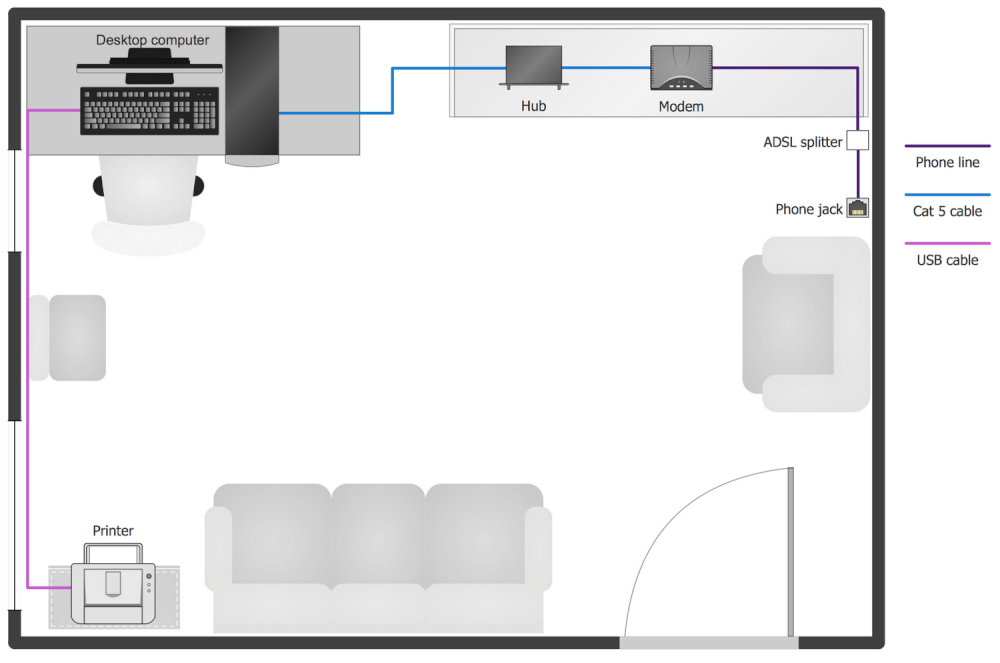
Example 8: Home Study Network Layout
This diagram was created in ConceptDraw DIAGRAM using the Network Communication Plan Library from the Network Layout Floor Plans Solution. An experienced user spent 20 minutes creating this sample.
The successes of each pupil and student largely dependent on the space and properly organized workplace as at the educational institution and at home. How to organize the working space so that the pupil and student can to focus attention, to improve their performance and to achieve the excellent results in study, as well as have the opportunity to relax in the pauses? It is necessary to pay great attention to the correct location of furniture, good lighting, design and color style of the room. Start with making a detailed plan and then proceed with accomplishment the workplace of a pupil or student. At the same time in modern conditions, when the Internet is an integral part of each person's life, it is equally important to make the plan of location of the network equipment. This sample represents the Home Study Network Layout with useful legend describing the types of used cables.
Example 9: Network Equipment Layout and Cabling
This diagram was created in ConceptDraw DIAGRAM using the Network Communication Plan Library from the Network Layout Floor Plans Solution. An experienced user spent 20 minutes creating this sample.
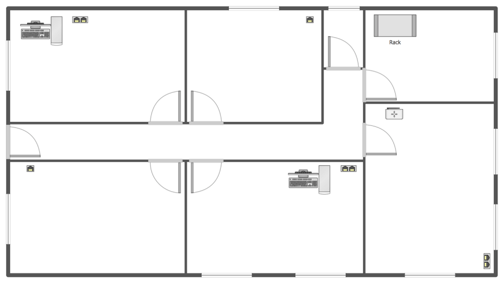
The development of the mounting plan of the network connections and location of the network equipment in buildings of organizations, as well as the development of plans of the laying the cable lines between the buildings require a lot of special knowledge, attention from the specialists and experts at this field, and it is also desirable the availability of a special software for professional designing the network diagrams, plans and schematics. An important role for the plan composition plays the length and number of floors at the building, location of premises and the placement of network equipment inside the building, all these parameters determine the kinds of network devices and the type of cable needed to be used for installation. This sample diagram demonstrating the network equipment layout and cabling was designed using the tools of Network Layout Floor Plans solution for the best network visualization and network mapper software ConceptDraw DIAGRAM
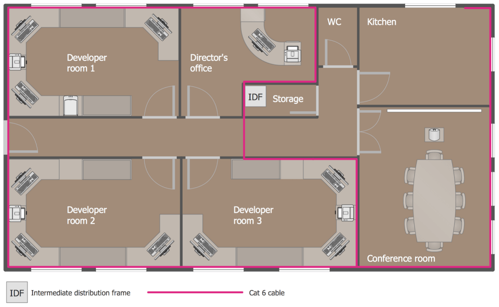
Example 10: Office Network Floor Plan
This diagram was created in ConceptDraw DIAGRAM using the Network Communication Plan Library from the Network Layout Floor Plans Solution. An experienced user spent 20 minutes creating this sample.
The work of a modern office often requires the high-quality access to the global network Internet, as well as connecting computers in a Local Area Network (LAN), which offers wide opportunities, such as lets to organize the printing from all workplaces to a network printer, to connect and to configure the Internet channel, to organize the Internet access from all computers of the LAN and the reliable LAN protect from external intrusions, to install and to configure the network services (WEB server, mail server, file server, FTP, proxy, etc.), etc. This sample depicts the Network Floor Plan for the office of software development company. The qualitative Internet access is a necessity at this case. You can observe that this office includes the following premises: director’s office, three developer rooms, conference room and restroom. The cabling of Cat 6 is mounted over all office and is designated on a diagram by red line.
Example 11: Office Network Layout
This diagram was created in ConceptDraw DIAGRAM using the Network Communication Plan Library from the Network Layout Floor Plans Solution. An experienced user spent 20 minutes creating this sample.
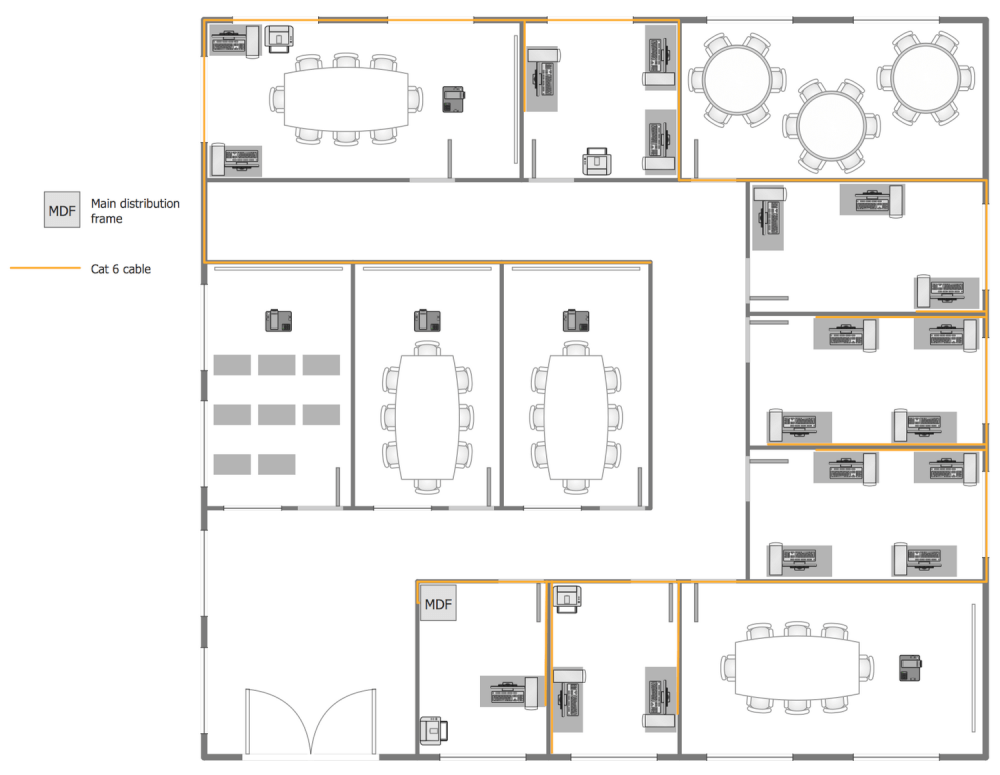
How to build a network within the office premise? It is necessary to start from designing the plan or sketch of the projected network. The main task when developing such project is to choose the best path for mounting the cables from the workplaces and for the placement the switch. A huge role plays the type of premise, its layout, material and thickness of walls, so in each particular case it is necessary to make an individual plan. Furthermore, the beforehand thoughtful plan helps to avoid the errors at the stage of purchase the network equipment and materials, as well as further laying of cables and installation of network equipment. This sample shows detailed network layout floor plan at the office building with many rooms. If your office building is a multifloor, the ConceptDraw DIAGRAM software lets design the similar plans for all floors of your building in a few minutes.
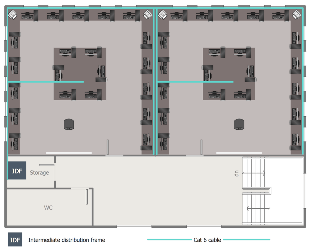
Example 12: Second Floor Network Layout Plan
This diagram was created in ConceptDraw DIAGRAM using the Network Communication Plan Library from the Network Layout Floor Plans Solution. An experienced user spent 20 minutes creating this sample.
This sample illustrates the Network Layout Plan on the second floor at the office building with use of Cat 6 cable, which is a standardized twisted pair cable for Ethernet and also other network physical layers, and is compatible with the Category 3 and Category 5/5e cable standards. You can see two identical working premises with large quantity of workplaces on this floor. The quantity of such premises maybe even more in several times, but it is not a problem for ConceptDraw DIAGRAM software, which assists in drawing the plans of any complexity for the buildings of any area and quantity of floors. The placement of cabling, servers and other network equipment with respect to the firewalls and computers greatly affects the network productivity and security, that is why it is needed to be taken seriously and thoroughly the questions of choosing the cable type, of creation the network layout plans and implementing them.
Inside
What I Need to Get Started
Both ConceptDraw DIAGRAM diagramming and drawing software and the Network Layout Floor Plans solution can help creating the network layout floor plans you need. The Network Layout Floor Plans solution can be found in the Computer and Networks area of ConceptDraw STORE application that can be downloaded from this site. Make sure that both ConceptDraw DIAGRAM and ConceptDraw STORE applications are installed on your computer before you get started.
How to install
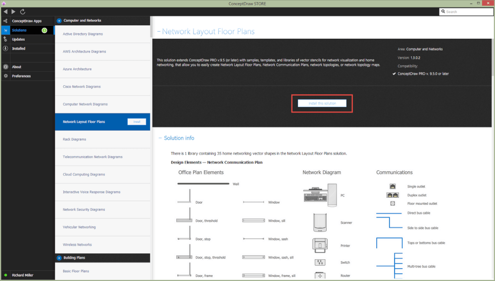
After ConceptDraw STORE and ConceptDraw DIAGRAM are downloaded and installed, you can install the Network Layout Floor Plans solution from the ConceptDraw STORE.
Start using
To make sure that you are doing it all right, use the pre-designed symbols from the stencil libraries from the solution to make your drawings look smart and professional. Also, the pre-made examples from this solution can be used as drafts so your own drawings can be based on them. Using the samples, you can always change their structures, colors and data.
