Products
Solutions
Samples
Contact Us
Buy
Helpdesk
✕
Sign In
Sign In
My ConceptDraw
Profile
Cart 
Activate
My Activated Licenses
Upgrade Information
Download Product
Open Support Ticket
Sign Out
This site uses cookies. By continuing to browse the ConceptDraw site you are agreeing to our Use of Site Cookies.
Helpdesk  >  ConceptDraw DIAGRAM  >    Business-specific Drawings

How to Create a Network Layout Floor Plan

The Network Layout Diagram is used to show the location of your company network equipment. Making a network floor plan involves many different elements that can be managed using ConceptDraw DIAGRAM The ability to design network floor plans is delivered by the Network Layout Floor Plans solution.

Combining the elements from network typologies creates a layered picture of the network architecture, which can basically be defined as the design of a communications network - a floor plan for its physical components, and a clearly defined set of principles and procedures. Logical and physical topology diagrams combined with floor plan are ideal for depicting office network. To create a practical computer network floor plan, the network administrator must adhere to the specified requirements and limitations of the office or building in which the LAN will operate - things such as hardware availability, company budget, and customer needs must all be taken into account. To create a Physical Network Diagram, you should draw your office layout and your network equipment.
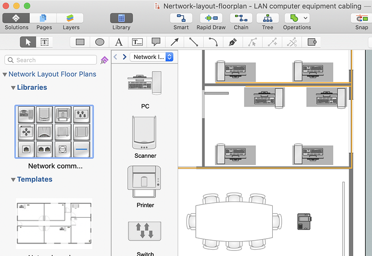
  1. Open a ConceptDraw DIAGRAM new document.
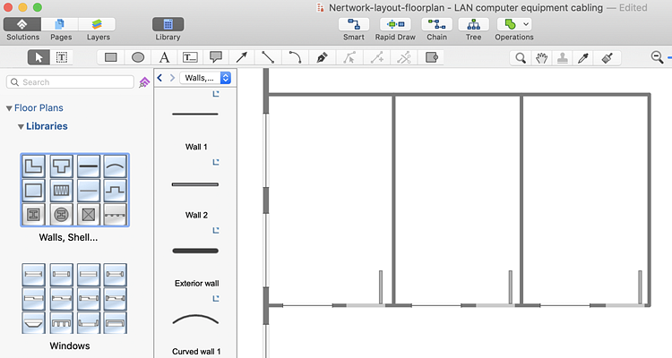
  2. Use libraries supplied with the Floor Plans solution to depict the layout of rooms and other floor plan details.
  3. design-network-floor-plan-layout
  4. Find the Network Layout Floor Plans solution's library.
  5. Add network objects to the drawing by dragging them from the libraries panel to the document page.
  6. network-floor-plan-layout
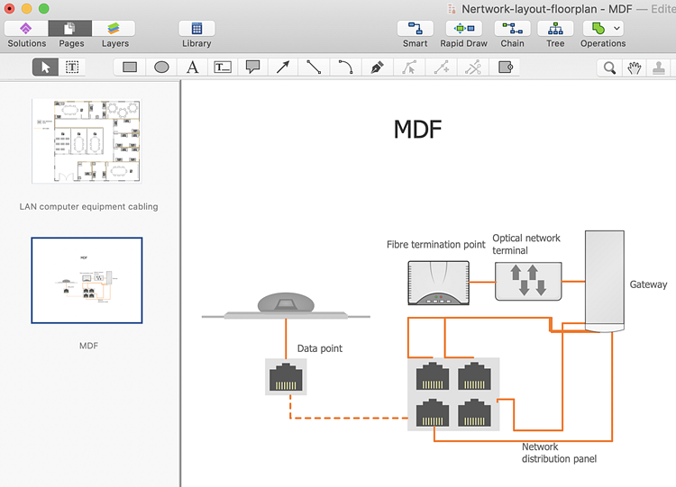
  7. Place a more detailed plan of important nodes of your network on separate pages.
  8. network-floor-plan
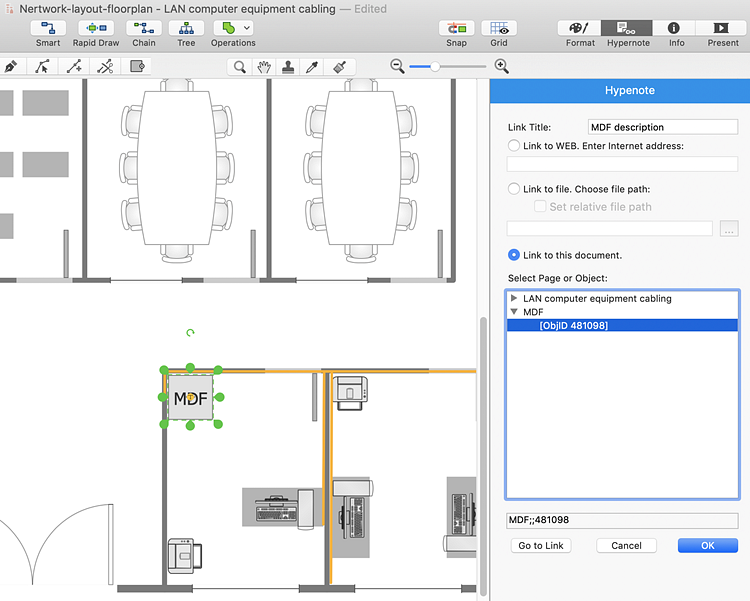
  9. You can link objects on different pages using the Hypernote panel.
  10. network-layout

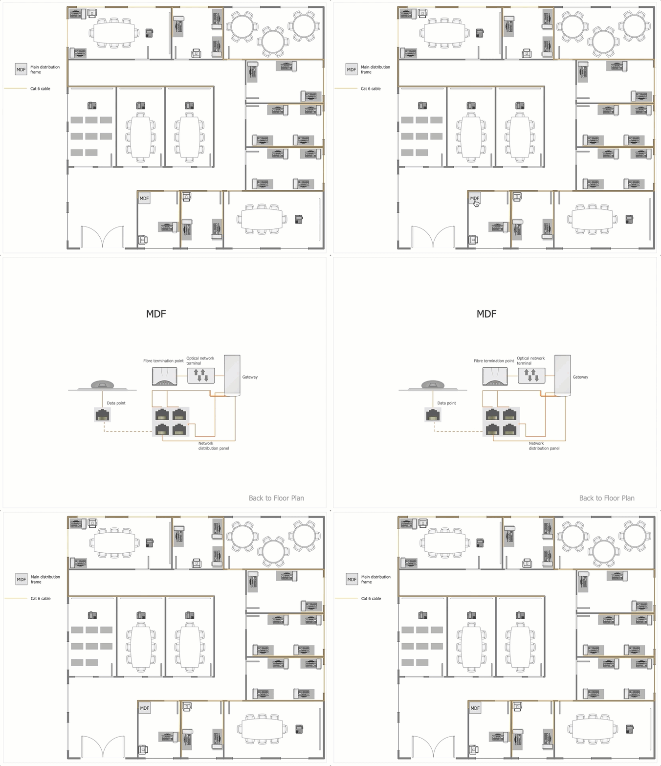
Result: This way you will be able to click a network equipment symbol on your network floorplan and drill down to its content.

How to Create a Network Layout Floor Plan

How it works:

  • Set of ready-to-use templates supplied with ConceptDraw DIAGRAM
  • Collection of professional samples supports each template
  • Professional drawing tools

Useful Solutions and Products:

Computer and Network
  • Microsoft Azure Architecture Diagrams
  • AWS Arcitecture Diagrams
  • Active Directory Diagrams
  • Wireless Nerwork Diagram
  • IVR Diagram
  • ISG Topology Diagram Cisco®

Diagrams area
  • Easily draw charts and diagrams.
  • Visualize business information
  • Block Diagrams
  • Bubble Diagrams
  • Circle-Spoke Diagrams
  • Circular Arrows Diagrams
  • Concept Maps
  • Flowcharts
  • Venn Diagrams

ConceptDraw DIAGRAM
  • Diagraming and Charts
  • Vector Illustrations
  • Maps
  • Floor plans
  • Engineering drawings
  • Business dashboards
  • Infographics
  • Presentation
  • Over 10 000 vector stencils
  • Export to vector graphics files
  • Export to Adobe Acrobat® PDF
  • Export to MS PowerPoint®
  • Export to MS Visio® VSDX, VDX

Products

  • ConceptDraw OFFICE v11
  • ConceptDraw DIAGRAM v18
  • ConceptDraw MINDMAP v16
  • ConceptDraw PROJECT v15
  • ConceptDraw STORE
  • ConceptDraw BOOKS

Solutions

  • Free
  • Premium

Samples

Support

  • Technical Support
  • Upgrade Request
  • Visio File Conversion
  • System Requirements
  • Helpdesk
  • Students & Educators
  • Enterprise
  • Customer Service

Solutions

  • Free
  • Premium

Samples

Video Room

  • Products
  • Solutions

Ready To Buy

  • Buy Online
  • Reseller Partners
  • Manage Your Account
  • Download Your Software
  • CS Odessa

    • About Us
    • Contact Us
    • CS Odessa Identity
    • News
  • CS Odessa
    Plan. Do. Communicate.

    About Us | Contact Us | Feedback | EULA | Privacy | TOU | TOS
    © 1993 — 2025 CS Odessa Corp.