- Electric and Telecom Plans Free
- Fire and Emergency Plans Free
- Floor Plans Free
- Plant Layout Plans Free
- School and Training Plans Free
- Seating Plans Free
- Security and Access Plans Free
- Site Plans Free
- Sport Field Plans Free
- Business Process Diagrams Free
- Business Process Mapping Free
- Classic Business Process Modeling Free
- Cross-Functional Flowcharts Free
- Event-driven Process Chain Diagrams Free
- IDEF Business Process Diagrams Free
- Logistics Flow Charts Free
- Workflow Diagrams Free
- ConceptDraw Dashboard for Facebook Free
- Mind Map Exchange Free
- MindTweet Free
- Note Exchange Free
- Project Exchange Free
- Social Media Response Free
- Active Directory Diagrams Free
- AWS Architecture Diagrams Free
- Azure Architecture Free
- Cisco Network Diagrams Free
- Cisco Networking Free
- Cloud Computing Diagrams Free
- Computer Network Diagrams Free
- Google Cloud Platform Free
- Interactive Voice Response Diagrams Free
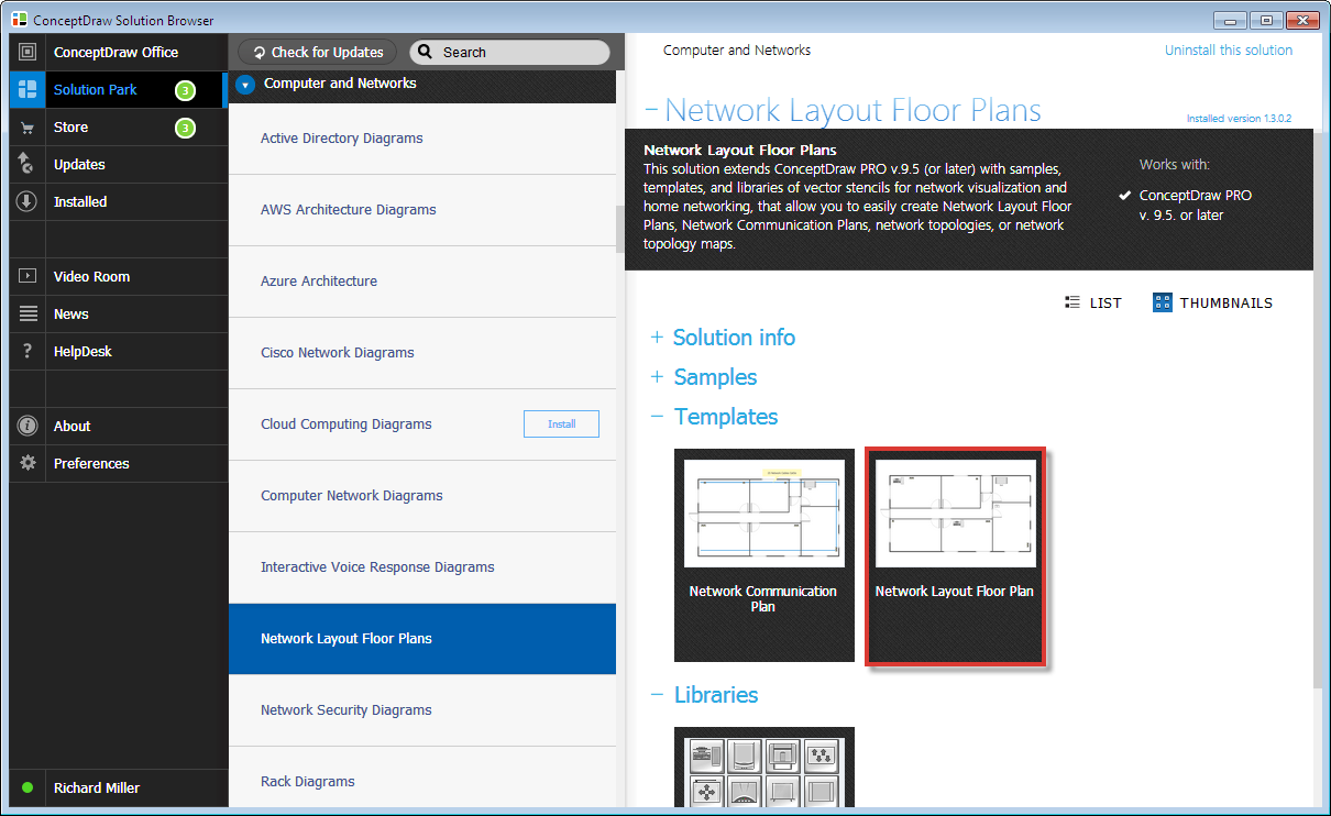
- Network Layout Floor Plans Free
- Network Security Diagrams Free
- Rack Diagrams Free
- Telecommunication Network Diagrams Free
- Vehicular Networking Free
- Wireless Networks Free
- Comparison Dashboard Free
- Composition Dashboard Free
- Correlation Dashboard Free
- Frequency Distribution Dashboard Free
- Meter Dashboard Free
- Spatial Dashboard Free
- Status Dashboard Free
- Time Series Dashboard Free
- Basic Circle-Spoke Diagrams Free
- Basic Circular Arrows Diagrams Free
- Basic Venn Diagrams Free
- Block Diagrams Free
- Concept Maps Free
- Family Tree Free
- Flowcharts Free
- Basic Area Charts Free
- Basic Bar Graphs Free
- Basic Divided Bar Diagrams Free
- Basic Histograms Free
- Basic Line Graphs Free
- Basic Picture Graphs Free
- Basic Pie Charts Free
- Basic Scatter Diagrams Free
- Aerospace and Transport Free
- Artwork Free
- Audio, Video, Media Free
- Business and Finance Free
- Computers and Communications Free
- Holiday Free
- Manufacturing and Maintenance Free
- Nature Free
- People Free
- Presentation Clipart Free
- Safety and Security Free
- Analog Electronics Free
- Audio and Video Connectors Free
- Basic Circuit Diagrams Free
- Chemical and Process Engineering Free
- Digital Electronics Free
- Electrical Engineering Free
- Electron Tube Circuits Free
- Electronic Block Diagrams Free
- Fault Tree Analysis Diagrams Free
- GHS Hazard Pictograms Free
- Home Automation and Wiring Free
- Mechanical Engineering Free
- One-line Diagrams Free
- Power Сircuits Free
- Specification and Description Language (SDL) Free
- Telecom and AV Circuits Free
- Transport Hazard Pictograms Free
- Data-driven Infographics Free
- Pictorial Infographics Free
- Spatial Infographics Free
- Typography Infographics Free
- Calendars Free
- Decision Making Free
- Enterprise Architecture Diagrams Free
- Fishbone Diagrams Free
- Organizational Charts Free
- Plan-Do-Check-Act (PDCA) Free
- Seven Management and Planning Tools Free
- SWOT and TOWS Matrix Diagrams Free
- Timeline Diagrams Free
- Australia Map Free
- Continent Maps Free
- Directional Maps Free
- Germany Map Free
- Metro Map Free
- UK Map Free
- USA Maps Free
- Customer Journey Mapping Free
- Marketing Diagrams Free
- Matrices Free
- Pyramid Diagrams Free
- Sales Dashboard Free
- Sales Flowcharts Free
- Target and Circular Diagrams Free
- Cash Flow Reports Free
- Current Activities Reports Free
- Custom Excel Report Free
- Knowledge Reports Free
- MINDMAP Reports Free
- Overview Reports Free
- PM Agile Free
- PM Dashboards Free
- PM Docs Free
- PM Easy Free
- PM Meetings Free
- PM Planning Free
- PM Presentations Free
- PM Response Free
- Resource Usage Reports Free
- Visual Reports Free
- House of Quality Free
- Quality Mind Map Free
- Total Quality Management TQM Diagrams Free
- Value Stream Mapping Free
- Astronomy Free
- Biology Free
- Chemistry Free
- Language Learning Free
- Mathematics Free
- Physics Free
- Piano Sheet Music Free
- Android User Interface Free
- Class Hierarchy Tree Free
- Data Flow Diagrams (DFD) Free
- DOM Tree Free
- Entity-Relationship Diagram (ERD) Free
- EXPRESS-G data Modeling Diagram Free
- IDEF0 Diagrams Free
- iPhone User Interface Free
- Jackson Structured Programming (JSP) Diagrams Free
- macOS User Interface Free
- Object-Role Modeling (ORM) Diagrams Free
- Rapid UML Free
- SYSML Free
- Website Wireframe Free
- Windows 10 User Interface Free
Computer Network Diagrams
Today it is impossible to imagine any human activity without the use of computers and computer networks, which provide abilities of fast communication and rapid exchange of information. A computer network is a combination of nodes (computers and network equipment), which are connected with communication channels and switching equipment in a common system to exchange the messages and to provide for all network users the access to common program, technical, informational and organizational resources of the network. A computer network consists at least of two computers, which interact with each other. Depending on the remoteness of computers and the scope, the networks are divided into the local and global. The local area network connects the group of computers and is typically deployed on a small limited area, within some organization, building or small group of buildings, office, home, university, school or any other premise. The global area networks cover large geographical areas from the hundreds to thousands kilometers, include large number of computers, and can also contain the local area networks, telecommunication networks and other devices. The global area networks are intended for unlimited number of subscribers, but offer the smaller speed than the local networks. Sometimes, it is allocated the intermediate class of networks, such as urban or regional networks located within specific cities, regions, etc.
The computers can be connected at the networks in various ways. The logical and physical ways of connecting computers, cables and other components of a network are called its topology. The physical topology specifies the geometric arrangement of network nodes, communication lines relatively to network nodes and physical connections of nodes, while the logical topology describes the flow of data between network nodes and data transmission methods. The network topology determines the main characteristics of the network and can be of several types. The basic topologies are Bus, Star, Ring, each of them has its advantages and disadvantages. The network topology in which all computers are connected to a central hub with a point-to-point connection, is named Star topology. If the computers are connected along a single cable, such topology is called Bus. When the connecting cable is closed in a ring, topology is called Ring. At this, the logical and physical network topologies will not necessarily be the same. Moreover, in real networks can be often found the complicated combinations joining the properties of several topologies.
Computer Network Diagrams solution extends ConceptDraw DIAGRAM software with samples, templates and libraries of vector icons and objects of computer network devices, network components, computer network hardware, peripheral devices, external digital devices, Internet symbols. All they will help you create professional-looking Computer Network Diagrams, to plan simple home networks and complex computer network configurations for large buildings, to represent their schemes in a comprehensible graphical view, to document computer networks configurations, to depict the interactions between network's components, the used protocols and topologies, to represent physical and logical network structures, to compare visually different topologies and to depict their combinations, to represent in details the network structure with help of schemes, to study and analyze the network configurations, to track network working and troubleshoot, if necessary. The use of computer network diagram templates gives ability to represent clearly and to communicate network architecture, topology, and design to engineers, stakeholders and end-users.
-
Install this solution Free -
What I need to get started -
Solution Requirements - This solution requires the following products to be installed:
ConceptDraw DIAGRAM v18 - This solution requires the following products to be installed:
-
Compatibility - Sonoma (14), Sonoma (15)
MS Windows 10, 11 - Sonoma (14), Sonoma (15)
-
Support for this Solution -
Helpdesk
Design Elements — Logical Symbols

Design Elements — Computer Network

Design Elements — Network Hardware

Design Elements — Computers and Network Isometric

Design Elements — Internet Symbols

Design Elements — Computer Peripheral Devices

Design Elements — Logical Network Diagram

Design Elements — External Digital Devices

Design Elements — Tranzeo

Design Elements — Vertex

Design Elements — Telecom Equipment

Design Elements — Motorola

Design Elements — Comtech

Design Elements — Cisco

Design Elements — Alvarion

Design Elements — Trango

Examples
There are a few samples that you see on this page which were created in the ConceptDraw DIAGRAM application by using the Computer Network Diagrams solution. Some of the solution's capabilities as well as the professional results which you can achieve are all demonstrated here on this page.
All source documents are vector graphic documents which are always available for modifying, reviewing and/or converting to many different formats, such as MS PowerPoint, PDF file, MS Visio, and many other graphic ones from the ConceptDraw Solution Park or ConceptDraw STORE. The Computer Network Diagrams solution is available to all ConceptDraw DIAGRAM users to get installed and used while working in the ConceptDraw DIAGRAM diagramming and drawing software.
Example 1: 10Base-T Star Network Topology Diagram
This diagram was created in ConceptDraw DIAGRAM using the Computer Network and Network Hardware Libraries from the Computer Network Diagrams Solution. An experienced user spent 5 minutes creating this sample.
This sample shows a 10Base-T Star Network Topology Diagram.10BASE-T is a physical interface Ethernet, which allows computers to connect using the cable of a twisted pair type. The designation 10BASE-T reflects the physical properties of the cable, "10" indicates the data transmission speed of 10 Mbps, "T" signalizes that is used a twisted pair cable, the "BASE" is abbreviation from the "baseband signaling", which means that only one Ethernet signal may be on the line at a specific moment of time. Besides, this sample represents the Star network topology, which is the most common computer network topology. It consists from one central node, in a given case it is a central hub, but it can be a switch, to which are connected all other nodes (computer workstations or any other peripheral devices). At this case to a central hub are connected three hubs, to which in turn are connected computer workstations with a star topology.

Example 2: Computer Network Diagram
This diagram was created in ConceptDraw DIAGRAM using the Computer Network, Computers and Network Isometric Libraries from the Computer Network Diagrams Solution. An experienced user spent 10 minutes creating this sample.
This sample demonstrates Computer Network Diagram developed with help of ConceptDraw DIAGRAM software. Computer Network Diagram always depicts the nodes and connections between them in a visual way, at this on the different levels of detalization this can be as individual physical devices when we talk about LAN (local area network) level, as the entire cities and districts in a case of WAN (wide area network) level. This diagram is a good example of WAN organizations, when devices within a wide territory receive the access to 3G network. It includes a lot of nodes, remote PCs and 8-port LAN switch to which are connected Wireless AP, Network Server, and several PCs. The easiest way to draw a similar diagram is to open a Computer Network Diagram template from the ConceptDraw Solution Store and to fill it with the help of numerous libraries of vector networking icons available from the Computer Network Diagrams solution.

Example 3: Bus Network Topology Diagram
This diagram was created in ConceptDraw DIAGRAM using the Computer Network and Network Hardware Libraries from the Computer Network Diagrams Solution. An experienced user spent 5 minutes creating this sample.
Network topology is the arrangement of various elements of a computer network. There are many types of computer network topologies. This sample diagram visualizes one of them - the Bus Network Topology. It is a network topology in which the nodes are connected to a main (bus) cable that can transmit the data only in one direction. This topology is a simplest, inexpensive, quick in installation and quite flexible, but the damage of some bus cable segment leads to the failure of the entire network and the data transmission suspends, at this the failure of some node not affects on the work of the entire network. Besides this topology type well suits only for the networks with small quantity of nodes, vice versa great quantity of nodes leads to the reduction of network performance, the length of the bus cable is also limited and the speed of data transmission is quite low.

Example 4: Regional Cable head-end Diagram
This diagram was created in ConceptDraw DIAGRAM using the Computer Network and Network Hardware Libraries from the Computer Network Diagrams Solution. An experienced user spent 10 minutes creating this sample.
The head-end is a key facility containing a complex of active network equipment used for receiving the external network signals, television channels and streams, their further processing, transforming and distribution the ready-made software packages and services to subscribers and other head stations. The head-ends are used in Internet communications networks, television and power line communication substations. They can differ by types and number of received channels, by the possibilities of their transformation and types of generated output packages. The head-ends stations can be central, urban, local or regional. This sample shows a diagram of equipment arrangement at the regional cable head-end. All network icons for this diagram were taken from the predesigned libraries of the Computer Network Diagrams solution. Any network icon can be changed according to your specifications – you can resize it, change the color or the text. Thus, for example, you can note that the clouds on this diagram are similar, but differently sized.

Example 5: Wireless Router Network Diagram
This diagram was created in ConceptDraw DIAGRAM using the Computer Network, Computers and Network Isometric, Network Hardware, Logical Network Diagram, and Computer Peripheral Devices Library from the Solution. An experienced user spent 10 minutes creating this sample.
A wireless router is an electronic device, which executes the functions of a router and a wireless access point. It is used to unite the several computers in a local network and to ensure the access to the Internet with help of wireless data transmission technologies, i.e. a wireless router lets provide the Internet access without using the cables, at this the used devices must obligatory support Wi-Fi connection. A wireless router can be used at the development and construction a wired local area network, a wireless-only local area network, as well as in mixed wired / wireless networks. This Network Diagram sample illustrates the scheme of organization a wireless Internet access for different devices through mounting the cable modem and wireless router. A wireless network is a very popular and widely used type of computer network. It uses wireless data connections for connecting the network nodes and allows users to connect simultaneously large number of network devices through a router.

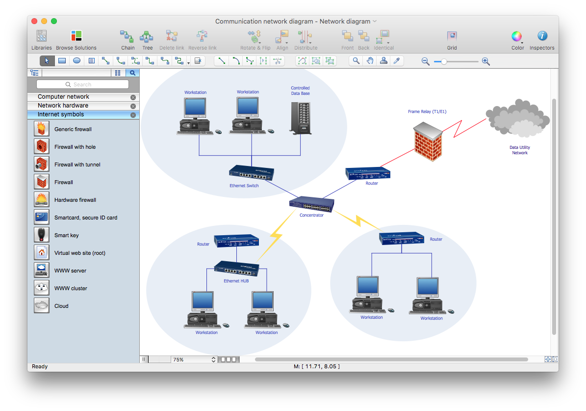
Example 6: Communication Network Diagram
This diagram was created in ConceptDraw DIAGRAM using the Computer Network, Computers and Network Isometric, Network Hardware, Logical Network Diagram, and Computer Peripheral Devices Library from the Solution. An experienced user spent 10 minutes creating this sample.
The computer network is a system joining different computer, electronic, computing and network devices (such as computers, workstations, servers, routers, concentrators, switches, hubs, firewalls, and other equipment) via cable or wireless connections, and providing communication and data exchange between these devices. The network devices or network nodes pass the data to each other along the data connections. For the information transmission can be used different physical phenomenon — electrical signals, light signals, electromagnetic emission. This Communication Network Diagram designed in ConceptDraw DIAGRAM software depicts example of computer network, which structure includes numerous computer and network devices. It reflects location and interactions between network composition parts for achievement the best communication result. It is important that regardless the number of computer and network devices containing at your network, you will be able always easily deal with its development and display its diagram by means of Computer Network Diagrams solution tools.

Example 7: Computer Network System Design Diagram
This diagram was created in ConceptDraw DIAGRAM using the Computer Network, Computers and Network Isometric, Network Hardware, Logical Network Diagram, and Computer Peripheral Devices Library from the Solution. An experienced user spent 10 minutes creating this sample.
The network planning and network design is an important iterative process, which suggests the careful consideration of all nuances concerning to the designed network, the choice of network technologies - you need decide it will be a wired network, wireless, or their hybrid. The process also supposes the choice of network topology and correct network equipment, and finally creation of sketch or diagram clearly depicting location of all computers and network devices (access points, routers, hubs, etc.) that will be connected to this network, as well as cabling arrangement. Thus, the main goal of the network design is to thought out it to the small details with a goal to avoid errors and reworks on the stages of network installation and use. But how to draw a network diagram quickly and easily? ConceptDraw DIAGRAM has extended the possibilities with Computer Network Diagrams solution that gives now ability to draw Computer Network Diagram of any complexity without any complications.

Example 8: LAN Topology Diagram
This diagram was created in ConceptDraw DIAGRAM using the Computer Network, Computers and Network Isometric, Network Hardware, Logical Network Diagram, and Computer Peripheral Devices Library from the Solution. An experienced user spent 10 minutes creating this sample.
A Local Area Network (LAN) is a computer network mounted on a limited territory, such as home, school, university, laboratory, office, or some other premise or building, which interconnects the computers within this defined area using the special network equipment, wired or wireless technologies. LAN is characterized by the limited number of computers and high data rate, large bandwidth and low level of transmission errors, the use of well-protected communication lines and effective mechanism of management the data exchange at the network. The configuration of network components and their connections is described by the network topology that defines requirements for the hardware, for the type of used cable, for work reliability, capability of extension, and many others. This diagram shows topology of the local area network (LAN), i.e. schematic of the physical arrangement of computers and network devices included in a given computer network, as well as their connection by communication lines.

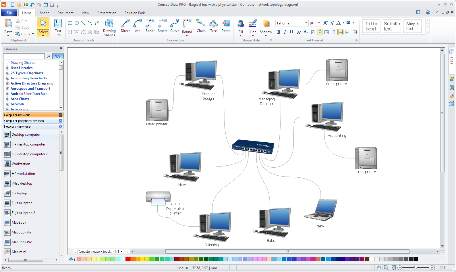
Example 9: Logical Bus with a Physical Star
This diagram was created in ConceptDraw DIAGRAM using the Computer Network, Computers and Network Isometric, Network Hardware, Logical Network Diagram, and Computer Peripheral Devices Library from the Solution. An experienced user spent 10 minutes creating this sample.
Each local area network is organized with some network topology that is a way in which devices are arranged at the network and communicate with each other. It is differentiated the logical and physical network topology, moreover the logical topology not obligatory must to be the same as a physical topology of this network. This Computer network topology diagram sample is a classic example of the network organized with a Star physical topology and Bus logical topology. It is a common case, because very often the network organized with logical bus physically is connected as a star. Each computer on this diagram is linked to the central hub device with an individual cable and all peripheral devices are connected to the appropriate computers. The bus logical topology prescribes that the spread of data packages is realized so that all network nodes receive the message and each node checks it is addressed to him or not.

Example 10: Network Topologies Diagram
This diagram was created in ConceptDraw DIAGRAM using the Computer Network, Computers and Network Isometric, Network Hardware, Logical Network Diagram, and Computer Peripheral Devices Library from the Solution. An experienced user spent 10 minutes creating this sample.
The network topology is the arranged set of different elements of a computer network, such as nodes (computers, electronic devices, network equipment, etc.) and links. The network topological structure can be represented physically or logically. If the logical topology describes the data flows within a network, which not depend from the network's physical design, the physical topology displays in details the placement of all network's components, depicts the precise location of all computer and network devices, and cables linking them. Two networks with a same logical topology can differ by physical interconnections, transmission rates, distances between nodes, and signal types. It is known eight types of network topologies: Star, Bus, Ring, Point-to-point, Mesh, Tree, Daisy chain, and Hybrid. This sample demonstrates a variety of kinds of computer network topologies. You can observe and compare schematics of the Fully Connected network topology, Mesh network topology, Start network topology, Common Bus topology, and Ring network topology.

Example 11: Network Vaccine Architecture
This diagram was created in ConceptDraw DIAGRAM using the Computer Network, Computers and Network Isometric, Network Hardware, Logical Network Diagram, and Computer Peripheral Devices Library from the Solution. An experienced user spent 10 minutes creating this sample.
Different kinds of viruses, Trojans, worms, bots and other malwares represent a serious threat for software of computers and other electronic devices. The worms are ones of the most widespread. They are the type of malwares, which are able to self-spread through the local networks and the Internet by creating the copies of themselves. Worms are independent software that do not require other files or host programs, as well as a human's assistance for malicious work and distribution. They enter to the computer to attack it through a system's vulnerability. This computer network diagram example was drawn on the base of the illustration from the webpage "Software & System Assurance. Autonomic Software Patching" placed on a website of the Network Security Lab at Columbia University's Computer Science Department. It depicts the network worm vaccine architecture that is well-known and incredibly useful system developed for automatic patching and defense the systems and networks from the attacks of worms or other network threats.

Example 12: Physical LAN Topology Diagram
This diagram was created in ConceptDraw DIAGRAM using the Computer Network, Computers and Network Isometric, Network Hardware, Logical Network Diagram, and Computer Peripheral Devices Library from the Solution. An experienced user spent 10 minutes creating this sample.
The physical topology of the local area network (LAN) defines the physical location of its computers and other network components, as well as the cables that connect these devices. The diagram of the physical network topology on the paper or on the monitor's screen reflects schematic of geometrical arrangement the network nodes and their physical connections in a form of communication lines connecting them in a local area network. ConceptDraw DIAGRAM enhanced by Computer Network Diagrams solution with its libraries of ready-made vector objects and predesigned templates and samples available from the ConceptDraw STORE, is the best software for drawing the physical topology diagrams for the LANs of different kinds. This can be as simple schemes for the networks located in small spaces, like as on this sample, and complex physical network topology diagrams constructed for the large office buildings with several floors, a lot of premises and numerous workstations connected to the network.
Inside


What I Need to Get Started
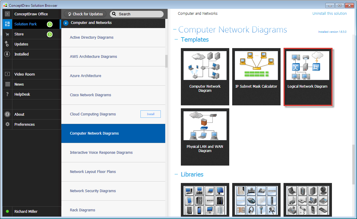
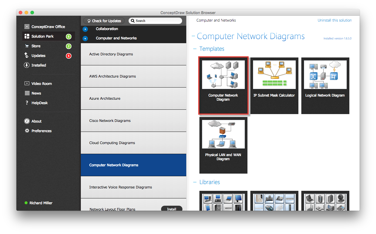
Both ConceptDraw DIAGRAM diagramming and drawing software and the Computer Network Diagrams solution can help creating the network diagrams you need. The Computer Network Diagrams solution can be found in the Computer and Networks area of ConceptDraw STORE application that can be downloaded from this site. Make sure that both ConceptDraw DIAGRAM and ConceptDraw STORE applications are installed on your computer before you get started.
How to install
After ConceptDraw STORE and ConceptDraw DIAGRAM are downloaded and installed, you can install the Computer Network Diagrams solution from the ConceptDraw STORE.

Start using
To make sure that you are doing it all right, use the pre-designed symbols from the stencil libraries from the solution to make your drawings look smart and professional. Also, the pre-made examples from this solution can be used as drafts so your own drawings can be based on them. Using the samples, you can always change their structures, colors and data.

How To Create a Logical Network Diagram using ConceptDraw DIAGRAM
- Choose a Logical Network Diagram template from the STORE under the Computers Network Diagrams solution to create a new document.
- To create a Logical Network Diagram, insert predefined libraries objects into the document. You can link them using the Curve or Bezier Connector tools, add texts to the objects, and add notes to provide a more detailed description if necessary.
- Use callouts and group boxes to show network areas and/or groups.
- Print and keep the document for reference.
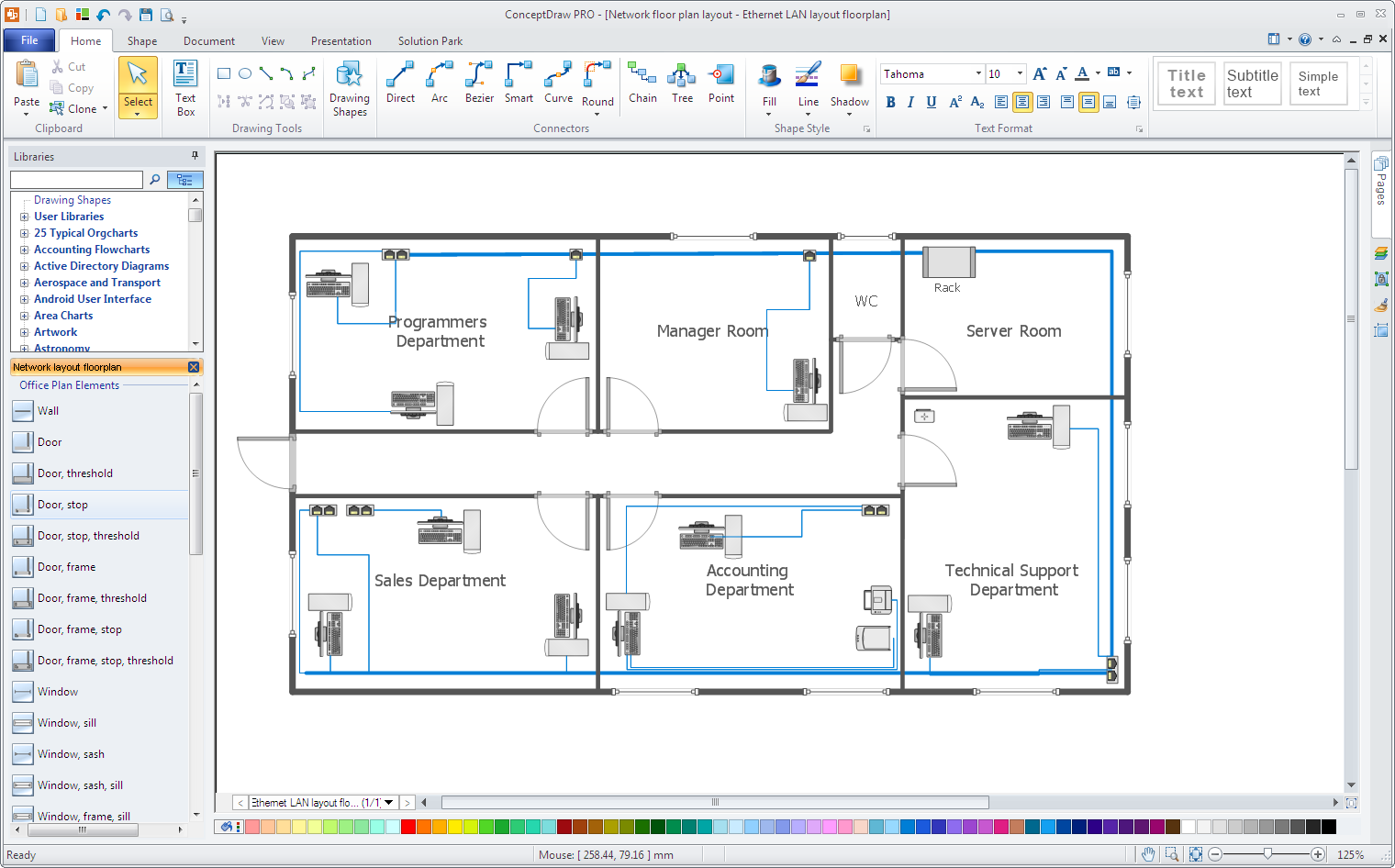
How To Create a Network Communication Diagram
A Network Communication Diagram shows primary corporate network communications.
- Use the Computer Network Diagram template from the STORE under the Computers Network Diagrams solution to create a new document. A new document with a simple office plan will be created.
- To create a Communication Network Diagram, insert predefined libraries objects into the document. You can link them using the Direct Connector tool, add texts to the objects, and add notes to provide a more detailed description if necessary.
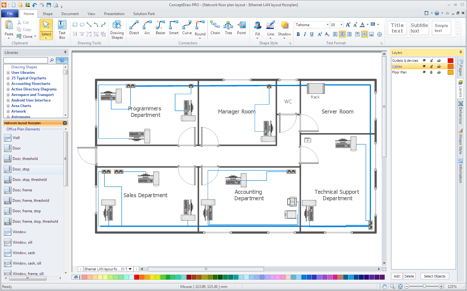
How To Create a Network Layout Diagram
The Network Layout Diagram is used to show the location of your company network equipment. To create a Physical Network Diagram, you should draw your office layout and your network equipment.
- Use the Network Layout Diagram template from STORE under the Network Layout Floor Plan solution to create a new document. A new document with a simple office plan will be created.
- Use floor plan elements to draw the layout of your office.
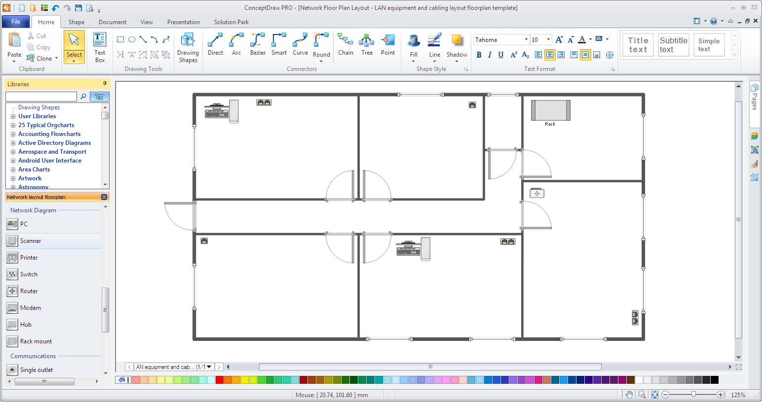
- Add network equipment on your office plan and add notes to your equipment.
- You may want to use a different layer for your equipment; by using layers you are able to show/hide your network equipment with just one-click. You can do this by turning the Layers dialog on and then dragging and dropping your network objects onto the other layer. Now you can show or hide your equipment by simply switching the corresponding layer on/off.
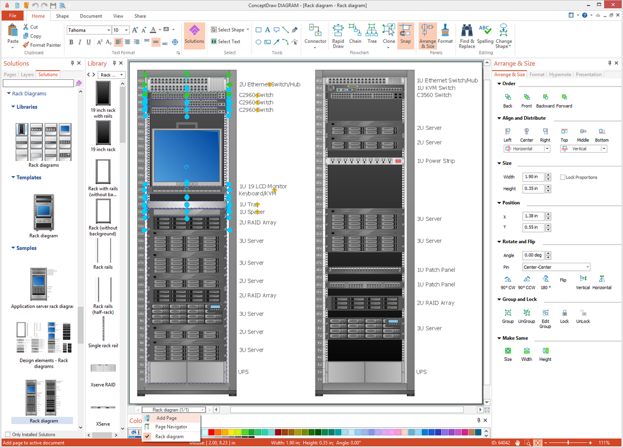
How To Create a Rack Diagram
A Rack diagram is used for creating documentation about your servers.
- Use the Rack Diagram template from STORE under the Rack Diagram solition to create a new document. A new document with rack, KVM switch, Ethernet switch, and 2U server elements will be created.

- Use other network equipment objects from the Rack Elements Library to enhance your diagram. Since there is network equipment contained in racks, you can use notes, callouts, or custom properties (user defined properties) to enter more detailed information about the item. Notes and callouts can be found in ConceptDraw DIAGRAM libraries and custom properties can be added to any drawing object. To add a custom property, right-click on any ConceptDraw object and choose Add Custom Property.
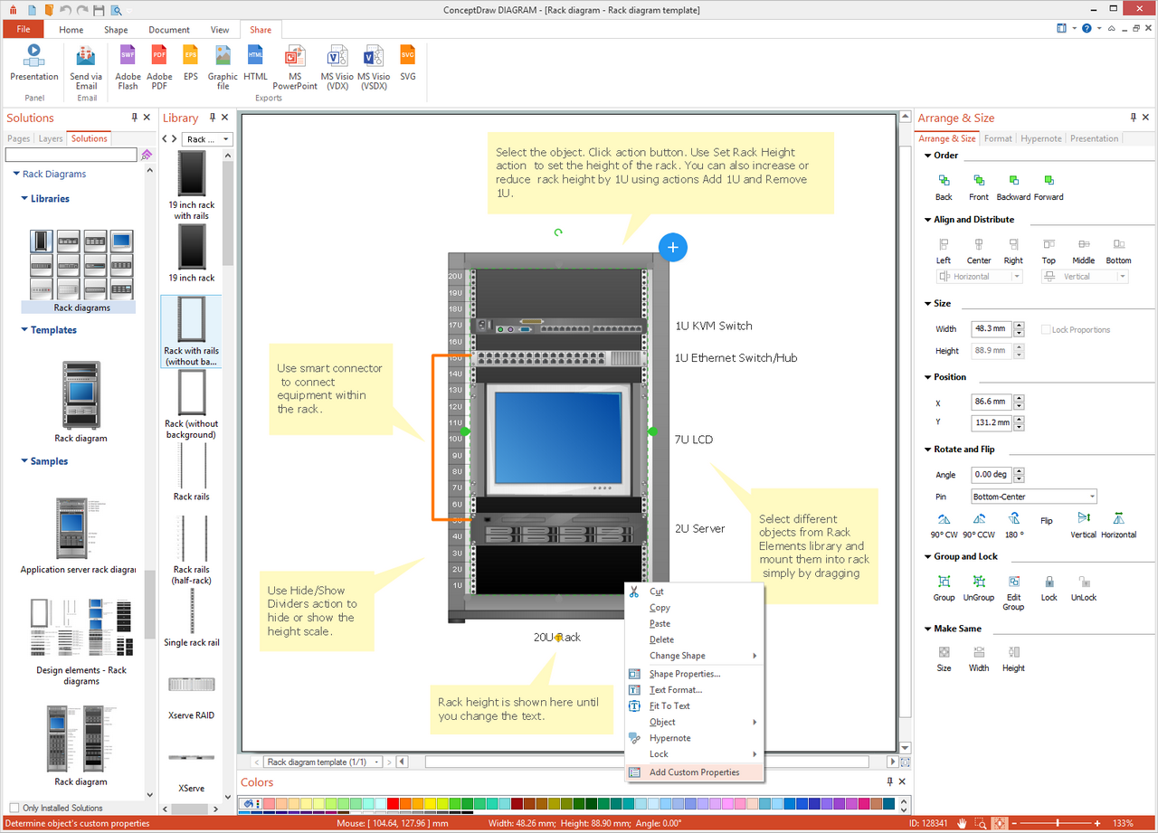
- To change the rack height, select the rack and click Action (a small blue arrow located in the upper-right corner of the rack). Several options for changing the rack size are available.
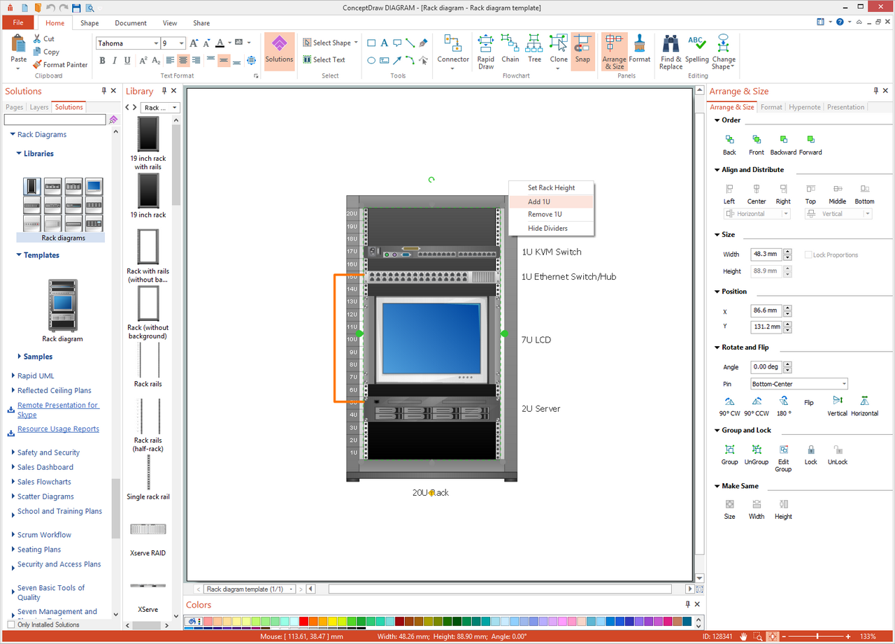
- To document another rack and its equipment, add a new page by choosing Add Page from the Page Bar menu. Add Rack from the Rack Elements Library and then insert other necessary equipment.
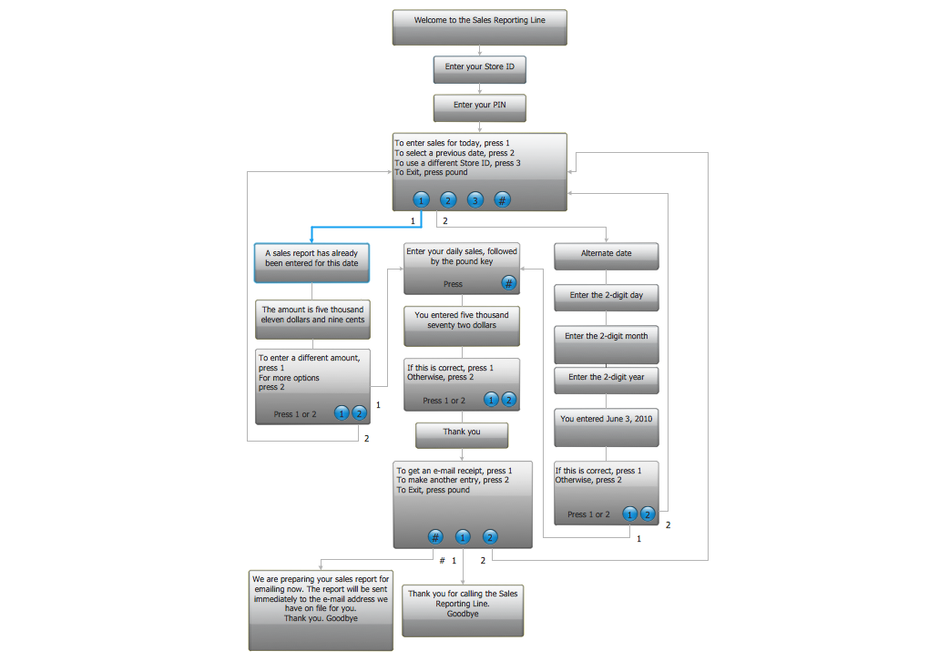
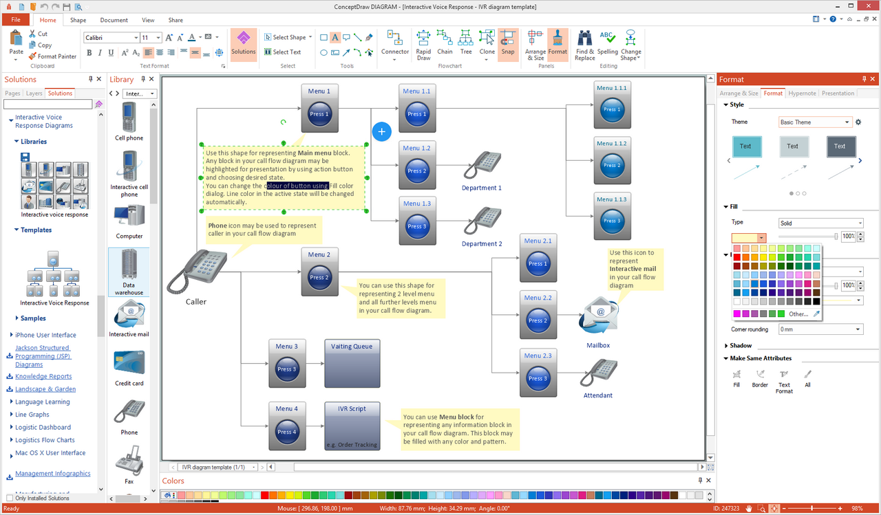
How To Create an Interactive Voice Response Diagram
Use ConceptDraw DIAGRAM to document your Interactive Voice Response map and internal phone numbers.
- Use the Interactive Voice Response template from ConceptDraw DIAGRAM Template Gallery under the Computers & Networks category to create a new document. A new document will be created containing a simple IVR diagram.
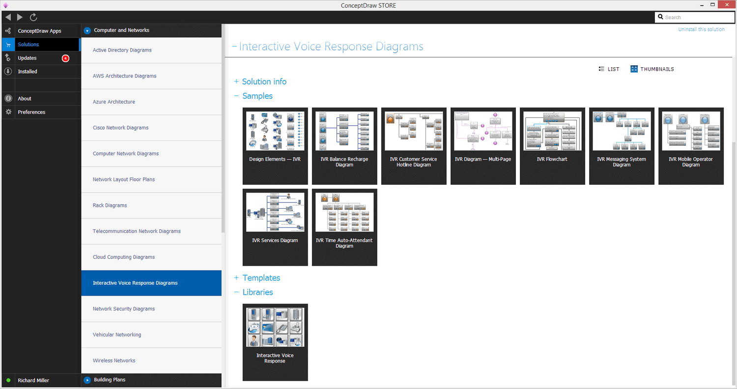
- Change numbers or add new elements from the Interactive Voice Response Library. Use the Smart Connector tool to show how your voice menu is organized.
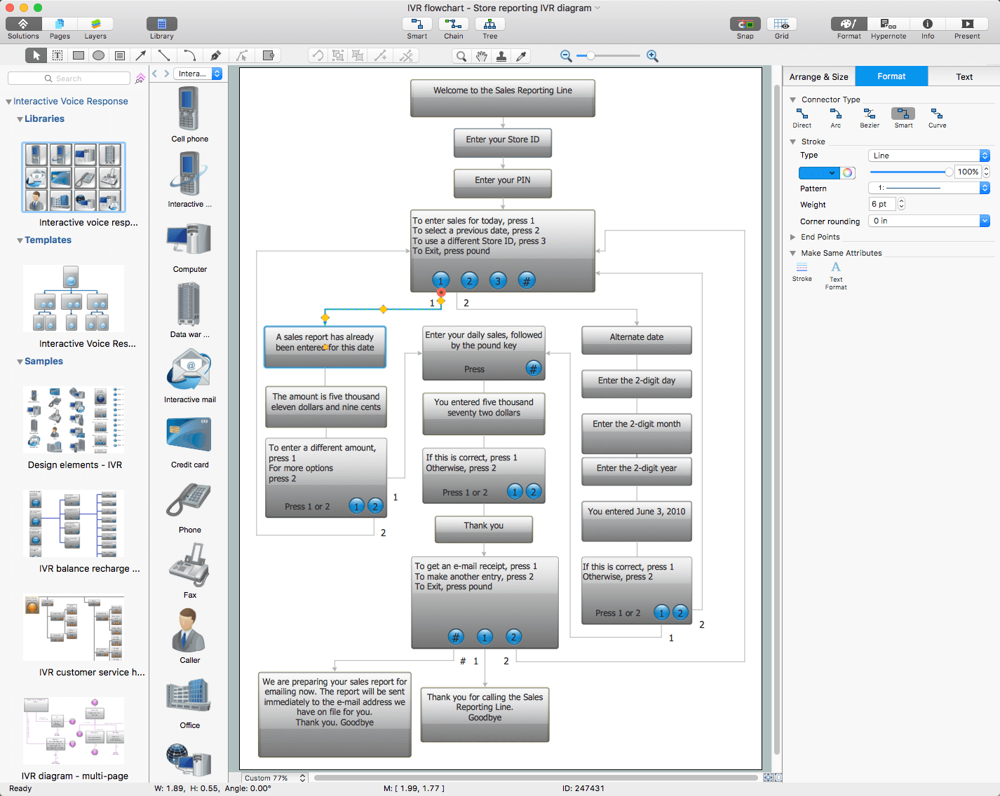
- Remove comments and use Menu block for representing any information block in your call flow diagram. You can change the color of buttons and blocks using Fill color dialog.
About
Benefits: With the Computer and Networks solution you can create professional-looking network diagrams quickly and easily allowing you to clearly represent and communicate network architecture, topology, and design to engineers, stakeholders and end-users. Also allows you to draw logical, physical, cable network, rack, Cisco network topology, and active directory domain services diagrams.
Objective: Visually communicate computer networks architecture, topology and design to simplify and accelerate understanding, analysis, and representation.
Solution Purpose: Drawing common computer network diagrams such as active directory domain services diagrams, Cisco network topology diagrams, physical LAN & WAN diagrams, logical network diagrams, Interactive Voice Response diagrams, network cable diagrams, and rack diagrams.
Intended For: Computer network engineers and designers who need to illustrate the network documentation with computer network diagrams.
Products and Methods: ConceptDraw DIAGRAM is a powerful and intelligent vector graphics engine that can be used for basic diagramming. The shape libraries contain ready-to use icons of computers, servers, network devices, standard symbols and smart connectors for the quick and easy arrangement of network diagrams. ConceptDraw MINDMAP can be used to structure and organize more detailed information about all equipment in a more visual manner and gives the option to produce dynamic presentations.

Solution Reference
Draw logical network diagrams such as physical LAN & WAN diagrams, network cable diagrams, rack diagrams, Cisco network topology diagrams, active directory domain services diagrams, and Interactive Voice Response diagrams for the visualizing of computer networks architecture, topology and design details.
Toolbox 1. Designing a Network Logical Structure
Logical network structure; basic network hardware and components; mapping of the data flow between the nodes; transmission rates; signal types.
| Tasks | Actions | Products |
| Active Directory Diagram | In ConceptDraw DIAGRAM, use Active Directory Diagram template | DIAGRAM |
| Cisco Network Diagram | In ConceptDraw DIAGRAM, use one of Cisco Network Diagram, Cisco Networking, Cisco Products or Cisco Security template | DIAGRAM |
| Computer Network Diagram | In ConceptDraw DIAGRAM, use Computer Network Diagram template | DIAGRAM |
| Logical Network Diagram | In ConceptDraw DIAGRAM, use Logical Network Diagram template | DIAGRAM |
Toolbox 2. Developing a Network Communication Plan
Floor plan layout with network nodes, data links, server rooms, etc.
| Tasks | Actions | Products |
| Network Communication Plan | In ConceptDraw DIAGRAM, use Network Communication Plan template | DIAGRAM |
Toolbox 3. Designing a Physical Network Diagram
Floor plan layout of network components and computers.
| Tasks | Actions | Products |
| Network Layout Diagram | In ConceptDraw DIAGRAM, use Network Layout Diagram template | DIAGRAM |
| Physical LAN and WAN Diagram | In ConceptDraw DIAGRAM, use Physical LAN and WAN Diagram template | DIAGRAM |
| Cisco Network Diagram | In ConceptDraw DIAGRAM, use Cisco Network Diagram template | DIAGRAM |
| Wireless Network Diagram | In ConceptDraw DIAGRAM, use Wireless Network Equipment template | DIAGRAM |
Toolbox 4. Designing and Mapping Network Hardware
Designing and mapping server hardware, analyzing existing hardware, planning network extensions.
| Tasks | Actions | Products |
| Rack Diagram | In ConceptDraw DIAGRAM, use Rack Diagram template | DIAGRAM |
Toolbox 5. Designing a Service and Application Network for Servers
A list of running services; consolidating servers on virtual machines; load balancing; creating a rack diagram.
| Tasks | Actions | Products |
| Server Services | In ConceptDraw MINDMAP, use input template Server Services from Universal Diagramming — Computers & Networks input tab | MINDMAP |
Toolbox 6. Designing and Developing an Interactive Voice Response System
Visual design and development of an Interactive Voice Response system.
| Tasks | Actions | Products |
| Interactive Voice Response Diagram | In ConceptDraw DIAGRAM, use Interactive Voice Response Diagram template. | DIAGRAM |
Visual Documentation of a Corporate Computer Network
To achieve high-quality documentation of network infrastructure, it is necessary to include the overall network structure topology, a communication scheme, the layout of the main devices, the scheme arrangement of servers in server racks, the list of installed services, services and databases for each server, and the scheme of corporate PBX.
The Computer and Networks solution provides a set of templates for documenting such office network infrastructure. It includes 5 templates and sample documents for more than 10 different diagrams. They are:
- Network Logical Structure Diagram
The Network Logical Structure Diagram is designed to show the logical organization of a network. Shows the basic network components, network structure, and determines the interaction of all network devices. The diagram displays basic devices and zones: Internet, DMZ, LAN, and group. Clarifies what network equipment is connected, describes the major nodes in the network, gives an understanding of the logical structure of the network as well as the type of interaction within the network.
- Network Communication Plan
The Network Communication Plan is intended to document the main locations of communication lines. This scheme simplifies further communication service and allows you to plan remodeling of the office. The plan is created in two steps: first is to draw a general floor plan to mark rooms and server room; then to mark network communication lines, add sockets, etc.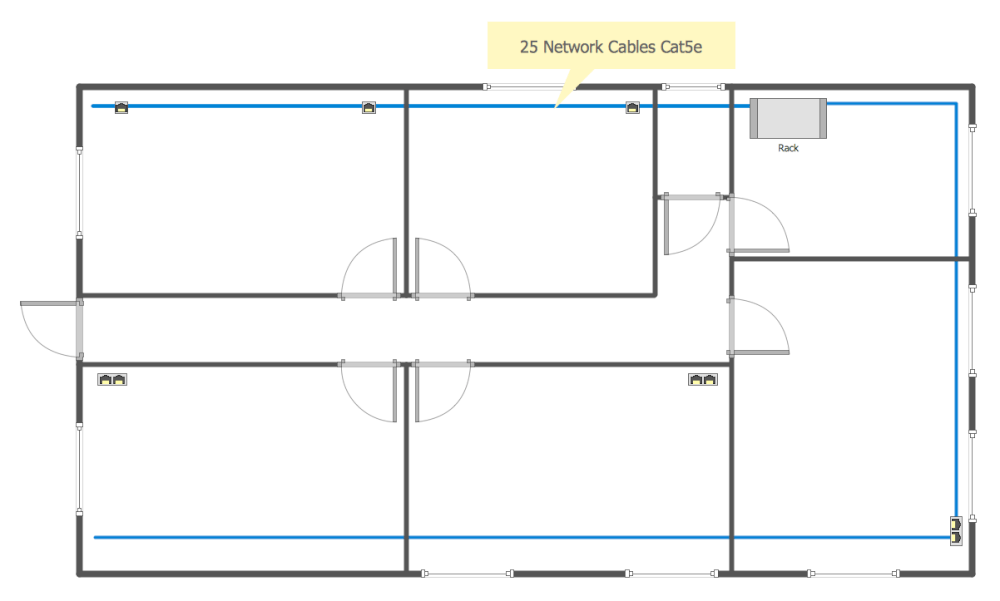
- Common Network Diagram
The Common Network Diagram shows the set of actual connected devices and is drawn from the plan of the office which shows the available network connections.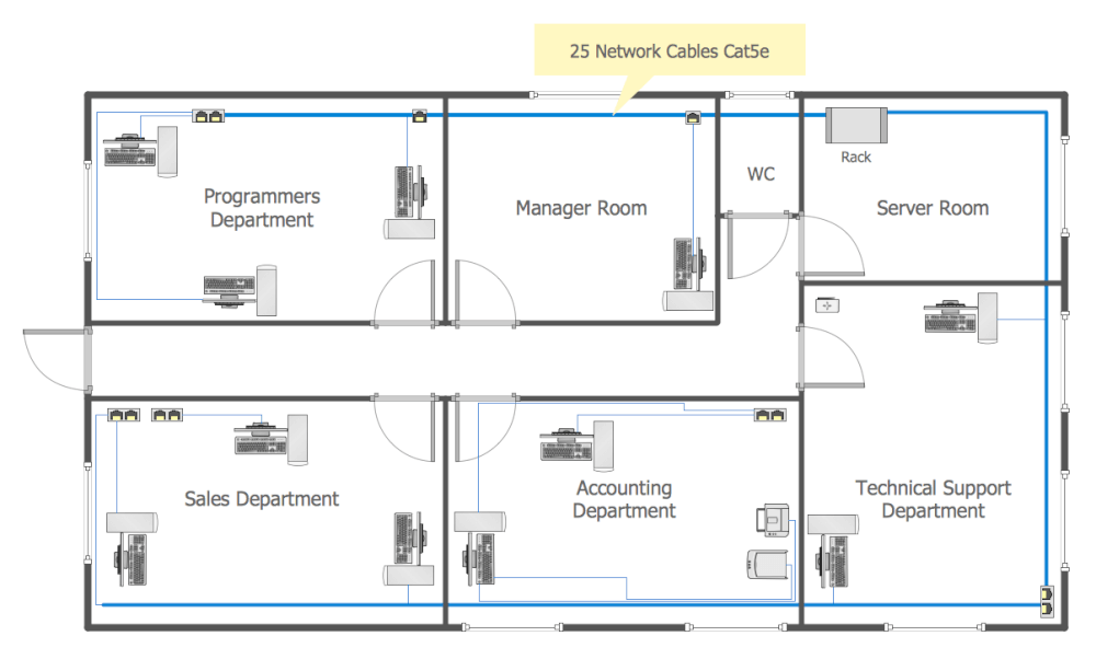
- Rack Diagram
The Rack Diagram is intended to document server hardware. Availability of documentation makes it easier to deal with emerging problems, to connect new equipment, and to analyze and plan for network expansion. To create a Rack Diagram, draw a diagram of the rack with a set of installed equipment such as servers, switches, UPS’s.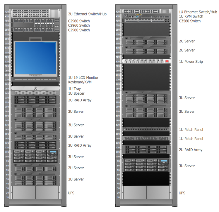
- Server Services Scheme
The Server Services Scheme is intended to document all utilized services and database servers. The document contains a list of running services and virtual machines for a particular server and stores the hardware configuration of the server. This type of scheme allows you to visually display the running services and to assess the possible load on the server.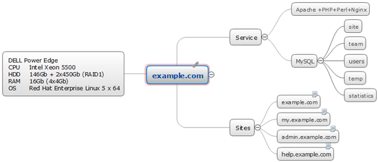
- Interactive Voice Response Scheme
The Interactive Voice Response Scheme stores a set of codes to switch the internal PBX systems as well as codes for an Interactive Voice Response system.