What is a Local Area Network? Examples of LAN Diagrams
A local area network (LAN) is a network that connects a group of computers and other devices one to another in a small scope, typically in a 1-kilometer radius. Most often it is a network created within one building, for example, a home, school, university campus, research facility, laboratory, office, or any other enterprise.
Usually, LAN comprises computers and peripheral devices such as printers, scanners, IoT devices, and others linked to a local domain server. All local network appliances can use shared devices or disk storage, send and receive information. For example, multiple users can scan or print to one shared scanner or printer, take access to one file and edit it without a need to make a copy. It is also possible to connect other modern devices like stereos, speakers, smartphones, smart TV, thermostats, cameras, lighting, and others.
Security measures like firewalls, network access control, and encryption are implemented to protect LANs from unauthorized access.
There are two main types of LANs:
- Client/server LAN — the most popular type of network for business, education, research institutions, and government, which consists of several devices (clients) connected with cables or through a wireless connection to a central server that manages file storage, databases, network traffic, and access to devices and applications;
- Peer-to-peer LAN — typically has a small size and perfectly suits for a home network, it doesn't have a central server and all devices are equal in the network, share resources and data through a wired or wireless connection to a switch or router.
What is a Local Area Network?
Local Area Network (LAN) differs from other kinds of networks by its size, topology, and transmission technology. LAN can comprise from one or two users in a small office to hundreds and thousands of users or devices within a large enterprise or educational institution.
The LAN's topology determines how devices are interconnected in a network. The most common topologies are:
Star network topology — each device is connected directly to the central hub or switch, which correct operation impacts the work of the whole network;
Bus network topology — all devices are connected to a single cable and receive the same signal simultaneously, it is cost-effective but can suffer from signal loss over long distances;
Ring network topology — each device is connected to exactly two other devices forming a single continuous pathway for signals and allocating all devices equal access to network resources, making them difficult to configure and less popular;
Mesh network topology — each device is connected to other multiple devices and several devices can transmit data simultaneously.
LANs use different technologies and protocols to connect devices within a network: Ethernet, Token Ring, FDDI, ARCNET, Transmission Control Protocol/Internet Protocol (TCP/IP), User Datagram Protocol (UDP), etc. Currently, Ethernet is the most used protocol for wired LANs and WiFi for wireless. Their combinations are also widespread.
One popular kind of LANs is a virtual LAN, which enables to group logically the network nodes and divide networks without changes in their infrastructure. For example, it is useful to logically separate the computers of multiple departments in one enterprise, which are connected to the same switch, and form the corresponding virtual LANs. This helps to simplify network operation and management, control and improvement of the traffic.
Components of LAN Network
The main components of a Local Area Network include hardware components and software components, which operate together to share data and resources efficiently within a LAN.
Hardware components determine the physical infrastructure of a LAN and comprise:
Devices — computers including desktop computers, laptops, mobile devices, tablets, smartphones, which are the nodes of a LAN, network devices;
Servers — high-powered computers that store, share, and manage network resources and data;
Additional devices like printers, file servers, application servers;
Network Interface Cards (NICs) or network adapters — hardware devices responsible for establishing a physical connection to the LAN;
Hubs — devices that connect multiple computers together within a small LAN;
Switches — devices that provide multiple ports to connect computers of a large LAN with complex network topology, ensure their communication with each other, and manage data flow by forwarding data packets to the recipient device;
Routers — connect multiple networks, analyze and route data packets between the LAN and other networks or the internet;
Wireless Access Points (WAPs) — allow devices to connect to the LAN using Wi-Fi technology;
Transmission media — cables and connectors used to establish wired connections between LAN devices and provide the physical medium to transmit data between them;
Firewalls — hardware devices that protect LANs from unauthorized access;
Network cabinets and racks where networking equipment is organized.
Software components provide a comprehensive networking environment, secure data transmission, and network management working jointly with the hardware components. They include:
network protocols like Ethernet, TCP/IP that provide certain rules and standards to govern data transmission, addressing, and managing within the network;
Network Operating System (NOS), which provides network services, network managing and controlling, and is a base to configure network settings, allocate resources, and manage user accounts;
network management software that helps to monitor, control, and manage network operation, optimize performance, and troubleshoot network configurations;
network security software like software firewalls, antivirus software, encryption tools, intrusion detection and prevention systems (IDS/IPS);
network services like remote access to network resources, file sharing, instant messaging, video conferencing, web browsing that enhance collaboration and communication within the LAN;
application software like text processors, presentation tools, spreadsheets operating on devices connected to the network and allowing users to utilize network resources and perform tasks efficiently.
Advantages and Disadvantages of the LAN
Advantages of LAN:
sharing resources like servers, printers, scanners, and other peripheral resource;
sharing a licensed software installed on one central PC;
sharing files;
centralized data store in one central location with access for each network user;
ability to use a single wired or wireless Internet connection by several devices;
reduced cost for equipment and software;
more easy and quick communication;
high data security;
controlled and restricted access to the network due to security tools.
However, LANs also have some disadvantages:
cover limited area;
high set up cost, especially of wired LANs;
privacy violations — LAN administrator has the right to access all network nodes from a central server;
necessity of network maintenance by LAN administrator;
data security threat, because a virus on one node can fast spread to the entire network, destroy the system, and wipe out the data.
How does LAN Work?
LAN is created based on various network components and protocols, which structure data and provide their transmission and communication in small units or packets called data frames. Each network device has its unique identifiers — a Media Access Control (MAC) address that specifies its physical location in a LAN and is used to address it, and an internet protocol (IP) address that defines its global internet-accessible identity. Devices communicate with one another within a LAN using MAC addresses. Each data frame includes both sender’s and receiver’s MAC addresses and other data.
Currently, the most used LAN protocols are Ethernet, Wi-Fi, and their combination. Ethernet is a protocol that uses Ethernet cables and wires to establish a physical network connection of devices to an Ethernet hub, switch, or router, while Wi-Fi is a protocol ensuring wireless network connection via radio waves. Ethernet cables (twisted pair copper, coaxial, or fiber optic) are connected to network interface cards (NICs) in devices and computers.
Most LANs connect to the Internet via a router and the simplest LANs require only it. More complex LANs, according to their size, use hubs or switches to connect multiple devices in a network and to send data directly across the network and to the server. Switches receive data frames from connected devices and send them only to defined recipients according to specified MAC addresses, not to all devices.
Not all LANs are connected to the Internet. LANs without an Internet connection use a switch to exchange data and take access to shared files or devices like servers, printers, scanners, IoT devices, desktop computers, laptops, etc. It is incredibly useful for offices and enterprises. At the same time, the non-Internet-connected LANs can use the same networking protocols as connected ones.
Virtual LANs (VLANs) typically use one router with one Internet connection and split up virtually a physical network traffic between several networks using software, not hardware.
How to draw Local Area Network Diagram
A local area network can serve for many hundreds of users. Typically, it includes many wires and cables that demand a previously designed network diagram. These diagrams are used by IT professionals to visually document the LANs' physical structure, construction, and arrangement.
Network Logical Structure Diagram is designed to show the logical organization of a network. It shows the basic network components and structure and determines the interaction of all network devices. The diagram displays basic devices and zones: Internet, DMZ, LAN, and group. It clarifies what network equipment is connected, describes the major nodes, gives an understanding of the logical structure of the network as well as the type of interaction within the network.
Local Area Network Diagrams visualize the communication schemes of LAN, and the network arrangement in houses, offices, and other buildings. They are used by IT professionals to visually document the LANs physical structure and arrangement.
ConceptDraw LAN Network Diagram Software Overview
Designing a LAN Network Diagram is the most useful way to project a local area network, think over the architecture, network components, their arrangement, and other details to further easily implement it at the place. ConceptDraw DIAGRAM comprises 1004 vector stencils in the 40 libraries that help you to start using software to design your own Local Area Network Diagrams. You can start with the appropriate templates and use a comprehensive set of graphics covering all elements of computer networking for designing local area network (LAN) diagrams.
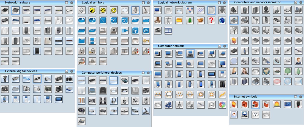
Computer Network Diagrams solution provides the following libraries with numerous vector stencils for drawing computer network diagrams and telecommunication equipment layouts:
Computer Network library contains 42 icon symbols of computer network devices and equipment.
Computer Peripheral Devices library contains 29 icon symbols of computer peripheral devices and equipment.
Computers and Network Isometric library contains 55 icons of computer and network devices and equipment.
Network Hardware library contains 37 icon symbols of network hardware.
External Digital Devices library contains 20 icon symbols of external digital devices and equipment.
Internet Symbols library contains 11 icons of Internet equipment symbols and Web shapes.
Logical Network Diagram library contains 16 icon symbols for drawing logical computer network topology diagrams.
Logical Symbols library contains 38 icons of logical symbols.
Alvarion library contains 23 icons of Alvarion devices for drawing computer network diagrams and WiMAX platform telecommunication equipment layouts.
Cisco library contains 27 icons of Cisco devices.
Comtech library contains 9 icons of Comtech devices.
Motorola library contains 10 icons of Motorola telecom devices.
Telecom Equipment library contains 16 hardware clipart icons of telecommunication devices.
Trango library contains 10 clipart icons of Trango devices.
Tranzeo library contains 11 clipart icons of Tranzeo devices.
Vertex library contains 9 clipart icons of Vertex devices.
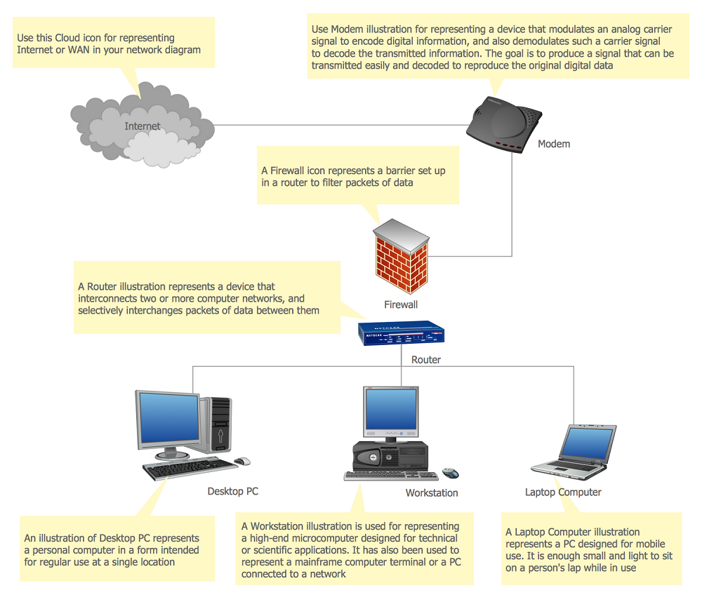
Pic 1. Computer and Network Diagrams template and symbols for designing local area network (LAN) diagrams
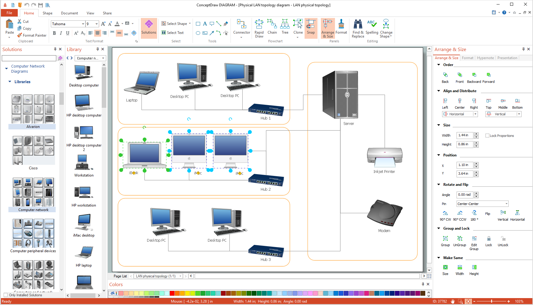
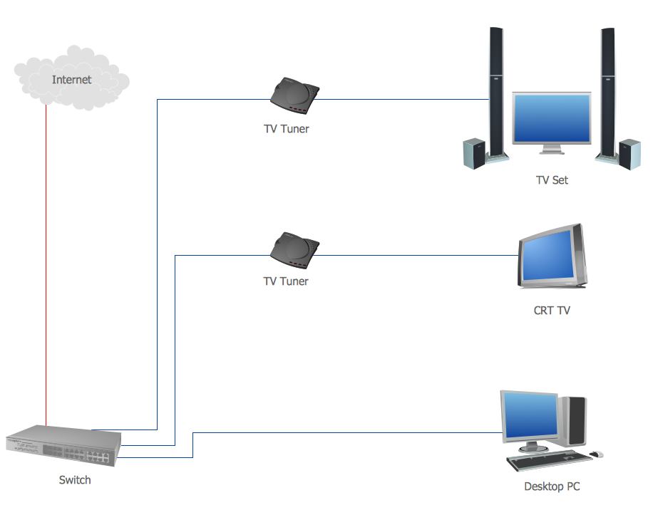
Pic 2. Designing local area network (LAN) diagram
Examples of LAN Diagrams
The samples you see on this page were created in ConceptDraw DIAGRAM using the Computer Network Diagrams solution, and they demonstrate some of the solution's capabilities and the results you can achieve.
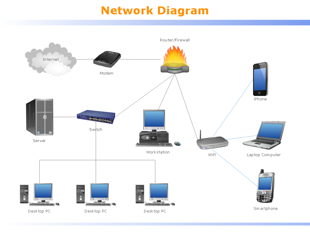
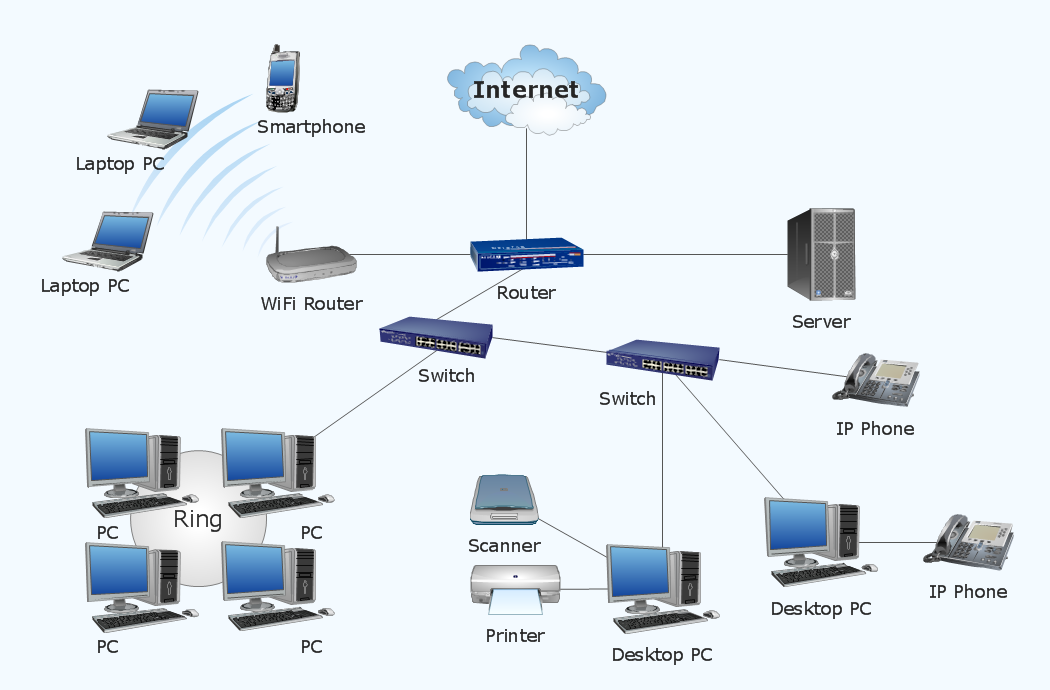
Example 4. Local area network (LAN). Computer and Network Examples
Computer Network Diagrams solution contains samples, templates and libraries of network icons that will help you to draw LAN network diagram and other types of professional-looking network diagrams quickly and easily.
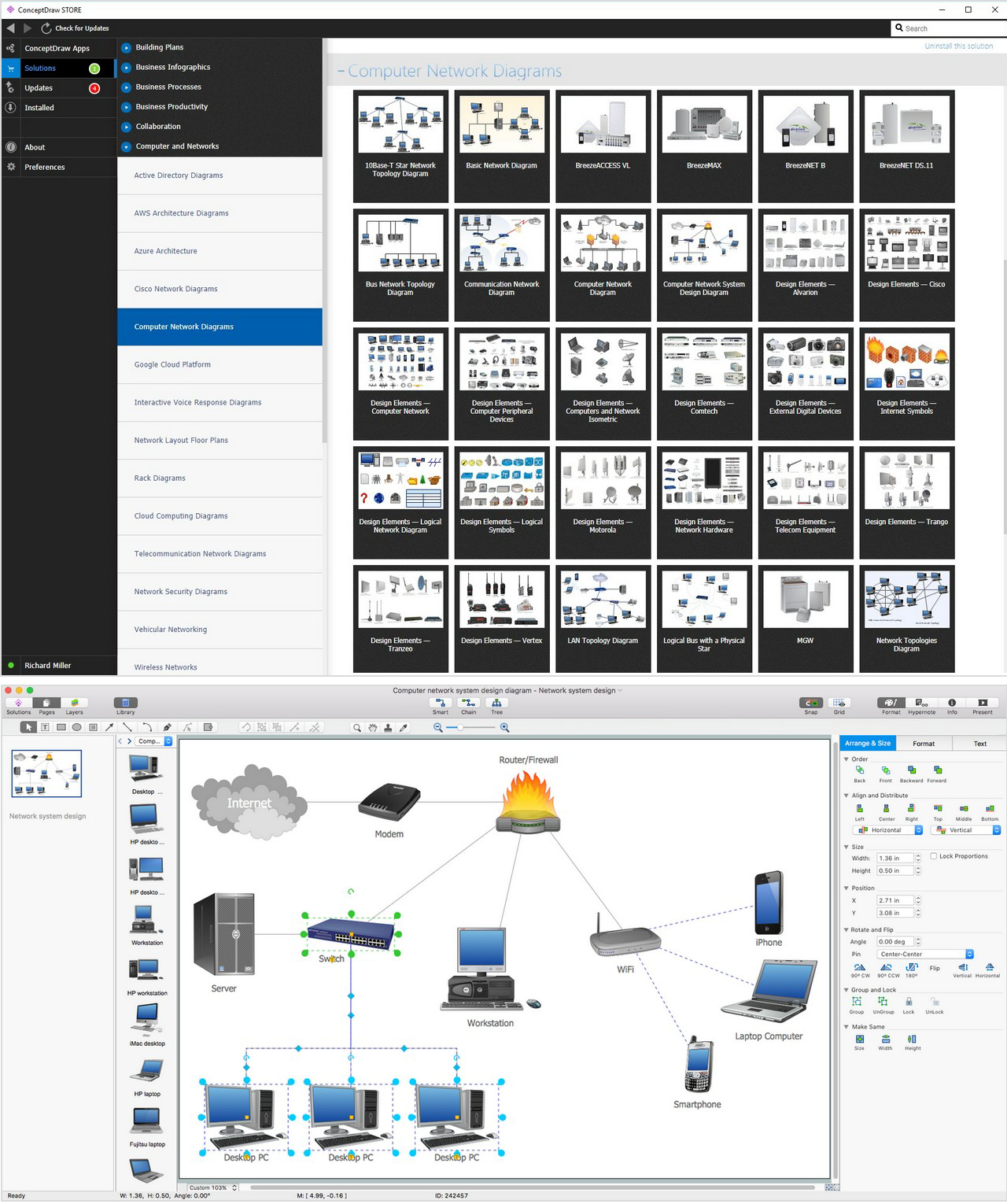
Example 5. Physical LAN Topology Diagram. Computer and Network Examples
With help of ConceptDraw DIAGRAM application you can make any desired LAN wire diagram and computer and network diagrams using the existing examples from Solution Park for making very special professionally looking charts. Try it now to simplify your work in IT and design!