Cisco Network Topology.
Cisco icons, shapes, stencils and symbols
The Cisco Network Diagrams solution uses Cisco network symbols and Cisco icons to visualize computer networks. Cisco Network Topology is the arrangement of the Cisco symbols that display scheme of computer network.
Any Cisco equipment on the network are named like node. Network diagram topology commonly designed within connected nodes. Cisco icons are worldwide acknowledged and mainly established as standard icons for network diagrams. You may use them loosely, but you may not rework them.
The Cisco Network Diagram shows how signals act on the networked devices, or how data routes on the network from one device to the other. There are number of physical network typologies that engineers use while constructing computer networks.
Cisco Network Topologies:
- Point-to-point
- Permanent (dedicated)
- Switched
- Bus
- Linear bus
- Distributed bus
- Star
- Extended star
- Distributed Star
- Ring
- Mesh
- Fully connected network
- Partially connected
- Tree
- Hybrid
- Daisy chain
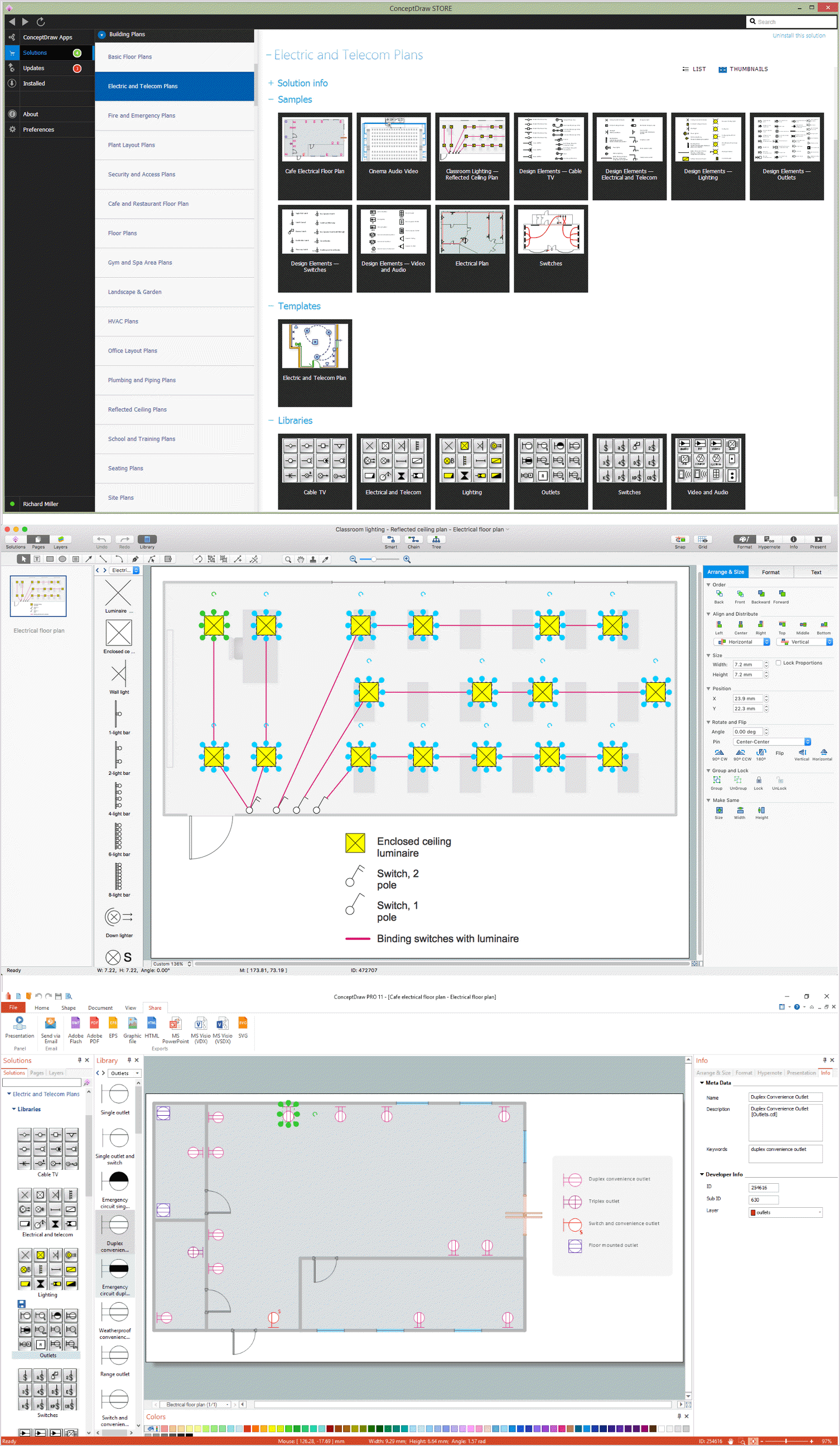
The Cisco Network Diagrams solution contains 15 stencils libraries, 508 Cisco icons, shapes, stencils and symbols.
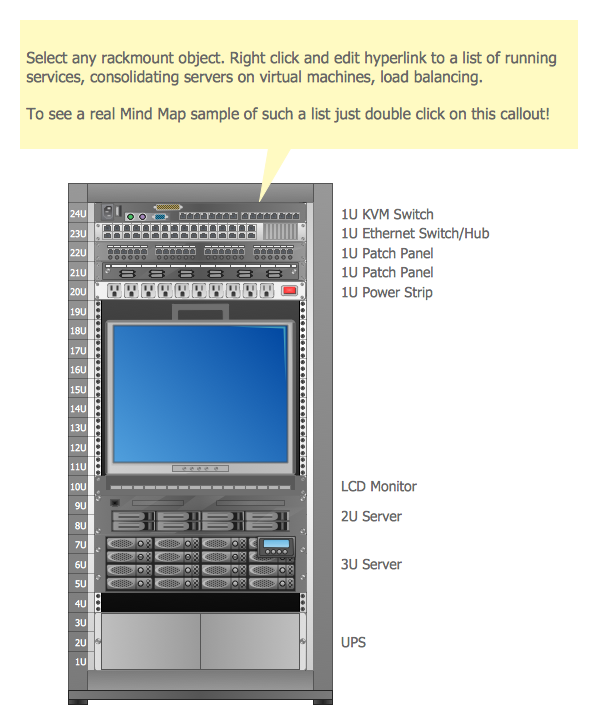
![]()
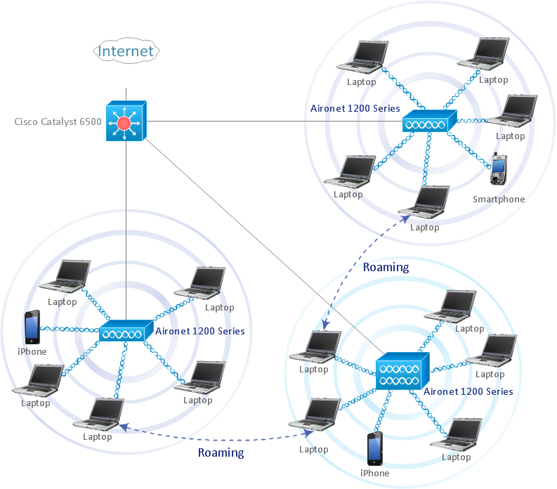
Example 1. Cisco Network Diagrams solution
The vector stencils library "Cisco network topology" contains 89 symbols of Cisco network devices and design elements for drawing computer network topology diagrams using the ConceptDraw DIAGRAM diagramming and vector drawing software.
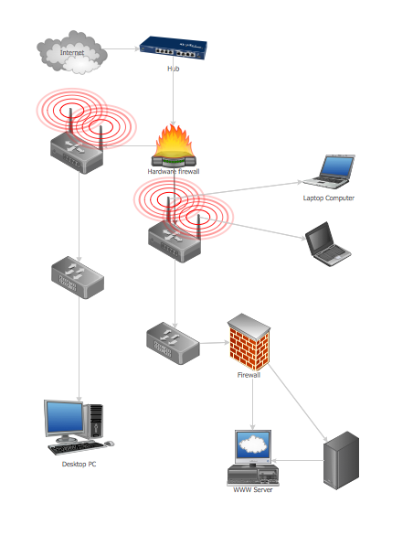
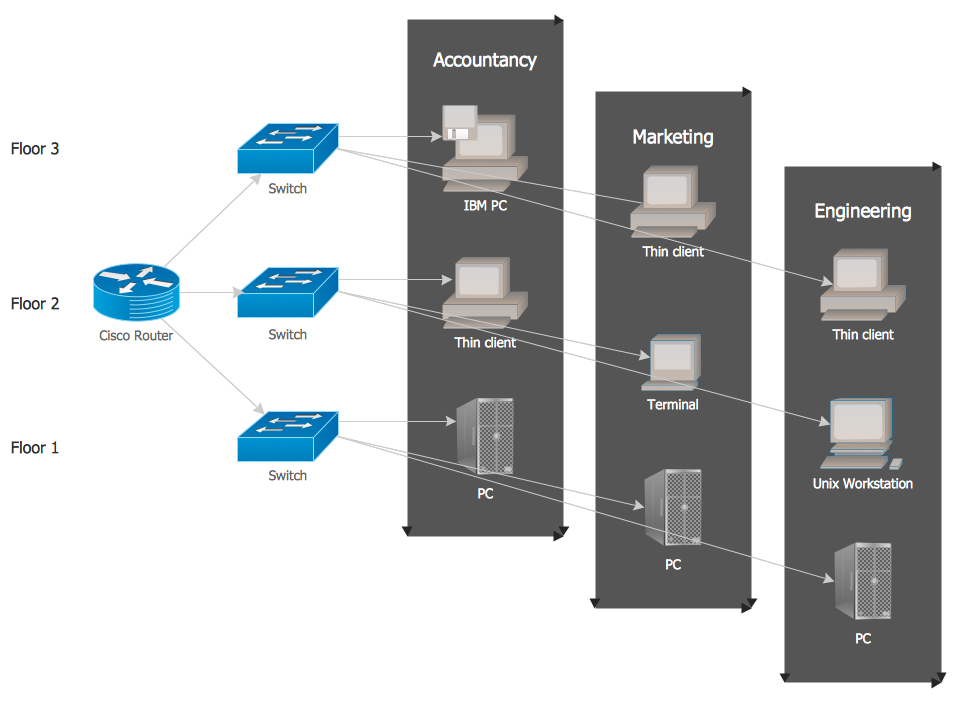
Computer network diagrams can be LAN topology diagrams, Logical Bus with a physical star, network topology diagrams, network architecture diagrams, physical LAN topology diagrams, regional cable head-end diagrams, wireless router network diagrams and many other, which can all be created with the help of ConceptDraw DIAGRAM software. There are in total eight basic topologies, which can be used nowadays for making your own Cisco Network Topology diagrams, such as: “Point-to-point” one, “Bus” topology, “Star” topology, “Ring or circular” one, “Mesh” one, “Tree” topology, “Hybrid” topology and the one called “Daisy chain”.
Point-to-point topology diagram is very simple to create using a dedicated link between its two endpoints. There are point-to-point communications associated with the two endpoints.
You can always use the right software for drawing the physical and logical network topology diagrams both for wired and wireless computer communication networks, including the “Linear bus” and the “Distributed bus” topologies.The ring topology is pretty much the same as the bus one. In such topology data travels around the ring, in only one direction. Once one node sends some particular data to another one, then this data passes through each of the intermediate nodes on the ring until it reaches its planned destination. The intermediate nodes transmit this data to keep the signal strong and every node is a peer, and there is no hierarchical relationship of servers or clients in this topology.
If one of the nodes in the ring topology is unable to transmit some particular data, then it severs communication between those nodes, which stand before and after it in the bus within this bus topology.
Mesh network is the network, which is also known as such network topology, where nodes relay data for the network. All nodes in this topology co-operate with each other in the process of the distribution of the data in the network. Mesh network type of topology can be used for both wireless and wired networks. In mesh topology, though, wireless mesh networks can be considered as a type of wireless ad hoc network that is why wireless mesh networks are related to the mobile ad hoc networks or MANETs.
Hybrid network topologies are topologies, which combine a few different types of topologies, for example, the star topology and the mesh one or the mesh one and the bus network, or the star network topology and the mesh one, etc. A tree network connected to another tree network will still be a tree network, though. A hybrid topology is always used for illustrating 2 different basic network topologies connected to each other. A daisy-chained network can be a ring one or a linear one. A ring one is used for connecting the computers at each end, which advantage is the fact, that the number of transmitters and receivers can be cut in half. And a linear network topology has a 2-way link between some particular computer and the next one.
It does not really matter which of the mentioned computer network topology diagrams you want to create, you can always do it within only a short period of time, depending on your general experience of using ConceptDraw DIAGRAM software. Downloading it today you will ensure yourself in being able to use it for making your own diagrams, great looking plans, schemes, charts and flowcharts. Especially this software will be useful in case you have to deal with the need of making different diagrams, such as Cisco network topology ones, from time to time, whether you work in IT company or somewhere else as an IT specialist. You can always save your time and so your money with ConceptDraw DIAGRAM software as it is one of only a few similar applications, providing all those needed samples and templates of ready-to-use charts, flowcharts, schemes, plans, matrices, diagrams, including the Cisco network topology ones, created by IT professionals of CS Odessa, including the web designers.
ConceptDraw DIAGRAM software is a very special tool, which is very popular and there is a reason for it: this application allows its users to make any needed drawing within only a couple of hours or even a couple of minutes, providing with the solutions and so the templates and stencils. Downloading ConceptDraw DIAGRAM software allows you to get ConceptDraw STORE as another application, which you can use for downloading any needed solutions and so the needed stencils as well as great looking templates. Each of the providing solutions include the stencil libraries (at least one) and pre-made samples, available for ConceptDraw DIAGRAM software users any time they want to use them. Cisco Network Diagrams solution provides Cisco network symbols and Cisco icons for visualizing any needed computer networks. Cisco Network Topology is the arrangement of the Cisco symbols that displays the schemes of the types of the computer networks. If you need to create any of the Cisco Network Diagrams, which show the way how signals act on the networked devices, or how data routes on the network from one device to the other, then you can use any of the number of the physical network typologies that IT engineers use for constructing computer networks. Cisco Network Topologies are, once again, Point-to-point (can be Permanent and Switched), Bus (Linear bus and Distributed bus), Star (Extended star and Distributed Star), Ring, Mesh (Fully connected network or Partially connected), Tree, Hybrid or Daisy chain. This Cisco Network Diagrams solution contains 15 stencils libraries, 508 Cisco icons, shapes, stencils and symbols.Also we can also recommend you to download the “Computer and Networks” solution, which you can find in Computer and Networks area of ConceptDraw Solution Park on this site or also in ConceptDraw STORE. This solution contains a set of examples, templates and vector design elements (including all of the necessary icons) of many network topology diagrams, so you can create your own only within a couple of hours, or even minutes, depending on your experience of using ConceptDraw DIAGRAM This Computer and Networks solution provides examples and templates as well as vector stencils library with symbols of local area network (LAN) and wireless LAN (WLAN) equipment. You can use this solution in order to draw both the logical and physical network topology diagrams for wired and wireless computer communication networks, including the network topology ones.

Example 2. Design Elements — Cisco Network Topology for Network Diagrams
(macOS, Windows)
Use the predesigned cisco icons from the Cisco Network Diagrams Solution for ConceptDraw DIAGRAM software to create your own professional looking Cisco Network Diagrams and illustrations of any complexity quick, easy and effective, and then successfully use them in your work activity.
![]()
Example 3. Cisco Network Topology example
All source documents are vector graphic documents. They are available for reviewing, modifying, or converting to a variety of formats (PDF file, MS PowerPoint, MS Visio, and many other graphic formats) from the ConceptDraw STORE. The Cisco Network Diagrams Solution is available for all ConceptDraw DIAGRAM or later users.
Icons, shapes, stencils, symbols and design elements for Cisco Network Diagrams: