Electrical Drawing Software and Electrical Symbols
An electrical drawing, is a type of technical drawing that shows information about power, lighting, and communication for an engineering or architectural project.
Electrical drawing software will assist you in drawing your electrical diagrams using standard electrical symbols, it minimize efforts and makes it very easy for beginners. Electrical symbols and smart connectors help present your:
- Electronic Circuits
- Automotive Wiring
- Electrical Schematics
- Electrical Wiring
- Cabling Layout Diagrams
- Electrical Layouts
- Circuits and Logic Schematics
- Logic Gate Diagrams
- Blue Prints
- Digital Circuits
- Parallel Circuits
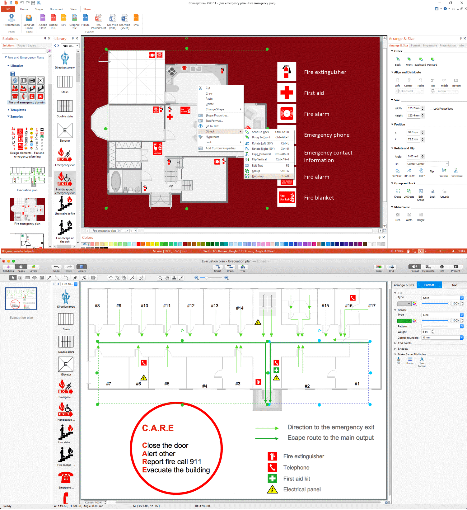
ConceptDraw DIAGRAM is a powerful software for creating professional looking electrical circuits quick and easy. For this purpose you can use the Electrical Engineering solution from the "Engineering" area of ConceptDraw Solution Park, it include thousands of electrical symbols.

Pic. 1. Electrical Drawing Software
Electrical Engineering Solution for ConceptDraw DIAGRAM provides the stencils libraries of ready-to-use predesigned vector symbols, templates and samples that make your electrical drawing quick, easy and effective.
26 libraries, 926 electrical shematic symbols of the Electrical Engineering Solution of ConceptDraw DIAGRAM make your electrical diagramming simple, efficient, and effective:
- Analog and Digital Logic library contains 40 element symbols of logic (threshold) gates, bistable current switches, current controllers, regulators, electrical generators, and amplifiers. Use it for drawing the digital and analog functions in electronic circuit diagrams and electrical schematics.
- Composite Assemblies library contains 44 element symbols of transmitters (electronic amplifiers, repeaters), static devices (rectifiers), phase shift circuits, gyroscopes, and gyrators. Use it to design the electronic circuit diagrams and electrical schematics.
- Delay Elements library contains 12 symbols of delay elements for drawing electrical schematics and electronic circuit diagrams.
- Electrical Circuits library contains 49 element of professional electrical symbols of electrical and electronic devices, including ignitors, starters, transmitters, circuit protectors, transducers, radio and audio equipment. Use it for drawing electronic circuit diagrams and electrical schematics.
- Electron Tubes library contains 36 element of electrical symbols of electron tubes. Use it for drawing electrical schematics and electronic circuit diagrams.
- IGFET library contains 18 electrical symbols of IGFET (insulated-gate field-effect transistor) elements for drawing electronic circuit diagrams.
- Inductors library contains 41 elctrical symbols of inductor elements for drawing electronic circuit diagrams.
- Integrated Circuit library contains 43 components for integrated circuit design, including transducers, rotary devices, converters, registers, analog switches, counters, registers, decoders, and multiplex transmitters.
- Lamps, Acoustics, Readouts library ontains 35 element symbols of lamps, acoustic components, electrical measuring instruments for drawing electrical schematics and electronic circuit diagrams.
- Logic Gate Diagram library contains 17 element symbols for drawing the logic gate diagrams.
- Maintenance library contains 14 symbols for maintaining electrical and electronic systems, including test, feedback and reference signals; pulses; relay contacts and coils; composite and amplifier circuits.
- MOSFET library contains 18 symbols of MOSFET (metal–oxide–semiconductor field-effect transistor) elements for drawing electronic circuits diagrams.
- Power Sources library contains 9 element symbols of power sources, power supplies and batteries for drawing the electrical schematics and electronic circuit diagrams.
- Qualifying library contains 56 qualifying symbols. Use these shapes to annotate or specify characteristics of objects in electrical drawings, electronic schematics, circuit diagrams, electromechanical drawings, and wiring diagrams, cabling layout diagrams.
- Resistors library contains 14 element symbols of resistors for drawing electronic schematics, circuit diagrams and electrical drawings.
- Rotating Equipment library contains 55 symbols of rotating equipment: converters, generators, motors, rotating machines, and their parts and labels. Use to design systems containing rotating electrical equipment (i.e., motors), armatures, brushes and related mechanical devices (brakes, gearing, clutches, interlocks).
- Semiconductor Diodes library contains 24 symbols of semiconductor diodes for drawing electronic schematics and circuit diagrams.
- Semiconductors library contains 22 symbols of rectifiers, diodes, charge transfer and electronic conduction devices, switches, cathodes, transistors, thyristors, and transceivers for semiconductor (SIS) design.
- Stations library contains 110 symbols of communications equipment, generating, transmitting and receiving stations; substations; satellites; power plants for power generation and distribution and radio relay systems.
- Switches and Relays library contains 58 symbols of electrical contacts, switches, relays, circuit breakers, selectors, connectors, disconnect devices, switching circuits, current regulators, and thermostats for electrical devices.
- Terminals and Connectors library contains 43 element symbols of terminals, connectors, plugs, polarized connectors, jacks, coaxial cables, and conductors. Use it for drawing the wiring diagrams, electrical layouts, electronic schematics, and circuit diagrams.
- Thermo library contains 14 symbols of thermoelectric elements for drawing electrical layouts, electronic schematics, and circuit diagrams.
- Transformers and Windings library contains 29 element symbols of transformers, windings, couplers, metering devices, transductors, magnetic cores, chokes, and a variometer. Use it to design the electromechanical device schematics and electronic circuit diagrams.
- Transistors library contains 30 symbols of transistors drawing electronic schematics and circuit diagrams.
- Transmission Paths library contains 43 symbols of power transmission paths, electronic circuits, bus connectors and elbows, terminals, junctions, and concentrators. Use it to annotate electrical diagrams, electronic schematics and circuit diagrams.
- VHF UHF SHF library contains 52 symbols for VHF, UHF, and SHF circuit design, including capacitance measurers, nonreciprocal devices, modulators, phase shifters, field polarization devices, and filters.
You can simply and quickly drop the ready-to-use electrical symbols from libraries into your document to create the Electrical Diagram.

Pic. 2. Electrical Engineering libraries
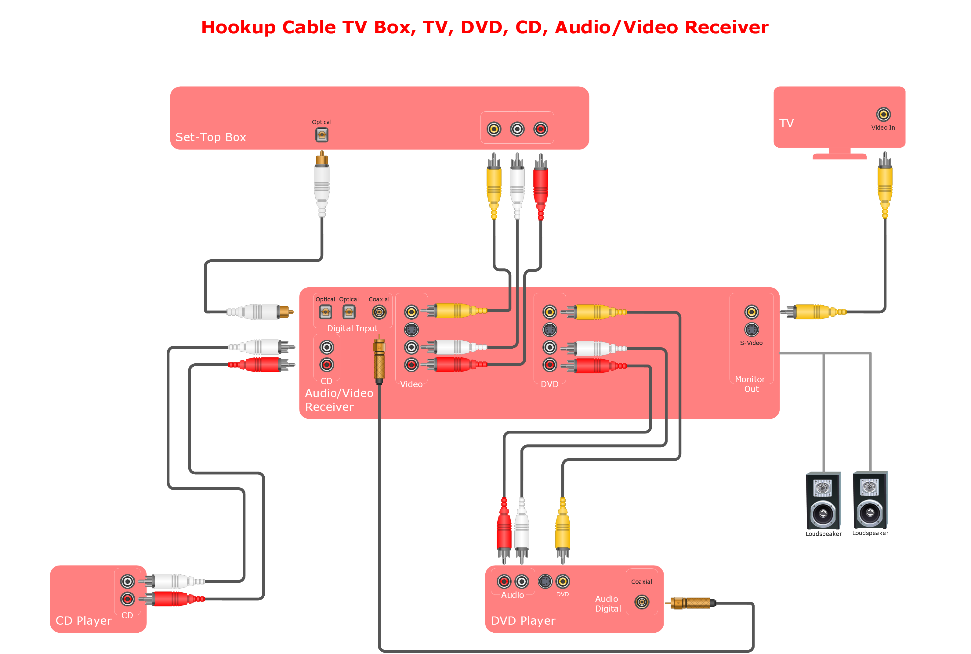
This example was created using ConceptDraw DIAGRAM with the "Electrical Engineering" Solution from ConceptDraw Solution Park.

Pic. 3. Circuit Diagram - Lamp - Electrical Symbols
The following features make ConceptDraw DIAGRAM the best Electrical Engineering Software:
- You don't need to be an artist to draw professional looking diagrams in a few minutes.
- Large quantity of ready-to-use vector electrical symbols makes your drawing diagrams quick and easy.
- Great number of predesigned templates and samples give you the good start for your own diagrams.
- ConceptDraw DIAGRAM provides you the possibility to use the grid, rules and guides. You can easily rotate, group, align, arrange the objects, use different fonts and colors to make your diagram exceptionally looking.
- All ConceptDraw DIAGRAM documents are vector graphic files and are available for reviewing, modifying, and converting to a variety of formats: image, HTML, PDF file, MS PowerPoint Presentation, Adobe Flash, MS Visio.
- Using ConceptDraw STORE you can navigate through ConceptDraw Solution Park, managing downloads and updates. You can access libraries, templates and samples directly from the ConceptDraw STORE.
- If you have any questions, our free of charge support is always ready to come to your aid.