How To use House Electrical Plan Software
Each house is an individual project that takes into account many nuances and preferences of future owners, and it is essential to carefully thought out all details. Planning and construction of any building begins with the design of its floor plan and a set of electrical, telecom, piping, ceiling plans, and other documentation. A clear plan is an opportunity to make your dreams come true, think over everything to the smallest detail, and successfully implement what you have planned.
The electrical plan is a part of the general documentation for the house construction. Planning electricity for house and designing the house electrical plan require using generally accepted electrical symbols and annotations to make them understandable for all stakeholders.
Electrical Planning
Electrical planning involves many steps from the discussion needs and desires of clients to designing and organizing the electrical systems with making a final electrical plan corresponding to the safety and efficiency statements ready to be implemented within a building. Electrical planning covers all aspects — lighting, the layout of outlets, switches, lighting fixtures, electrical panels, circuit breakers, appliances, various special equipment, protective devices, wire types and sizes, etc. It obligatory includes accounting such premise characteristics as type, size, and purpose. It should consider the optimal distribution of power and capacity to handle the expected load and safety.
Correct planning supposes the provision of convenience for users while meeting local building codes and safety standards to prevent hazards and ensure proper operation and legal compliance. An additional important point is incorporating flexibility for future expansions and modifications with the introduction of modern innovations.
To design an efficient home electrical plan, use the previously designed floor plan. Think over the right components of the electrical system, select appropriate wires, switches, breakers, outlets, safety components, surge protectors, and other electrical components accounting the application of electrical network, electrical load, used appliances and equipment. Arrange the components correctly, show the connections, and optimize circuit load distribution to prevent overloading and ensure efficient operation, reducing the risk of faults and failures. Make your plan clear and accurate, label the circuits, and indicate important metrics to simplify troubleshooting and maintenance. Inspect your plan before implementing it to ensure safety.

Example 1. House Electrical Plan Design in ConceptDraw DIAGRAM
Electrical Symbols
Electrical symbols are standardized icons used in electrical diagrams, plans, and schematics to show various electrical components, devices, and connections. Electrical symbols facilitate communication and provide a clear understanding of electrical drawings for engineers, electricians, designers, and other stakeholders. As a result, this ensures unambiguous interpretation, consistency, accuracy in electrical documentation, correct implementation of the electrical designs, and maintenance of electrical systems.
Standard electrical symbols include icons for light fixtures, switches, breakers, outlets, taps, batteries, sensors, amplifiers, detectors, and many more electrical components, devices, and appliances. A correct understanding of house electrical symbols is also vital because ensures accurate communication and correct implementation of electrical systems.
Benefits of Using Electrical Plan Software for Home Design
The use of specialized electrical plan software has a lot of benefits for home design, in particular:
speeds up the planning process;
helps to create clear and detailed electrical plans with precise placing of components;
saves time and resources significantly by offering ready-made objects and automating many tasks;
provides enhanced accuracy and quality of house electrical designs;
helps to generate clear and comprehensive documentation and reports meeting specific needs and preferences;
supports construction, inspection, and maintenance processes;
reduces the risk of errors and rework helping to catch potential issues at the stage of planning;
provides a better understanding of designs;
enhances collaboration between all stakeholders, architects, designers, builders, electricians, and homeowners;
helps to ensure compliance with electrical codes and standards;
simplifies expansion and upgrading through the integration of innovative technologies, equipment, and systems;
simplifies customization, modification, and introduction changes.
Features and Tools of ConceptDraw DIAGRAM Electrical Plan Software
Professional house electrical wiring diagram and electrical plan software is vital nowadays because typically provides a lot of tools and features, which easier drawing process and make it high-quality. ConceptDraw DIAGRAM is one such software that provides efficient basic features and tools for creating accurate, professional-looking, and compliant electrical plans and designs. These include:
user-friendly interface;
powerful drawing tools;
extensive libraries of generally accepted symbols for electrical components;
drag-and-drop functionality;
ready-made quick-start templates;
alignment options;
layer management;
options for adding legend, notes, labels, instructions, and other details;
wide import and export options for easy sharing, collaboration, communication, and editing plans.
Creating Home Electrical Plan in ConceptDraw DIAGRAM
Solutions of the Building Plans area for ConceptDraw Solution Park can help effectively to develop all variety of building plans including electrical plans quick and easy.

Example 2. Home Electrical Plan
Follow the next steps to design the Home Electrical Plan in minutes:
- Use the predesigned home floor plan from offered in ConceptDraw STORE or design your own using the libraries of Floor Plans solution from the Building Plans area.
- Drag the needed vector objects from the set offered by 6 libraries of the Electric and Telecom Plans solution, arrange and interconnect them with accounting current and future needs, allowing easy upgrading of the diagram at any time.
- Include the legend, descriptions of components, identifiers for electrical devices, indicate wiring types and sizes, operating voltage, and current ratings.
- Outline the instructions, important safety information, and installation notes on how to route wires and connect electrical components.

Example 3. Electrical Symbols
The electrical documentation helps to perform required calculations, such as load, voltage, amount of equipment and wires, and expenses. It can include electrical requirements for used equipment, local electrical codes, and specifications. The included labels and annotations help to clarify the design, check it for compliance with electrical codes, safety requirements, efficiency, and scalability, and facilitate optimization and installation.
Electric and Telecom Plans Solution also contains the collection of already predesigned templates and samples which can be used as a good base for various electrical and telecom plans. Use importing and exporting capabilities to share your house circuit diagram, electrical plan, or home wiring diagram and collaborate efficiently with all stakeholders. 
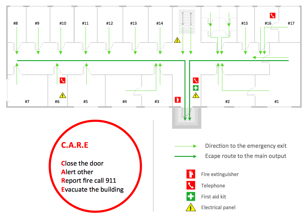
Example 4. House Electrical Plan Sample
Examples
The examples and samples you see on this page were created in ConceptDraw DIAGRAM using the tools of Electric and Telecom Plans solution from the Building Plans area. Each of them is a professional-looking Home Electrical Plan. An experienced user spent 10-20 minutes creating each included example of house electrical plan.
Electric and Telecom Plans solution includes a lot of examples of clear and detailed electrical and telecommunication plans, wiring routes, and lighting diagrams for homes, apartments, offices, and other premises. Use the Electric and Telecom Plans solution for ConceptDraw DIAGRAM to create detailed documentation including home electrical wiring diagram, electrical plans, and specifications. This solution assists in creating professional-looking Home Electrical Plans of any complexity to guide efficiently the installation process of electrical equipment and wiring, and easier their future maintenance or upgrades.
Each home electrical schematic and house wiring diagram designed with ConceptDraw DIAGRAM are vector graphic documents available for reviewing, modifying, converting to a variety of formats (image, HTML, PDF file, MS PowerPoint Presentation, Adobe Flash or MS Visio), printing, and sending via e-mail in one moment.
Conclusion
ConceptDraw DIAGRAM enhanced with the Electric and Telecom Plans solution is an efficient assistant in creating precise, reliable, compliant, and safe electrical plans, residential electrical plans and wiring diagrams for any project. It streamlines the electrical planning process, placement of lights, outlets, switches, and other electrical components, as well as wiring paths. The reliable plans ensure efficient and logical routing in compliance with the dimensions and layout of the space, the project’s complexity, specific needs, and safety standards.
The well-documented and thought-out electrical plans, house wiring schematic diagram, home circuit diagram, and other electrical documentation plans designed in ConceptDraw DIAGRAM are easy to set up and update, can be exported to different formats, and shared with builders, electricians, contractors, and other stakeholders for feedback, improvement, implementation, and maintenance.