Interior Design. Shipping and Receiving — Design Elements
Shipping and receiving — Design elements library
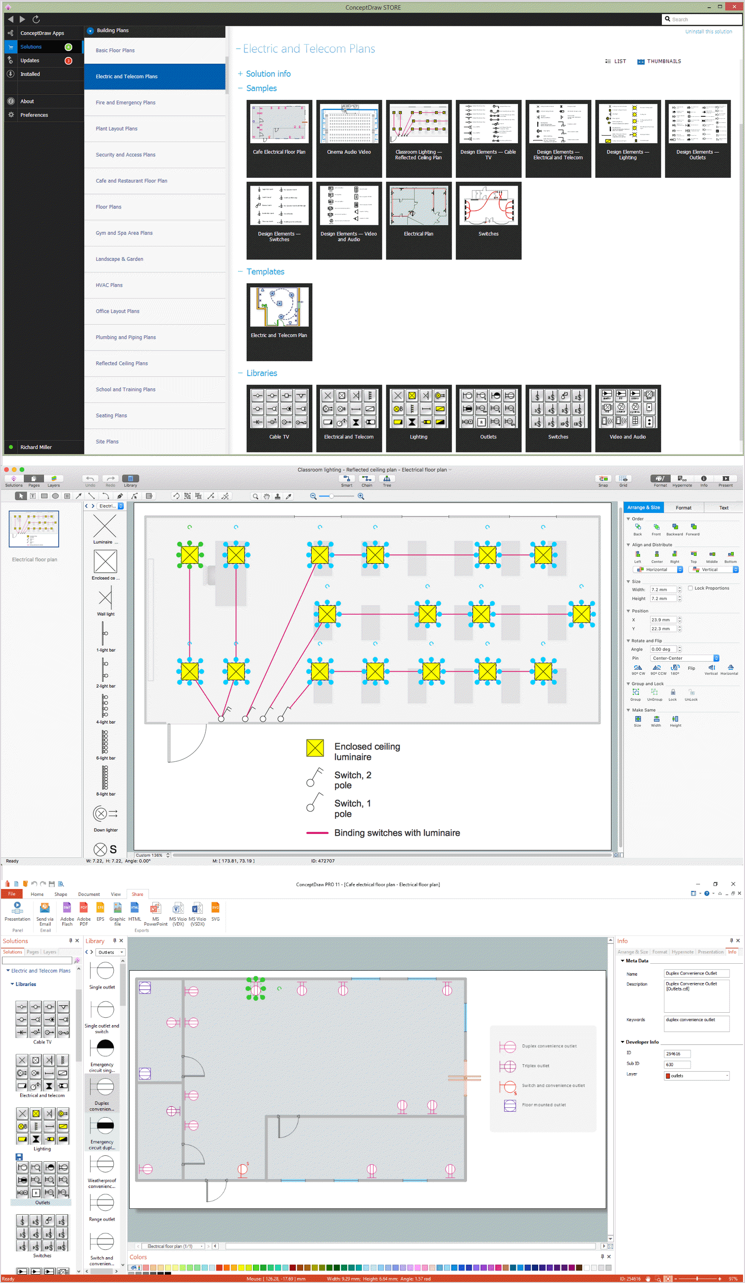
The vector stencils library Shipping and Receiving contains shapes of equipment for ConceptDraw DIAGRAM diagramming and vector drawing software.
Use it to draw plant interior design floor plans, factory warehouse equipment layout plans, floor plans of shipping and receiving centers with equipment for hauling, transporting, and distributing manufactured goods, freight, cargo, and stock from plants and industrial facilities.
This design elements library is included in Plant Layout Plans solution from Building Plans area of ConceptDraw Solution Park.
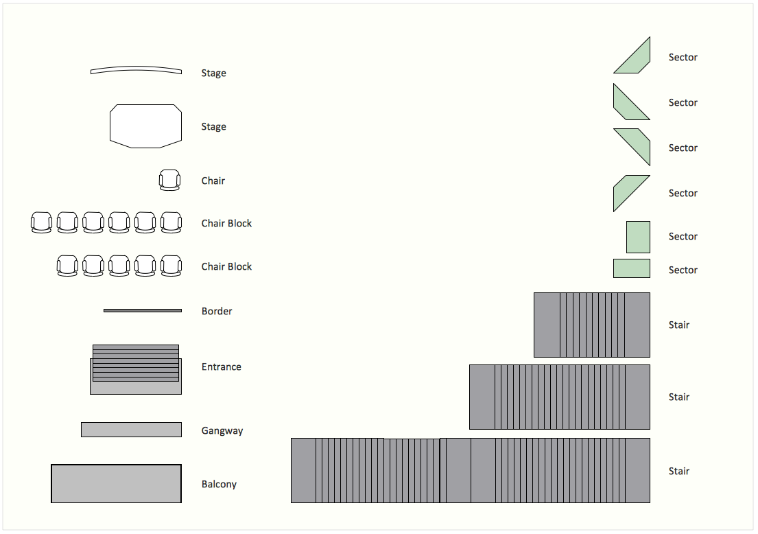
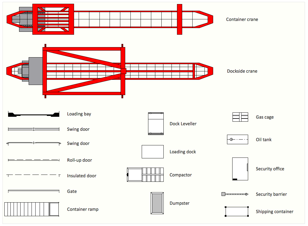
The Shipping and Receiving library contains 18 symbols:
- Loading bay
- Swing door 2
- Swing door 1
- Roll-up door
- Insulated door
- Gate
- Container ramp
- Dock leveller
- Loading dock
- Compactor
- Dumpster
- Gas cage
- Oil tank
- Security office
- Security barrier
- Shipping container
- Container crane
- Dock-side crane
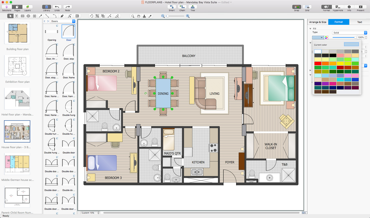
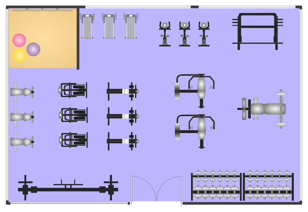
Sample 1. Interior Design Software. Design Elements — Shipping and Receiving
for macintosh and windows
Solution Building Plans from ConceptDraw Solution Park provides vector stencils libraries with design elements for drawing plant layout plans.
Use ConceptDraw DIAGRAM diagramming and vector drawing software enhanced with Building Plans solution to draw your own plant layouts for production, storage, distribution, transport, shipping and receiving of manufactured goods.
Read more about Home and Landscape design
NINE RELATED HOW TO's:
It’s not easy to plan all the details of your landscape at once. Therefore, you can use a bubble diagram to create a draft of the future project. You can develop any bubble diagrams and use them in your landscape design project with ConceptDraw DIAGRAM and it’s predesigned templates.
This bubble diagram can be applied while initiating the development of garden and landscape design. The bubble diagrams used for this purpose are different from the classic bubble diagrams. Being used in landscape and garden design, they obtain the quite another understanding. Bubbles in this diagram visualize some captured areas, which define the general spaces of a future garden: lawn, flower garden, pool, built-up area, lighting, etc. The bubble diagram represents the landscape project without any special expenses on its creation. It is better to make such simple sketch before you drill down into detailed project and cost estimates.
Picture: Bubble diagrams in Landscape Design with ConceptDraw DIAGRAM
How to create a Residential Electric Plan quick and easy? The simplest way is to use the tools of ConceptDraw DIAGRAM software extended with Electric and Telecom Plans Solution.
Picture: Residential Electric Plan
Related Solution:
ConceptDraw DIAGRAM extended with Floor Plans Solution from the Building Plans Area is a quick floor plan software for creating great-looking floor plans, floor charts and blueprints for facilities management, move management, office supply inventories, assets inventories, office space planning, and cubicles.
Picture: Floor Plan
Related Solution:
ConceptDraw DIAGRAM diagramming and vector drawing software extended with Floor Plans Solution from the Building Plans area of ConceptDraw Solution Park lets you the possibility to create Floor Plan of any complexity in minutes.
Picture: Create Floor Plan
Related Solution:
A database is a data collection, structured into some conceptual model. Two most common approaches of developing data models are UML diagrams and ER-model diagrams. There are several notations of entity-relationship diagram symbols and their meaning is slightly different. Crow’s Foot notation is quite descriptive and easy to understand, meanwhile, the Chen notation is great for conceptual modeling.
An entity relationship diagrams look very simple to a flowcharts. The main difference is the symbols provided by specific ERD notations. There are several models applied in entity-relationship diagrams: conceptual, logical and physical. Creating an entity relationship diagram requires using a specific notation. There are five main components of common ERD notations: Entities, Actions, Attributes, Cardinality and Connections. The two of notations most widely used for creating ERD are Chen notation and Crow foot notation. By the way, the Crow foot notation originates from the Chen notation - it is an adapted version of the Chen notation.
Picture: ERD Symbols and Meanings
Related Solution:
Triangle diagram example of DIKW pyramid has 4 levels: data, information, knowledge and wisdom.
Picture: Pyramid Diagram
Related Solutions:
ConceptDraw DIAGRAM diagramming and vector drawing software offers the Site Plans Solution from the Building Plans Area of ConceptDraw Solution Park for convenient drawing the site plan of any complexity.
Picture: Site Plan
Related Solution:
ConceptDraw DIAGRAM software extended with Electric and Telecom Plans Solution is the best software for drawing the Telecom Wireless Plan of any complexity.
Picture: Telecom Wireless Plan
Related Solution:
It would be possible to draw a plot plan on a piece of paper, but it is much more convenient, faster, and more accurate to do this using the professional software to design landscape ConceptDraw DIAGRAM. Even if you don't have the skills to work in graphic programs, you can easily create an attractive landscape design. Use the professional tools provided by Landscape & Garden solution from ConceptDraw Solution Park.
Picture: Software to Design Landscape
Related Solution: