Building Plans with ConceptDraw DIAGRAM
Have you decided to build a new house? Or you need to show a planning of an existing house to a potential customer? Probably you need to repair your house? For all these cases you will need the plan of the building.
As a matter of fact, the plan of a building consists of plans of all premises of the building, combined in one document. If the building has several levels or floors, so there can be dozens of such documents. On the building plan all premises of the building with indications of all dimensions (walls, windows, apertures of doors) are presented, also there indicated ventilating shafts and wells, stairs and technical premises.
Building plans are necessary for architects (actually, they are the result of their work), designers, builders, realtors and, surely, to any house owner. Besides, any office building has the plan of emergency evacuation which is also a plan of the building with indication of moving directions at evacuation.
If it is necessary for you to create the building plan you can draw it manually on the sheet of paper, but also you can use special software. With the help of ConceptDraw you can create the building plan of any difficulty. Thanks to special templates and objects libraries this won't take you much time and won't demand special skills.

Example 1. Building Plans Solution with ConceptDraw DIAGRAM
As ConceptDraw supports the work with multiple sheet documents, you can keep plans of all building floors in one document not depending on how many floors or levels there exist.

On each sheet your can use unlimited number of layers which is very convenient at creation of the plan of multilevel premises. Besides you can use layers for creation of premises plan with different degree of the detailed elaboration- for example, with furniture or without it. Also the usage of layers is very convenient at the necessity of study of projection of building floors.


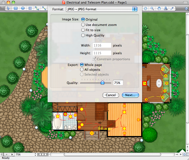
Ready building plan can be printed, saved in one of the formats supported by ConceptDraw or send by e-mail to colleagues or clients. Also you can upload ready building plans on your website as the catalogue of proposals.
TEN RELATED HOW TO's:
You need design the Classroom Layout for the school, high-school, university? Now it's incredibly easy to do this in ConceptDraw DIAGRAM software which was supplied with School and Training Plans Solution from the Building Plans Area.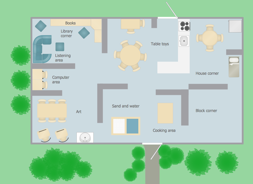
Picture: Classroom Layout
Related Solution:
Building plans are usually very complicated and a hard work to do. It would be nice to use a proper drawing software to facilitate the task. Design a site plan quick and easily with all the stencils and samples from ConceptDraw libraries.
This drawing shows content of the ConceptDraw vector libraries related to the site planning and arrangement of the living environment. ConceptDraw delivers about 50 libraries containing near one and a half thousands vector objects that will help you to design territory arrangement plans and make the Site plan sketches. You can use the Parking and Roads library for designing a parking space, or drawing transport management schemes. The Site Accessories library provides a number of objects, that allow you to depict various equipment of vehicle access control, street lamps, benches, trash cans and other items of the street environment.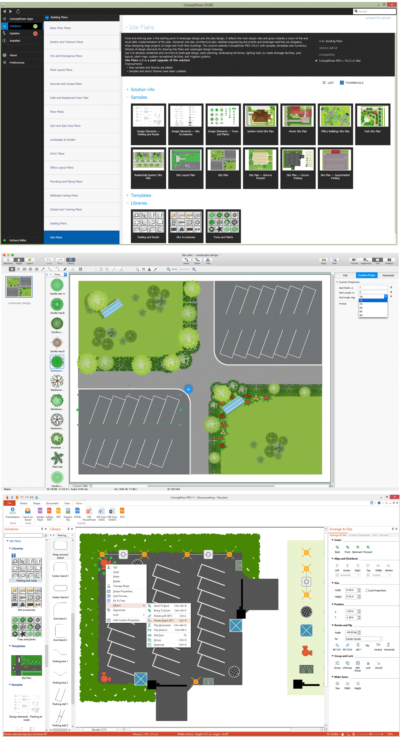
Picture: Building Drawing Software for Design Site Plan
Related Solution:
Sometimes, it's not easy to fit everything you need into your premise. So, you can discover how to use building plan examples and get inspired from viewing them. You can find a lot of office layout and floor plans templates in the ConceptDraw Solution Park.
This drawing shows the sample of interior design of a middle-size restaurant. It was designed with a help of ConceptDraw Cafe and Restaurant Plans solution. Extensive libraries of vector objects of the interior element enabled us to design this example quickly and with no efforts. You can use this interior plan as a template while designing an interior for your own restaurant. It will help you to compose and organize elements of the interior, to bring a balance between free space and furniture in your establishment. It can be applied to organize and arrange the furniture, equipment and decorative elements in the restaurant interior and achieve balance between furniture and free space.
Picture: How To use Building Plan Examples
Related Solution:
When deciding to start your own business, you have to take into account a bunch of different aspects. One of the ways to get inspired is to look through various restaurant floor plans samples or interior photos of already known establishments. This will help you, but keep in mind that a really unforgettable establishment must be unique.
This restaurant floor plan diagram was designed using ConceptDraw Cafe and Restaurant Floor Plan solution. It can be used as a sample while considering a custom restaurant design. With the help of this example you can estimate the amount of furniture best for a dining room or kitchen of the restaurant. In addition, this plan would be useful as a check list when you will consider a list of the furniture and equipment needed for all areas of the future restaurant.
Picture: Restaurant Floor Plans Samples
Related Solution:
Cafes and restaurants are the places for relax and recreation, so the most important is their design and atmosphere of comfort, harmony, and uniqueness. So Cafe Design requires great creativity and efforts from the designers. ConceptDraw DIAGRAM software extended with Cafe and Restaurant Floor Plan solution from the Building Plans area of ConceptDraw Solution Park is the most simple way of displaying your Cafe Design ideas and plans first on the computer screen, and then on the paper.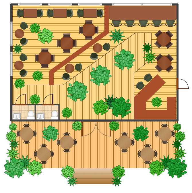
Picture: Cafe Design
Related Solution:
Public catering business will always be in demand.To attract a lot of clients, it’s important to have a detailed banquet hall plan, a diverse menu and reasonable prices. If you want to create a good plan, you can use drawing software.
When planning and considering the layout of a banquet hall, one must take into consideration, that it is very significant to make it stylish with correctly selected appointment and celebratory belongings. Tables and seating must be handily arranged. The furniture arrangement can changes depending on client requirements, kind of banquet and amount of guests. ConceptDraw Cafe and Restaurant Plans solution supplies a dozens of predesigned vector graphic objects of banquet furniture and accessories. Thus you can design the Banquet Hall layout for the celebrations in any style and any number of guests.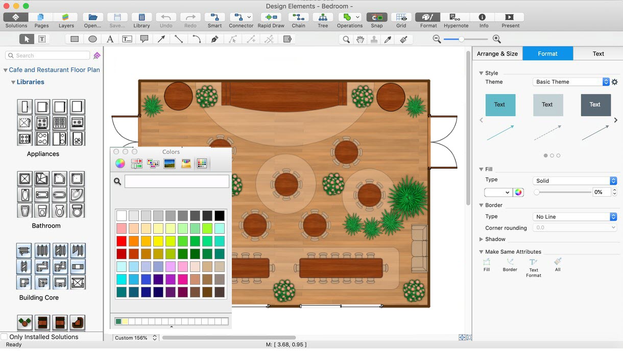
Picture: Banquet Hall Plan Software
Related Solution:
Some organization hold offices for years and decades, or even build their own campuses. However, if it’s time for your organization to move to another building, drawing software for designing office layout plan would come in handy. With such software you can save a lot of time and create a new layout or try to save old layout in a new building.
This office layout plan is an example of a typical office furniture and equipment arrangement. This drawing provides a graphic view of the office area and its facilities including furniture and office equipment. It can be used as template which represent, desks, files, and other pieces of equipment that can be re-arranged according the certain requirements to office space and facilities. The vector graphic objects that represent various office layout elements such as special office furniture and equipment can help you to shape a number of creative ideas and develop your office layout plan.
Picture: Building Drawing Software for Design Office Layout Plan
Related Solution:
How to draw Metro Map style infographics of New York subway.
New York Subway has a long history starting on October 27, 1904. Since the opening many agencies have provided schemes of the subway system. At present time are 34 lines in use. This page present New York City subway map construct with Metro Map Solution in Conceptdraw DIAGRAM software. This is a one-click tool to add stations to the map. It lets you control the direction in which you create new stations, change lengths, and add text labels and icons. It contains Lines, Stations, and Landmarks objects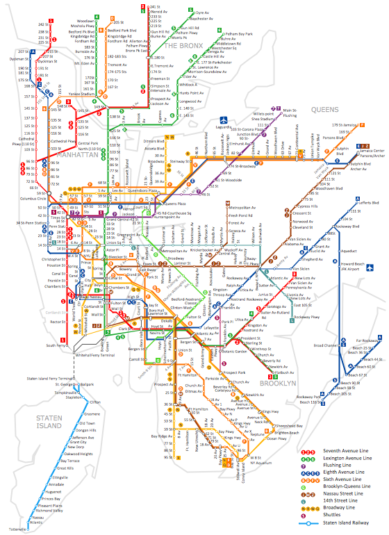
Picture: How to draw Metro Map style infographics? (New York)
Related Solution:
Nova Scotia is one of Canada's three Maritime provinces and constitutes one of the four Atlantic Canada provinces.
The vector stencils library Nova Scotia contains contours for ConceptDraw DIAGRAM diagramming and vector drawing software. This library is contained in the Continent Maps solution from Maps area of ConceptDraw Solution Park.
Picture: Geo Map - Canada - Nova Scotia
Related Solution:
A layout is a way that furniture is arranged in some place. It’s not difficult to develop a store layout using software with tons of templates and libraries with vector shapes of furniture, doors, walls etc. Create a plan in five minutes and have more time to implement it.
Designing the floor plan for a new store is very important step for a small business. Well thought out and well-done floor plan is the foundation of the store layout. It should provide a basis through which to make out and organize everything else. Sometimes a small stores have a small floor space, so well thought out arrangement of furniture and commercial equipment is crucial to the success of the business. By using the ConceptDraw Floor Plans solution you can make a floor plan for your store quickly and effortlessly.
Picture: Store Layout Software
Related Solution: