Living Room. Piano in plan
This template was created in ConceptDraw DIAGRAM diagramming and vector drawing software using the Floor Plans Solution from the Building Plans area of ConceptDraw Solution Park.
On this template you can see the plan of the Living Room. Living room is a main place of the house, flat. It is very important that it was light, comfortable, harmonious, cosy and functional.

Pic 1. Floor plan solution
Living room is the place where all family comes together, where receive guests. The interior of the living room complements the piano which helps to create a warm atmosphere. The piano is not just a musical instrument, in the room interior it becomes the most noticeable detail. The piano always organically entered in any interior.
Best Interior Design Software for macOS&Windows ConceptDraw DIAGRAM allows you design the interior of your dreams quick and easy.
Floor Plans Solution from the Building Plans area of ConceptDraw Solution Park contains 15 libraries with large quantity of ready-to-use vector objects such as various furniture, interior items, including piano, flowers, etc. It also provides many templates and samples to help you in your interior designing.

Pic 2. Living Room. Piano in plan
Use the predesigned vector objects, templates and samples to create your own plan of the living room in a few minutes.
The Floor Plans created with ConceptDraw DIAGRAM are vector graphic documents and are available for reviewing, modifying, and converting to a variety of formats (image, HTML, PDF file, MS PowerPoint Presentation, Adobe Flash or MS Visio).
Read more about Home and Landscape design
NINE RELATED HOW TO's:
It’s very important for any establishment to have a fire exit plan and to train it several times a year. The plan must be put on each floor of the building in a way that it could be easily seen. To make the plan clear and descriptive, you should look through examples and then create one for you your building.
Find out the fire exit plan example created with ConceptDraw DIAGRAM and its Fire and Emergency Plans solution. This plan is a floor plan that shows the ways in which people inside the building can be evacuated in the event of a fire. The location of telephones, fire extinguishers and first aid kits are indicated on the fire exit plan. The Legend in the lower right corner of the plan makes it clear and easy-to-read. Such plan should be placed on the wall on each floor of the building.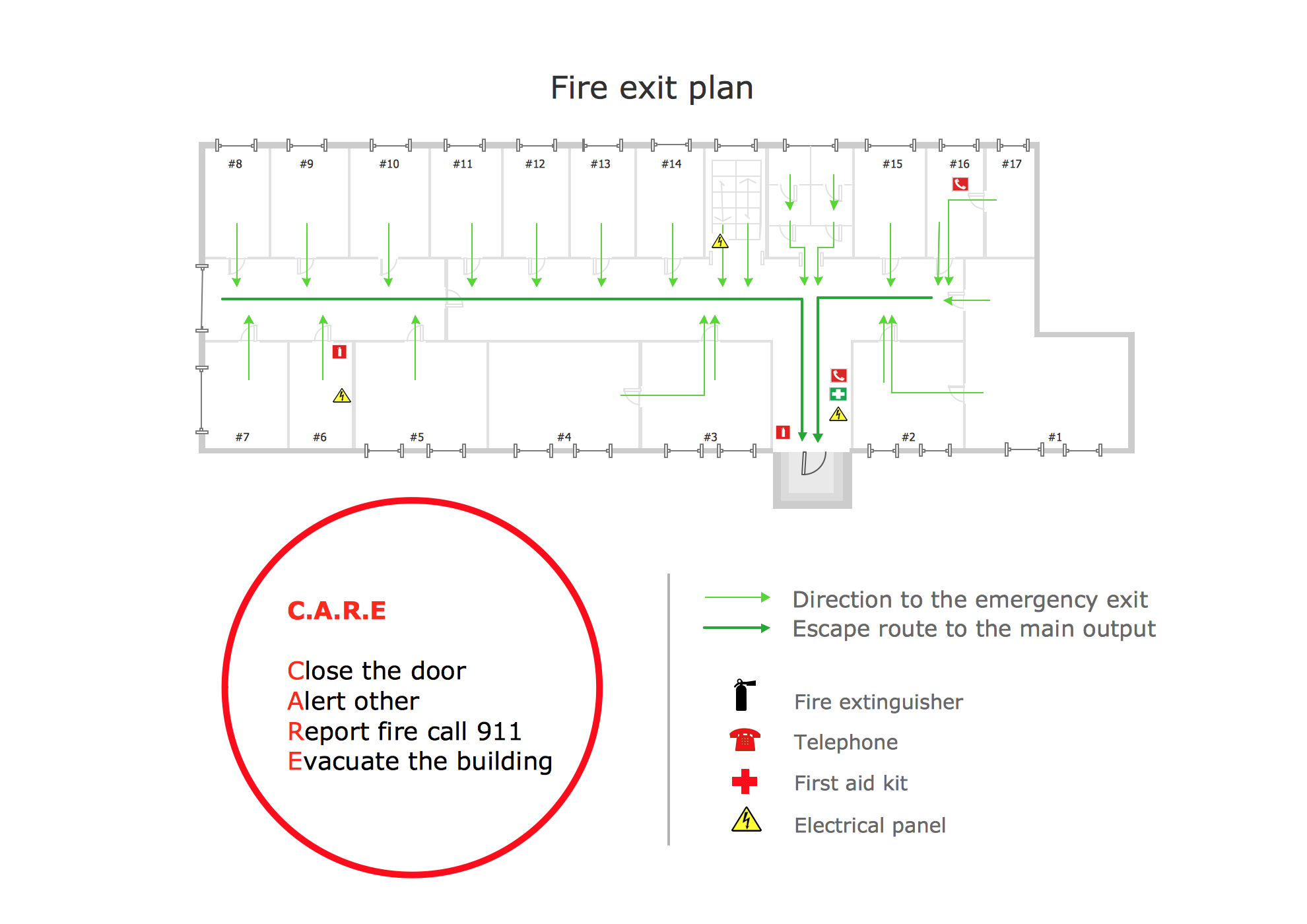
Picture: Fire Exit Plan. Building Plan Examples
Related Solution:
ConceptDraw DIAGRAM extended with Workflow Diagrams solution from the Business Processes area is a powerful workflow diagram software which offers you a variety of workflow examples.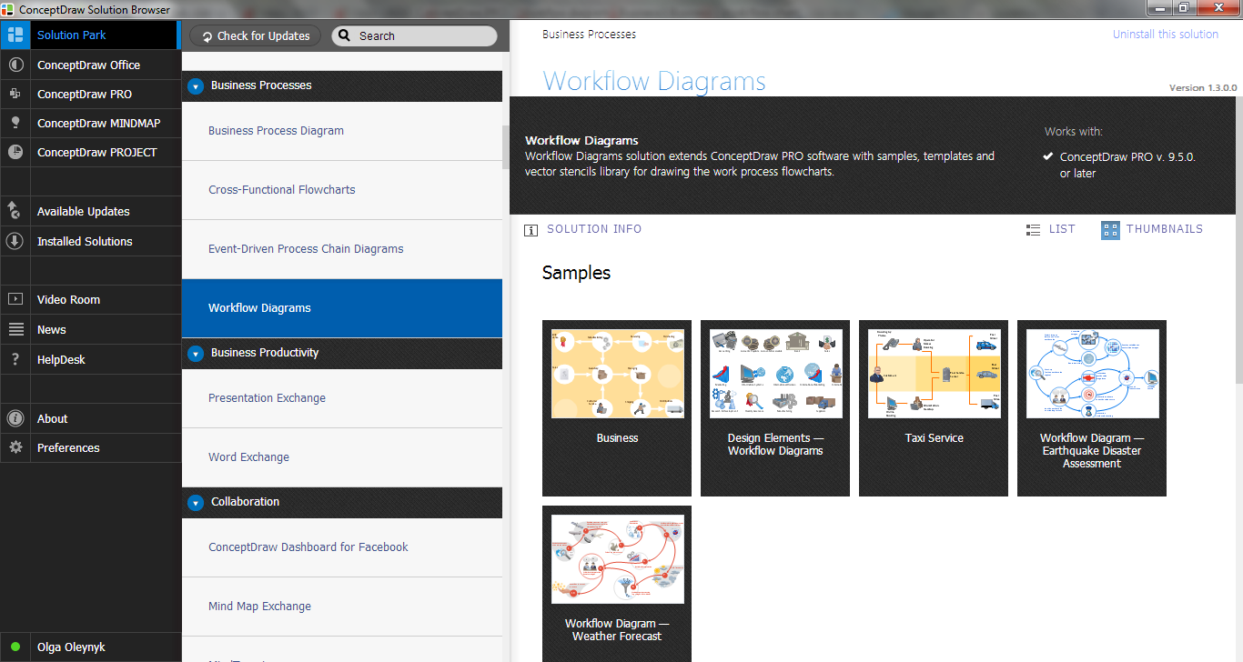
Picture: Workflow Examples
Related Solution:
Cabinet is a necessary room in the house. It is very important that the cabinet was comfortable and convenient with elaborated design that dispose to the maximize productive work. The cabinet design is a reflection of the personality, habits and character traits of its owner.
Floor Plans Solution provides templates, samples and wide collection of pre-designed vector stencils that allow you to create the cabinet design plans of any complexity quick, easy and effective.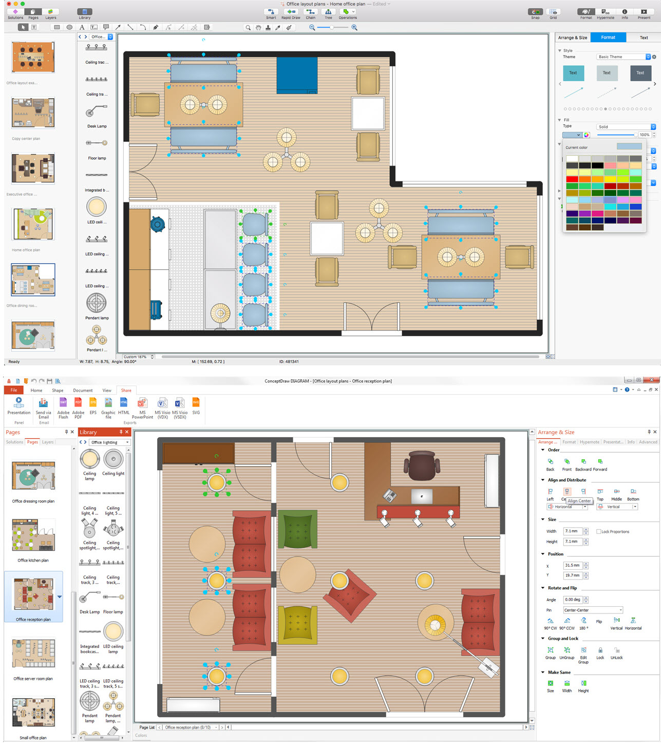
Picture: Cabinet Design Software
Related Solution:
ConceptDraw DIAGRAM is a powerful diagramming and vector drawing software. Extended with Floor Plans Solution from the Building Plans area, ConceptDraw DIAGRAM became the ideal software to help you create a Floor Plan for any premise quick and easy.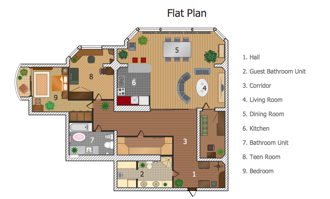
Picture: Create a Floor Plan
Related Solution:
This sample shows diagram of the electrical wiring of the apartment. You can see the arrangement of the sockets and the main control on this diagram. The electrical diagram is the important part of the architectural project.
Using the predesigned objects, templates and samples of the Electrical Engineering solution for ConceptDraw DIAGRAM you can create your own professional electrical diagrams, wiring diagrams quick and easy.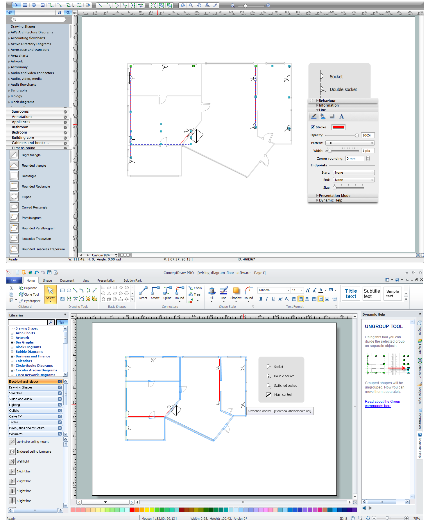
Picture: Wiring Diagram Floor Software
Related Solution:
ConceptDraw DIAGRAM software extended with Reflected Ceiling Plans Solution from the Building Plans Area is a perfect software for drawing Reflected Ceiling Plan of any complexity.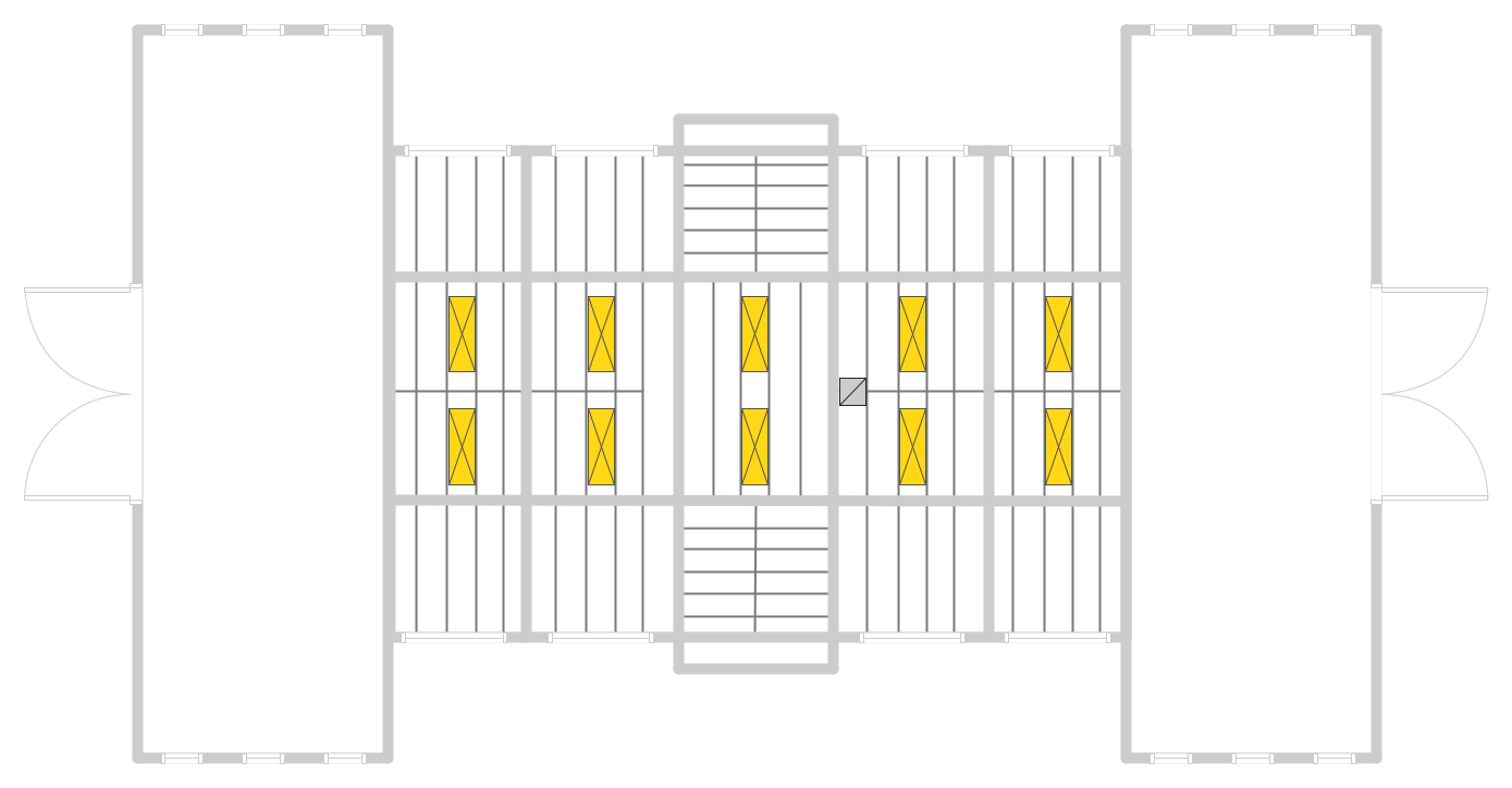
Picture: Reflected Ceiling Plan
Related Solution:
House of Quality Matrix Software - Use the predesigned objects from the Involvement Matrix Objects Library from the Seven Management and Planning Tools Solution to create professional looking House of Quality Matrices in minutes.
Picture: House of Quality Matrix Software
Related Solution:
Communication via Internet nowadays is almost irreplaceable part of lifestyle. It’s needless to say that providing that communication is not a piece of cake, and network diagram software is useful for representing all the interconnections between network devices. These diagrams are also helpful for educational purposes.
This drawing depicts the network topology of the sample web studio. This is a physical type of network diagram. It is depicting the network, end-user equipment and connections between them. The given network has combined the both star and mesh network topology features. This diagram is a tool of network administrator. it delivers the actual information on location of servers, hubs, switches, routers, and other telecommunication equipment. The collection of network related symbols provided with ConceptDraw Network Diagrams solution represents the entire network components. All Symbols are standard. Therefore, network specialists can effortlessly decrypt this diagram.
Picture: Network Diagram Software
Related Solution:
ConceptDraw DIAGRAM diagramming and vector drawing software extended with Floor Plans Solution from the Building Plans area of ConceptDraw Solution Park lets you the possibility to create Floor Plan of any complexity in minutes.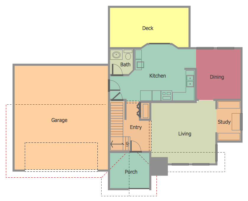
Picture: Create Floor Plan
Related Solution: