Fire Exit Plan. Building Plan Examples
Fire and emergency exit plans
An “emergency exit” in a building is a special exit for emergencies such as a fire. The the combined use of the regular as well as the special exits allows fast evacuation. It also provides an alternative if the route to the regular exit is blocked by fire or in case of other circumstances. Fire exits are usually strategically located (e.g. in a stairwell, hallway or other places) outward opening door with an exit signs on as well as a “crash bar”. The name is a reference to when they are frequently used. A fire exit can also be a main doorway “in” or “out”. A “fire exit” can be also called a “fire escape” and it is another special kind of emergency exit, which is usually mounted to the outside of a building. Following the events in 1883 in England when more than 180 children died because of a door being bolted at the bottom of a stairwell, the government of the United Kingdom of the Great Britain began legal moves towards enforcing the minimum standards for the building safety. These processes slowly led to the legal requirement insisting in the venues having a minimum number of outward opening emergency exits as well as locks, which could be easily opened from the inside of the building.
These moves mentioned above were not globally copied for some time as in the United States of America in 1911 146 factory workers died in the fire at the factory when they were stopped by locked exits. Also 492 people died in the fire in a Boston nightclub in 1942, which led to the regulations requiring that exits of large buildings open outward and that enough emergency exits should be provided for accommodating the building's capacity.
Society all over the globe ended up demanding alterations in emergency regulations after suchlike disasters including the nightclub fire in Argentina in 2004. Thus the investigation was launched by the Argentine federal government straight after 194 people were killed in that fire. The reason for those emergency exits being shut was that the owners wanted to stop people from sneaking into the nightclub without paying.
Local building codes often dictate the number of fire exits required for a building of a given size, which may include specifying even the number of the stairs. For any construction bigger than a domestic building, modern codes inevitably specify at least two sets of stairs, but such stairs must be completely separate from each other. Some architects meet the requirement of providing two stairs in a way when these two stair openings occupy the same floor space, intertwined. It may seem to make no functional sense to have two stairs so close to each other, but exactly this regulation meets the requirements of the building codes.
Knowing where the emergency exits are in buildings can simply save your life and providing other people with this information can save their lives. Some buildings, such as schools, have fire drills for practicing using the emergency exits. Many lives could have been saved and many disasters – prevented, if people had known where the fire escapes were. That is why having the emergency exit plans is so important nowadays. These exits should have never been blocked as there were on 11.09.2001 in the World Trade Centre when some of the emergency exits inside the building were inaccessible and some of the others were simply locked. In the hospital in Moscow in 2006 the emergency exits were locked and most of the windows barred shut, so many people were killed.
In many countries, it is strictly required that all new commercial buildings include well-marked emergency exits. The older buildings must be retrofitted with the “fire escaped” and in the countries where emergency exits are not standard, fires will often result in a much greater loss of life. Some of the skyscrapers have stairwells with the standard emergency exit signs on each of the doors which then lock upon closing and so users of these stairwells can be trapped: in tragic cases they may know or may not that the only door that opens from the inside is the one on the ground floor.
Another problem which is becoming a very serious one as well as very common in the United States of America since 2005 is that the retail stores at night close one of their main exits through the makeshift heavy metal barriers and other things right in front of these exits, which actually lock their exits completely. A huge scope of mechanical exit systems has also been equipped with plates saying something like "Do not use this exit" or warning users that a heavy penalty will be assessed for non-emergency use which can confuse those who need to escape. Some of the systems do not allow the exit to be opened until its user signals the intention of using the exit way out using some special button for a while, such as for twenty seconds, for example. It is also common for these exits to remain completely locked until somebody tests them so they had better get tested in advance to make sure that people can easily use them when needed not having troubles with such a simple task.
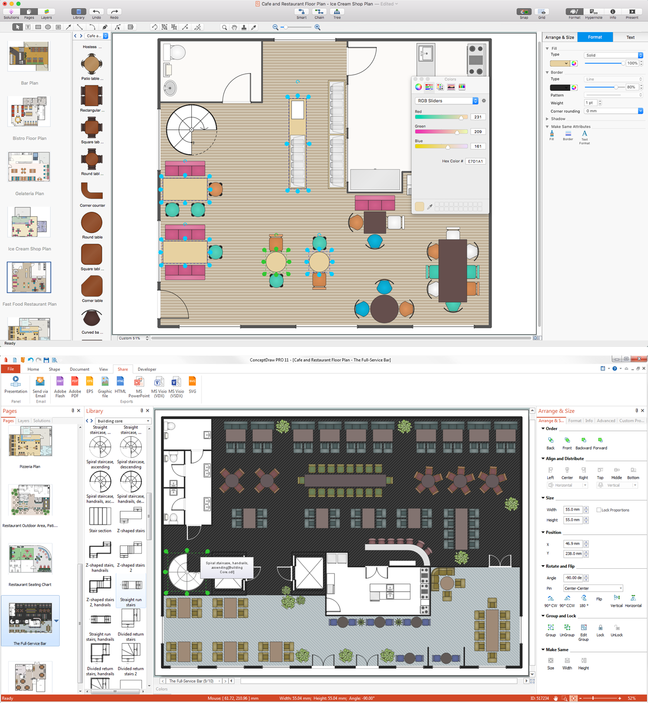
In order to make it safe both for you and for your employees as well as your clients who come to pay you a visit time to time and who can get trapped in a building, especially if your office is in a high building on one of the top floors of it, then you must make the fire exit plan in case of fire enabling people to live the building on time avoiding being hurt, injured or even dead. For making such plan you can always use ConceptDraw DIAGRAM software which is one of the best drawing applications providing all of the necessary tools for making your own plans, including the fire exit ones.
Using the appropriate Solution which can be found and downloaded from the “Building Plans area” of ConceptDraw Solution Park, which provides examples, templates and vector stencils library, is always beneficial while working in ConceptDraw DIAGRAM diagramming and vector drawing software. Use it today for designing your own convenient in use and simple fire and emergency plans and schemes, such as Evacuation plans, Home Emergency plans, Office Emergency plans, Fire safety diagrams, Fire Exit plans, Fire Emergency plans, Fire Evacuation plans and Business Emergency plans.
Solution from Building Plans area of ConceptDraw Solution Park provides examples, templates and vector stencils library for ConceptDraw DIAGRAM diagramming and vector drawing software.
Use it to design differend types of fire and emergency plans and schemes:
- Evacuation plans
- Home Emergency plans
- Office Emergency plans
- Fire safety diagrams
- Fire Exit plans
- Fire Emergency plans
- Fire Evacuation plans
- Business Emergency plans
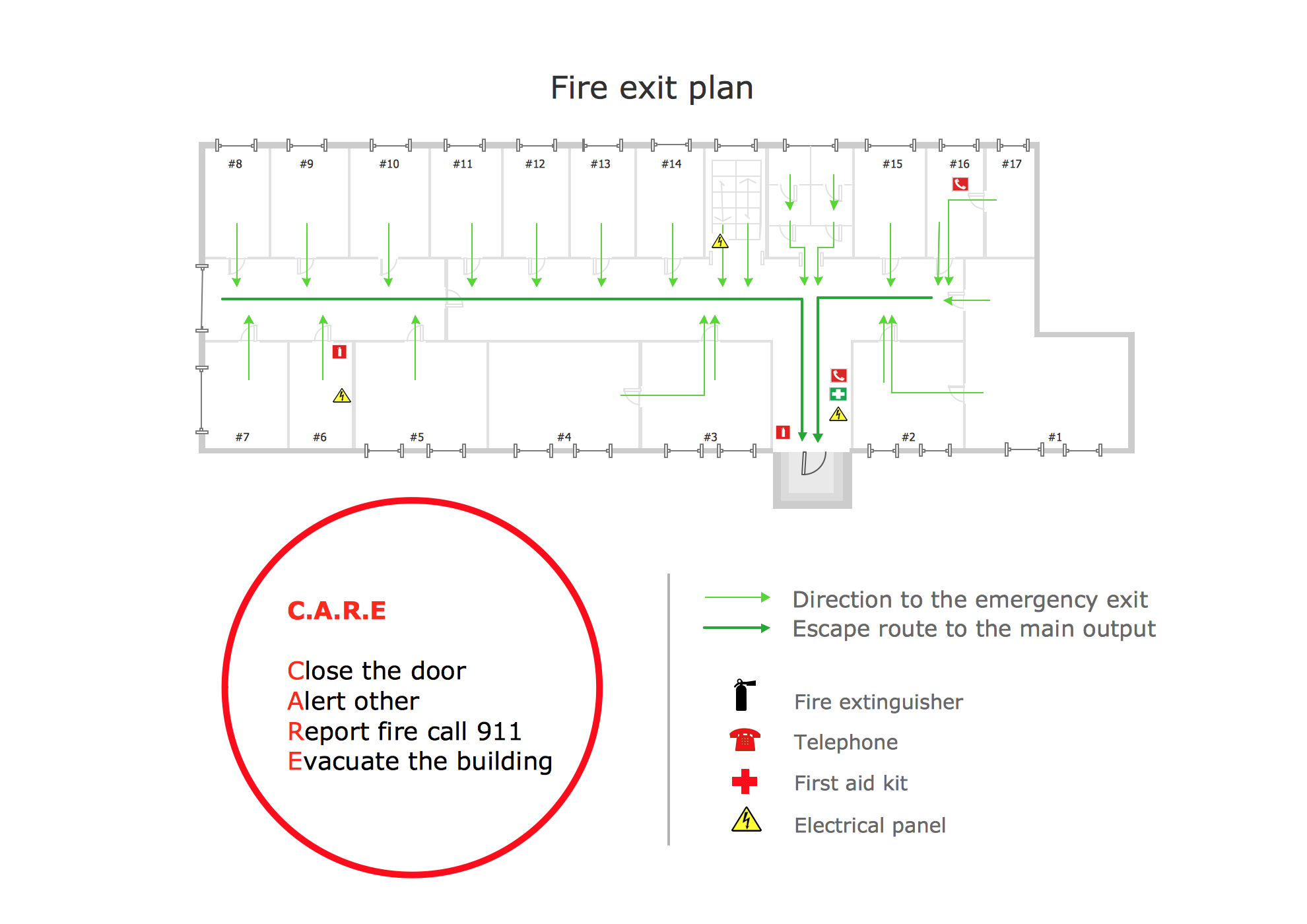
Sample 1. Office Fire Exit Plan
Fire exit plan is used in hospitals, hotels, business centers, metro, airports, schools, etc. This sample is drawn using ConceptDraw diagramming and vector drawing software enhanced with Building Plans solution from ConceptDraw Solution Park.
Solution Building Plans from ConceptDraw Solution Park provides vector stencils libraries with design elements for drawing fire exit plans.
_Win_Mac.png)