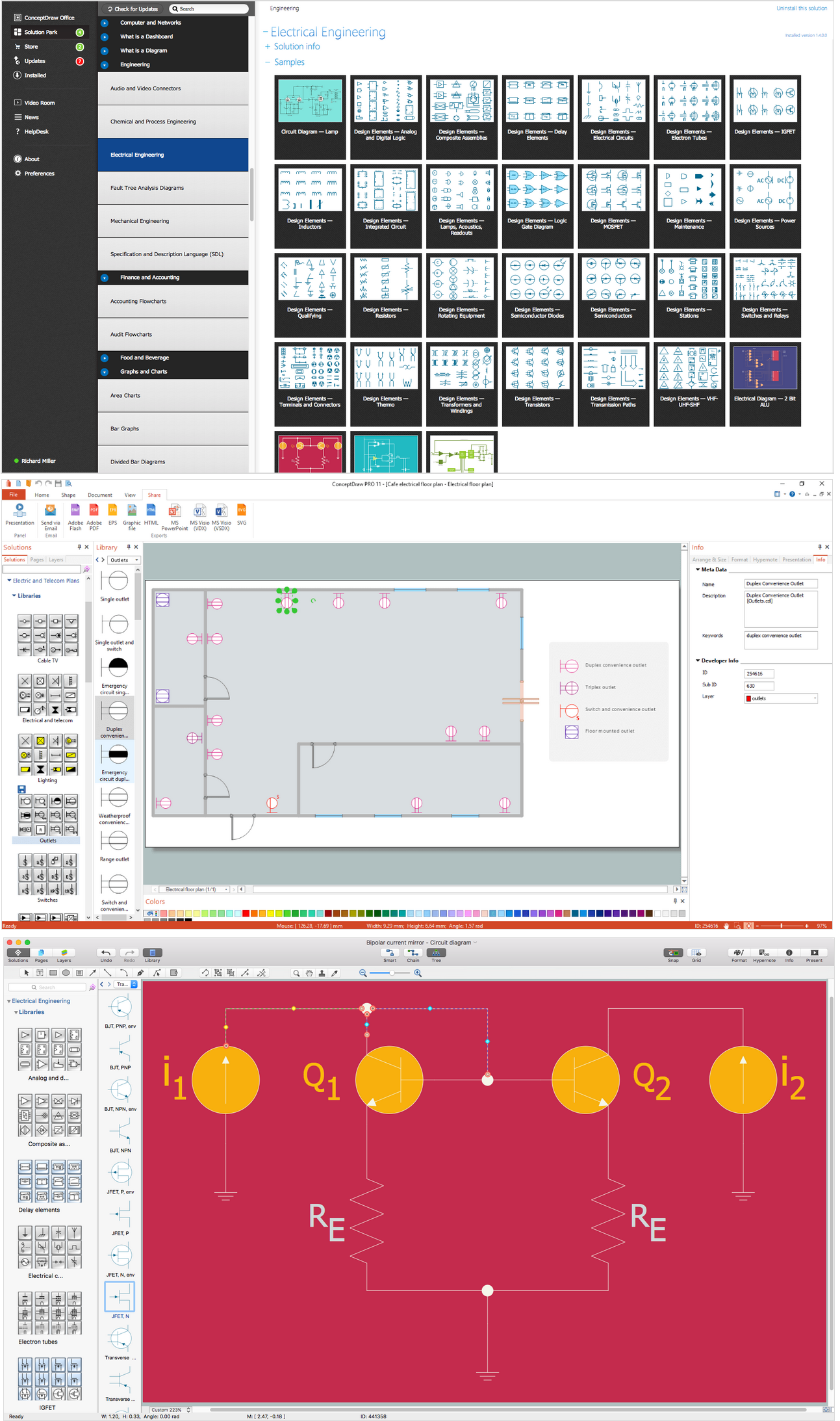
Pic. 1. Wiring Diagram with ConceptDraw DIAGRAM
A circuit diagram makes use of standardized symbols that represent electrical components or devices. It is easier to draw these symbols than drawing the concrete pictures of the components.
The graphics elements found in the Electrical Engineering solution can help you design electrical schematics, circuit and wiring blueprints, power systems diagrams, and maintenance and repair diagrams.
26 libraries, 926 electrical schematic symbols from electrical engineering.

Analog and Digital Logic symbols

Electrical and Telecom Symbols

Delay Elements symbols

Electrical Circuits symbols

Electron Tubes symbols

IGFET symbols

MOSFET symbols

Maintenance symbols

Lamps Acoustics Readouts symbols

Logic Gate Diagram symbols

Integrated Circuit symbols

Inductors symbols
The actual components might change appearance as the electronics industry revises them or renders them obsolete. The diagrams describe the way in which the components are connected electrically. There are drawn lines that stand for wires or conductors between the appropriate connection points on the symbols; no particular type of wire or physical distance between components is implied; two components might be separated by a few inches or centimeters or a meter or feet.
Pic. 2. Wiring Diagram
The graphics elements found in the Electrical Engineering solution can help you design electrical schematics, circuit and wiring blueprints, power systems diagrams, and maintenance and repair diagrams.
Using ConceptDraw DIAGRAM professional software for making wiring diagrams.
ConceptDraw DIAGRAM intended for creating wide variety range of wiring diagrams. These applications described in Industrial Engineering Area of ConceptDraw Solution Park.
House Electrical Diagram or House Wiring Diagram. It shows electrical circuits or put wires on the floor plan or house or building - let you create wiring diagram on a floor plan. The software features making a diagrams of weak-current installations, light-current systems and power circuits. All the tools for making wiring diagrams: graphical symbols collected in electrical stencils and located in ConceptDraw Solution Park, Design Elements of Electrical Engineering solution.
TEN RELATED HOW TO's:
A database is a data collection, structured into some conceptual model. Two most common approaches of developing data models are UML diagrams and ER-model diagrams. There are several notations of entity-relationship diagram symbols and their meaning is slightly different. Crow’s Foot notation is quite descriptive and easy to understand, meanwhile, the Chen notation is great for conceptual modeling.
An entity relationship diagrams look very simple to a flowcharts. The main difference is the symbols provided by specific ERD notations. There are several models applied in entity-relationship diagrams: conceptual, logical and physical. Creating an entity relationship diagram requires using a specific notation. There are five main components of common ERD notations: Entities, Actions, Attributes, Cardinality and Connections. The two of notations most widely used for creating ERD are Chen notation and Crow foot notation. By the way, the Crow foot notation originates from the Chen notation - it is an adapted version of the Chen notation.
Picture: ERD Symbols and Meanings
Related Solution:
ConceptDraw DIAGRAM is a powerful diagramming and vector drawing software. Extended with Chemical and Process Engineering Solution from the Industrial Engineering Area of ConceptDraw Solution Park, it became the best Chemical Engineering software.
Picture: Chemical Engineering
Related Solution:
What Is a Circle Spoke Diagram? It is a diagram which has a central item surrounded by other items in a circle. The Circle Spoke Diagrams are often used to show the features or components of the central item in marketing and management documents and presentations. ConceptDraw DIAGRAM extended with Business Diagrams Solution from the Management Area is the best software for creating Circle-Spoke Diagrams.
Picture: What Is a Circle Spoke Diagram
Related Solution:
Working as a designer, you might find developing projects exciting and difficult at the same time. It is a challenging task to create a usable interior design that will fulfill all the customer’s requirements. So, in order to aid yourself, you can use special software to create site plans, landscape designs, furniture layouts.
This example of an interior plan introduces an internal area of a small cafe. The floor plan demonstrates interior angle "view from above". It involves many different elements of furniture such as tables , chairs and various cushioned furniture. Also it includes a kitchen fixtures and furniture. Making this plan was managed by the ConceptDraw Cafe and Restaurant Floor Plan solution. The libraries, composing this solution contain about vector graphic 300 objects. It can be use to help interior designers to develop interior design proposals, communicate ideas and concepts that relate to a interior design.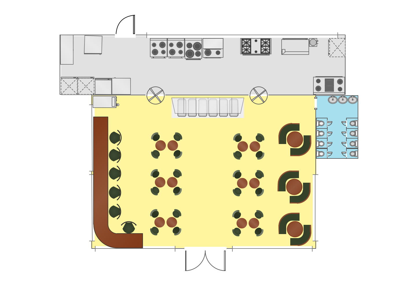
Picture: Interior Design
Related Solution:
There are several types of insulated gate field-effect transistors (IGFETs) in common use.
The early term metal oxide semiconductor field-effect transistor (MOSFET) is still in
use, and MOSFET is usually acceptable as a generic term for IGFETs. The metal oxide, and the insulation in the IGFET, is the insulating material between the gate terminal and the substrate between the source and drain terminals. This insulator must have very low leakage, of course, but another requirement for good performance of the transistor is that the dielectric constant of the material must be very high.
26 libraries of the Electrical Engineering Solution of ConceptDraw DIAGRAM make your electrical diagramming simple, efficient, and effective. You can simply and quickly drop the ready-to-use objects from libraries into your document to create the electrical diagram.
Picture: Electrical Symbols — IGFET
Related Solution:
Variable delay elements are often used to manipulate the rising or falling edges of the clock or any other signal in integrated circuits. Delay elements are also used in delay locked loops and in defining a time reference for the movement of data within those systems.
26 libraries of the Electrical Engineering Solution of ConceptDraw DIAGRAM make your electrical diagramming simple, efficient, and effective. You can simply and quickly drop the ready-to-use objects from libraries into your document to create the electrical diagram.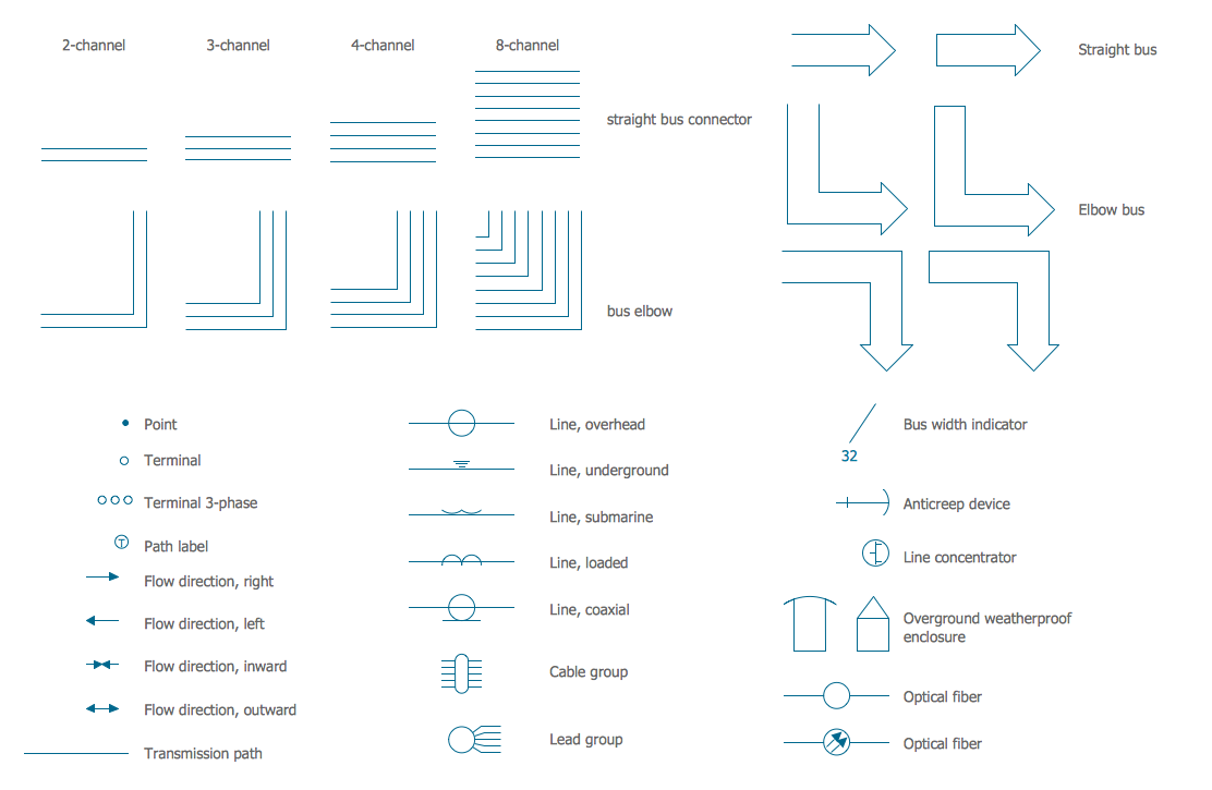
Picture: Electrical Symbols — Transmission Paths
Related Solution:
26 libraries of the Electrical Engineering Solution of ConceptDraw DIAGRAM make your electrical diagramming simple, efficient, and effective.
Picture: Electrical Symbols — Thermo
Related Solution:
Use Case Diagram Taxi Service UML. This sample was created in ConceptDraw DIAGRAM diagramming and vector drawing software using the UML Use Case Diagram library of the Rapid UML Solution from the Software Development area of ConceptDraw Solution Park.
This sample shows the work of the taxi service and is used by taxi stations, by airports, in the tourism field and delivery service.
Picture: UML Block Diagram
Related Solution:
Use ConceptDraw DIAGRAM software as powerful electrical engineering software and apply switches and relays electrical symbols in ✔️ electrical circuit diagrams, ✔️ electrical drawings, ✔️ electrical schematics, ✔️ wiring diagrams, ✔️ electrical blueprints
Picture: Electrical Symbols — Switches and Relays
Related Solution:
The Audio & Video Connectors solution contains a set of pre-designed objects, libraries, templates, and samples; allowing quick and easy diagramming of various configurations of audio and video devices.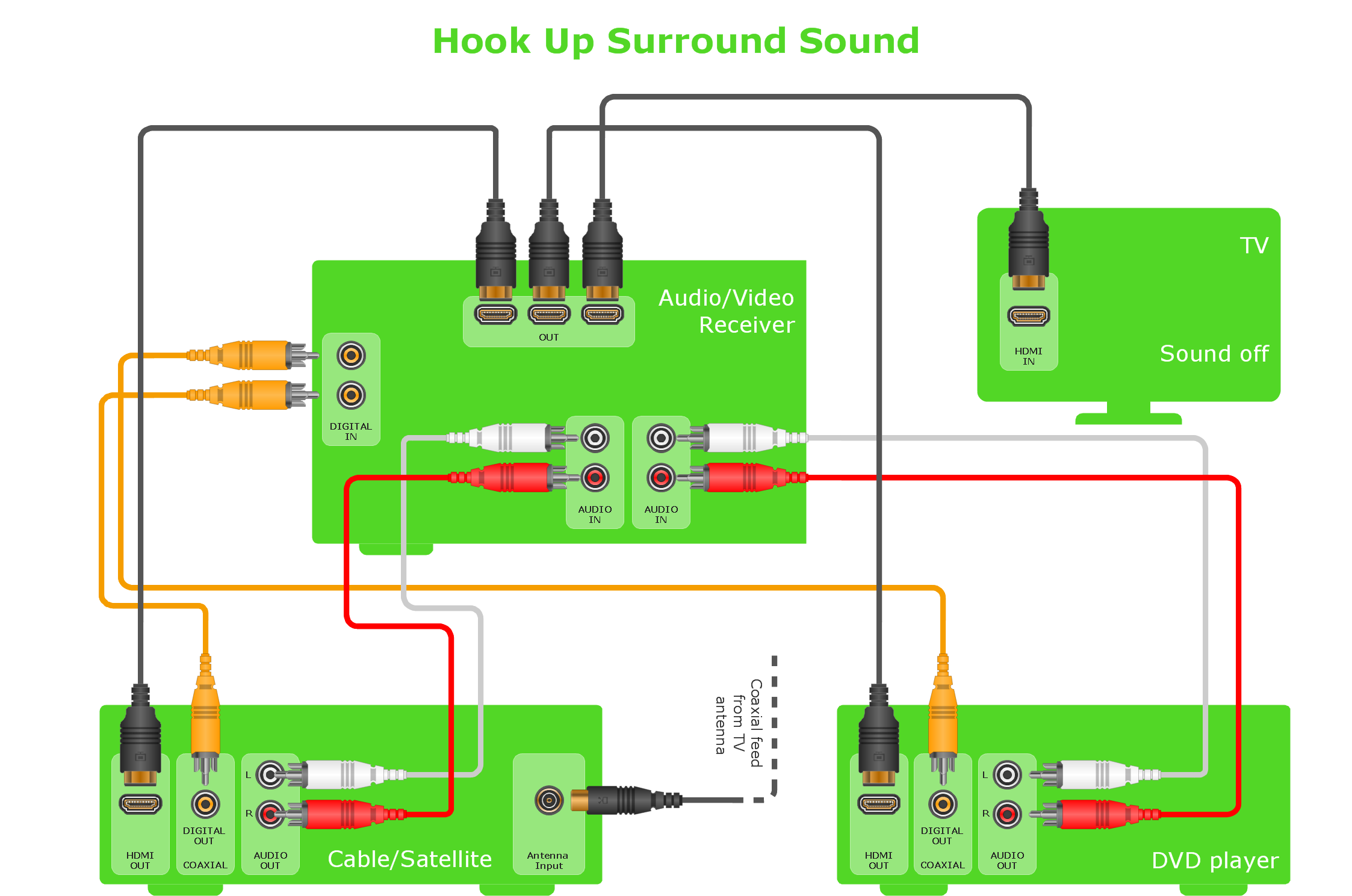
Picture: Audio and Video Interfaces and Connectors
Related Solution:
 Analog and Digital Logic symbols
 Electrical and Telecom Symbols
 Delay Elements symbols
 Electrical Circuits symbols
 Electron Tubes symbols
 IGFET symbols
 MOSFET symbols
 Maintenance symbols
 Lamps Acoustics Readouts symbols
 Logic Gate Diagram symbols
 Integrated Circuit symbols
 Inductors symbols
