Made with
ConceptDraw
DIAGRAM 18

Business process Flow Chart —
Event-Driven Process chain (EPC) diagrams

Event-Driven Process Chain (EPC)

A flowchart called “event-driven process chain” (also known as simply “EPC”) is used for modelling the business processes, configuring a so-called “enterprise resource planning” implementation as well as for improving the business processes. The usage for controlling the work share, including controlling the instances of the autonomous workflows, is possible in so-called “workflow management”, but they are not yet implemented.

The “event-driven process chain” method was developed by Mr. Scheer in the early 1990s for laying out the business process workflows. This method can be used by many different companies for the purpose of modelling, analyzing and redesigning any business processes going on within this business field of activity. Both events and functions mentioned in such “event-driven process chain” graph provide many different connectors, letting the business processes execute in an alternative and parallel way. There are no restrictions appearing to exist on the structures of EPCs, but non-trivial structures can involve parallelism and have ill-defined execution semantics. Once they are as we described, then they resemble “UML activity diagrams”.

There are many elements which are used in the “event-driven process chain diagrams”, which are “events” (passive elements that describe under what circumstances a function or a process works or which state a function or a process results in), “functions” (active elements that model the tasks or the activities within one company and also describe the transformations from an initial state to a resulting state), “Organization units” (determine which organization within the structure is responsible for which function), “logical connectors” (show the logical relationships between elements in the control flow) and many other.

There are in total three kinds of logical relationships, which are defined in event-driven process chains. One of these relationships is called “Branch and Merge”: it is used when there is a need to make a decision of which path to choose among a few control flows. A branch may have one control flow (which is usually incoming) as well as two or more so-called “outgoing” control flows. In case this condition is fulfilled, a branch activates only one of the “outgoing” control flows and it also deactivates the others. The counterpart of a branch is a “merge”, which may have two or more “incoming” flows and one “outgoing” control flow.

Another kind of relationships within a logical structure can be “Fork and Join” correspond which is meant to be used for activating all paths in the control flow. A “fork” may have only one incoming control flow as well as two or more outgoing control flows. Once the condition within “Fork and Join” correspond relationship is fulfilled, then a “fork” activates all of the “outgoing control flows” which go in parallel to each other. A join may have two or more “incoming control flows” as well as one “outgoing control flow”. In the “Event-driven Process Chain diagram” it never matters in what way the concurrency is achieved. A “fork” in the EPC is represented by an opening “AND” connectors and a “join” is represented as a closing “AND” connectors.

The third kind of relationships is “OR”, which corresponds for activating one or more paths among the control flows. An opening “OR” connector may have one “incoming control flow” and more than one “outgoing control flows”. Once the condition is fulfilled, an opening “OR” connector activates one or more control flows and it deactivates the rest of them. The counterpart to it is the closing “OR” connector. Once at least one of the “incoming control flows” is activated, then the closing “OR” connector will pass the control to the next element after it.

A “control flow” is another kind of relationships and it is used for connecting the events with functions, process paths or logical connectors creating a chronological sequence as well as logical interdependencies between them. A “control flow” is usually represented as a dashed arrow. “Information flows” though show the connection between functions as well as “input” or “output” of data. “Organization unit assignments” are the kind of relationship that shows the connection between an organization unit and the function it is responsible for.

The “Process paths” as a kind of relationship can be used as navigation aid within the event-driven process chain. These “Process paths” are there for showing the connection from (or to) other processes. This “process path” relationship is represented as a compound symbol, which is composed of a “function symbol” superimposed upon another so-called “event symbol”. In order to employ the “process path” symbol in an “event-driven process chain diagram”, a symbol has to be connected to the “process path” symbol, indicating the process being diagrammed incorporating the entirety of a second process. This second process is usually, for a purpose of a diagrammatic simplicity, is represented by a single symbol.

Event-Driven Process Chain (EPC)

Pic. 1. Event-Driven Process Chain (EPC)

You can create event-driven process chain diagrams with the help of many different applications, but the best tool is ConceptDraw DIAGRAM software extended with “EPC” Solution. Making “event-driven process chain diagram” with the aid of Data Flow Diagrams solution, which can be found in the Software Development area of ConceptDraw Solution Park on this site and so downloaded from as well as in ConceptDraw STORE, which is a new product of CS Odessa. ConceptDraw DIAGRAM application is always very simple in use and the process of creating such diagram will appear to be fun and entertaining as you will have all of the necessary tools for making great looking diagrams, such as templates and examples to simplify your work of drawing smart and professionally looking event-driven process chain diagrams.

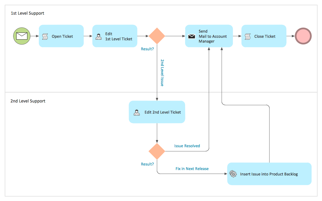
ConceptDraw DIAGRAM is a software for making business process flowcharts diagrams. The Event-driven Process Chain (EPC) Diagrams allows managers visually present business process models for making decisions for business.

The EPC is able to cope with extremely diverse and complex businesses processes. EPC diagram as a result can represent the various elements in a way which is easy to understand. A Process Flow Diagram tabulates process components' structure values in various real modes.

Business process Flow Chart — <br>Event-Driven Process chain (EPC) diagrams *

Pic. 2. Business process Flow Chart Tool — Event-Driven Process chain (EPC) diagram, Process flow diagram tool

Event-driven Process Chain Diagrams EPC solution contains also a set of different examples and templates. All EPC diagram samples and templates are available from ConceptDraw STORE, you can open them and change something as needed, and thus get already your own new EPC diagram

.

Login and registration processing - EPC diagram

Pic. 3. Login and registration processing — EPC diagram.

The Event-driven Process Chain Diagrams solution extends ConceptDraw DIAGRAM software with EPC templates, samples, and vector shape library for the drawing of EPC business process flowcharts.

EPC solution

Pic. 4. Event-Driven Process chain (EPC) solution

The Event-driven Chain Diagrams solution assists in the planning of resources and improves business processes using EPC flowcharts.


TEN RELATED HOW TO's:
You need to draw a Functional Flow Block Diagram? You are an artist? Now it doesn't matter. With Block Diagrams solution from the Diagrams area for ConceptDraw Solution Park you don't need more to be an artist to design the Functional Flow Block Diagram of any complexity.Functional Flow Block Diagram *
Picture: Functional Flow Block Diagram
Related Solution:
Times when you had difficulties in searching for an appropriate software depending on your OS, had passed. If you still look for a great software to create flowcharts on Mac, here is the answer. ConceptDraw Pro is a great tool for creating diagrams, with tons of samples, libraries and tutorials. Making flowchart diagram is the best way to represent a process as a sequence of steps. Flowcharting provides a simple way of organizing and representing data so that even complex and detailed processes become clear. That is why using a flowchart software tool is proven to be an ideal for structure and share an information on process workflow structure. This flow chart was created to depict the steps of certification process. This flow chart was created using ConceptDraw DIAGRAM software for Apple OS X. The Rapid Draw technology was used to create this flow chart. ConceptDraw DIAGRAM also supports popular Apple OS X features such as Quick Look, Full-Screen Mode, Version Browsing and Autosave. You can export your multi-page diagrams to SVG or graphic formats such as TIFF, JPEG, PNG and PDF.Create Flow Chart on MacOS
Picture: Create Flow Chart on Mac: The Comprehensive Guide
Related Solution:
There are many ways to define the flow of information within a system. Structured-systems analysis method often uses data flow diagrams to show data flow, data storages and data processing visualization. These diagrams are easy to develop and quite useful. Here is a dataflow diagram presenting an example of the manufacturing process flow. The oval process shapes represent a process that controls data within the current system. The process may produce data or make some action based on data. Data flows are represented by lines. They show the movement of information through the system. The direction of the data flow is depicted by the arrow. The external entities are shown by rectangles. They represent the external entities interacting with the system. The data store objects (unclosed rectangles) are used to show data bases participating in a process flow.Data Flow Diagram *
Picture: Data Flow Diagram
Related Solution:
When trying to figure out the nature of the problems occurring within a project, there are many ways to develop such understanding. One of the most common ways to document processes for further improvement is to draw a process flowchart, which depicts the activities of the process arranged in sequential order — this is business process management. ConceptDraw DIAGRAM is business process mapping software with impressive range of productivity features for business process management and classic project management. This business process management software is helpful for many purposes from different payment processes, or manufacturing processes to chemical processes. Business process mapping flowcharts helps clarify the actual workflow of different people engaged in the same process. This samples were made with ConceptDraw DIAGRAM — business process mapping software for flowcharting and used as classic visio alternative because its briefly named "visio for mac" and for windows, this sort of software named the business process management tools. This flowchart diagram shows a process flow of project management. The diagram that is presented here depicts the project life cycle that is basic for the most of project management methods. Breaking a project into phases allows to track it in the proper manner. Through separation on phases, the total workflow of a project is divided into some foreseeable components, thus making it easier to follow the project status. A project life cycle commonly includes: initiation, definition, design, development and implementation phases. Distinguished method to show parallel and interdependent processes, as well as project life cycle relationships. A flowchart diagram is often used as visual guide to project. For instance, it used by marketing project management software for visualizing stages of marketing activities or as project management workflow tools. Created with ConceptDraw DIAGRAM — business process mapping software which is flowcharting visio alternative or shortly its visio for mac, this sort of software platform often named the business process management tools.Process Flowchart
Picture: Process Flowchart: A Step-by-Step Comprehensive Guide
Related Solution:
The vector stencils library Yourdon and Coad Notation from the solution OOAD contains specific symbols of the Yourdon and Coad notation such as data store symbol, data process symbol, loop symbol for ConceptDraw DIAGRAM software.Yourdon and Coad Diagram
Picture: Yourdon and Coad Diagram
If you need to describe some process, diagramming is a perfect tool for almost any imaginable purpose. The set of the most commonly used flow charts symbols is quite wide and includes symbols for operations, processes, data inputs and outputs. You can see the full list of all the symbols used for flowcharting in Flowcharts solution from Diagrams area in ConceptDraw Solution Park. A flow chart is often used for visual representation of a sequential process flow. The flowchart approach to any process is to divide it into some sequential actions. What makes a flow chart so popular and clear to make out is the set of standard flowchart symbols that has the same reading independently from processes described with their applying. The current drawing represents the vector library containing the pack of standard flowchart symbols. This library is supplied with ConceptDraw Flowcharts solution.Flow Chart Symbols
Picture: Flow Chart Symbols
Related Solution:
A flowchart is a simple but very functional tool when it comes to understanding a workflow or to removing unnecessary stages from a process. When drawing flowcharts, keep in mind that there are four common types of flowcharts, like document flowcharts and data flowcharts that show control over a data or document flow over a system. To show controls on a physical level, use system flowcharts. In addition, to show controls in a program, you can draw a program flowchart. This flowchart diagram represents the piece of an article editing process, that involves the author and editor. It was created using the Basic Flowchart notation that consists from the basic flowchart symbols. The start and the end of the process are indicated with "Terminator" symbols. The "Process" symbols show the action steps consisting from making edits and searching for a compromise, when the author does not agree with the suggestions of the editor. The "Process" symbol is the general symbol in process flowcharts. The "Decision" symbol indicates a branching in the process flow. There are two branches indicated by a Decision shape in the current flowchart (Yes/No, Disagree/Agree). This basic flowchart can be used as a repeating unit in the workflow diagram describing the working process of some editorial office.Types of Flowcharts *
Picture: Types of Flowcharts
Related Solution:
Event-Driven Process chain Diagrams for improvement throughout an organisation. ConceptDraw DIAGRAM - software that reduces the time needed to create a business process model.Elements of an Event-Driven Process Chain *
Picture: Elements of an Event-Driven Process Chain
Related Solution:
Event-Driven Process Chain Diagrams for improvement throughout an organisation. ConceptDraw DIAGRAM - software that reduces the time needed to create a business process model.Structuring a business process as a <br>chain of events and functions *
Picture: Structuring a business process as a chain of events and functions
Related Solution:
Event-Driven Process Chain Diagrams for improvement throughout an organisation. ConceptDraw DIAGRAM - software that reduces the time needed to create a business process model.Modelling Complex Events with Event-Driven Process chain *
Picture: Modelling Complex Events with Event-Driven Process chain
Related Solution:
ConceptDraw
DIAGRAM 18