Electrical Symbols — Thermo
A thermocouple is an electrical device consisting of two different conductors forming electrical junctions at differing temperatures. A thermocouple produces a temperature-dependent voltage as a result of the thermoelectric effect, and this voltage can be interpreted to measure temperature. Thermocouples are a widely used type of temperature sensor.

Pic. 1. Thermo Library
ConceptDraw DIAGRAM is a powerful software for creating professional looking electrical diagram quick and easy. For this purpose you can use the Electrical Engineering solution from the "Engineering" area of ConceptDraw Solution Park.
Electrical Engineering Solution for ConceptDraw DIAGRAM provides the stencils libraries of ready-to-use predesigned 926 vector symbols, templates and samples that make your electrical drawing quick, easy and effective.
26 libraries of the Electrical Engineering Solution of ConceptDraw DIAGRAM make your electrical diagramming simple, efficient, and effective. You can simply and quickly drop the ready-to-use objects from libraries into your document to create the electrical diagram.

Pic. 2. Electrical Engineering symbols
Electrical diagram software will assist you in drawing your electrical diagrams with minimal effort and makes it very easy for beginners.
Electrical symbols and smart connectors help present your electrical drawings, electrical schematic, wiring diagrams and blue prints.

Pic. 3. Electrical Symbols — Thermo
Most of the electrical symbols can be changed in their appearance, styles and colors according to users' requirements. Electrical symbols are used to represent various electrical and electronic devices in a schematic diagram of an electrical or electronic circuit.
The following table lists some thermo electrical symbols in our electrical diagram software.
| Symbol |
Meaning |
| Electrical Symbols — Thermo |
 | Thermal element |
 | Thermocouple, polarity |
 | Thermocouple |
 | Thermocouple, polarity |
 | Thermocouple |
 | Thermocouple with insulated heating element, polarity |
 | Thermocouple with insulated heating element |
 | Thermocouple with insulated heating element, polarity |
 | Thermocouple with insulated heating element |
 | Thermocouple with non-insulated heating element, polarity |
 | Thermocouple with non-insulated heating element |
 | Thermocouple with non-insulated heating element, polarity |
 | Thermocouple with non-insulated heating element |
 | Thermopile |
Thermocouples are widely used in science and industry; applications include temperature measurement for kilns, gas turbine exhaust, diesel engines, and other industrial processes. Thermocouples are also used in homes, offices and businesses as the temperature sensors in thermostats, and also as flame sensors in safety devices for gas-powered major appliances.
How to Create an Electrical Diagram Using Thermo Library
- Open ConceptDraw DIAGRAM new document page.
- Select libraries from Electrical Engineering section.

- There are a few different ways to place an object into your drawing:
- Click on an object and then click on the document, at the place you want the object to be inserted.
- Perform a drag-and-drop from the library to your document.
- Double click on an object’s icon in the library to place an object in the center of your document.
- Select the Smart Connector tool
 . To connect elements using this tool, drag the connector from one connect dot to another.You can use Layers to place connections on different layers.
- Result: Electrical Diagram.

TEN RELATED HOW TO's:
When describing any computer network, we imagine a set of devices and nodes, arranged in some way. Talking about network structures, we should distinguish physical and logical network topologies, as physical topology is about devices location and logical topology illustrates data flow. In the same time, they do not have to match, and some devices, such as repeaters, may have a physical star layout, but a bus logical topology.
There are two main types of computer network topologies: Physical topology that show the physical organization of a network - equipment and types of connections. Star network topology involves a set of devices that is connected to a single hub (router). Ring network topology means that, devices connected according this topology have two connections, connecting with nearby devices to make a loop. Bus network topology is the topology presented at the current diagram. It is similar to a ring topology. The difference is that data moves up and down a linear connection, copying itself where network equipment works as bus-stations along the way. This network topology can be used for small network, or when adding an extra device into a network.
Picture: Network Topologies
Related Solution:
Engineering students usually have huge amount of homework. Learning how to develop a technical drawing is one of the necessary skills. Luckily, at the present time, there’s no need to draw it on paper, because there a lot of software tools for it.
This drawing represents the Bearing symbols library, that is the part of the ConceptDraw Mechanical Engineering solution. Bearings are the important components of any movable mechanism. The function of bearing is to align, guide, and support the moving parts in any mechanical construction. Usually they are located between moving and stationary parts, it works as a connection point between them. Using Mechanical Engineering solution and ConceptDraw DIAGRAM one can effortlessly draw engineering diagrams of any complexity.
Picture: Technical Drawing Software
Related Solution:
A circuit diagram is sometimes also called an elementary diagram, electronic schematic or electrical diagram circuits. It is essential in construction of any electronic equipment. Among many digital drawing tools available, ConceptDraw DIAGRAM is a leading circuits and logic diagram software, affording for easy and quick creation of even the most advanced and complex diagram designs. This makes it a perfect choice for computer science and any kind of electronic engineering.
This drawing includes the graphic symbols that may be in use while creating a logic circuit diagram. The diagrams of such kind are used in the electronics industry. The logic symbol depicts a device that realizes a Boolean type functions. Practically a logic symbol means transistor, diodes, relays, and other mechanical or optical details which provide function of closing or opening "gates". Totally the logic circuits can involve millions of gates. ConceptDraw Electrical Engineering solution gives the opportunity to create a circuit diagrams both simple and difficult.
Picture: Circuits and Logic Diagram Software
Related Solution:
Still doubting about the number of tables in your cafe? You should create a cafe floor plan that will answer all your questions and reflect all the details of your cafe interior. Get started in several minutes and unlock your creativity with dozens of ConceptDraw DIAGRAM templates and examples!
Dealing with interiors plans for HoReCa business, for example, developing a plan for cafe you will meet with both creative and architectural challenges. First of all , the layout of cafe should be beautiful and convenient for visitors. Being developed sagely a plan of your cafe leads to successful sales and good benefits. Designing a cafe floor plan includes various elements that can be picked out using ConceptDraw Cafe and Restaurant Floor Plan solution. The vector objects library supplied with Cafe and Restaurant solution provides a number of graphic objects for displaying different layouts and styles of catering establishments.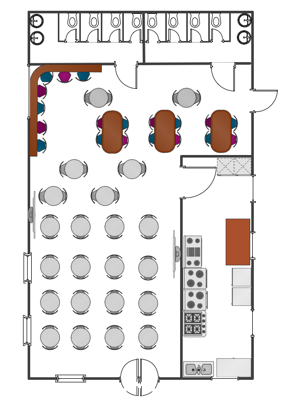
Picture: Cafe Floor Plan. Cafe Floor Plan Examples
Related Solution:
ConceptDraw DIAGRAM diagramming and vector drawing software extended with Electrical Engineering Solution from the Industrial Engineering Area of ConceptDraw Solution Park affords you the easiest and fastest way for designing professional looking Electrical Schematics.
Picture: Electrical Schematics
Related Solution:
Kansas is a U.S. state located in the Midwestern United States.
The vector stencils library Kansas contains contours for ConceptDraw DIAGRAM diagramming and vector drawing software. This library is contained in the Continent Maps solution from Maps area of ConceptDraw Solution Park.
Picture: Geo Map — USA — Kansas
Related Solution:
Systems Modeling Language (SysML) is a general-purpose modeling language for systems engineering applications.
ConceptDraw DIAGRAM diagramming and vector drawing software was extended with SysML Solution from the Software Development Area of ConceptDraw Solution Park specially to help systems engineers design various model systems with SysML.
Picture: SysML
Related Solution:
ConceptDraw DIAGRAM is a powerful diagramming and vector drawing software. Extended with Chemical and Process Engineering Solution from the Industrial Engineering Area of ConceptDraw Solution Park, it became the best Chemical Engineering software.
Picture: Chemical Engineering
Related Solution:
Easy charting software comes with beautiful chart templates and examples. This makes it easy to create professional charts without prior experience.
Picture: Chart Examples
Related Solutions:
The Line Graphs solution from Graphs and Charts area of ConceptDraw Solution Park contains a set of examples, templates and design elements library of scatter charts.
Use it to draw scatter graphs using ConceptDraw DIAGRAM diagramming and vector drawing software for illustrating your documents, presentations and websites.
Picture: Scatter Chart Examples
Related Solution:


