Electrical Symbols — Maintenance
Electrical maintenance - troubleshooting electrical circuit.Schematic drawings intended for maintenance may have the principal signal paths highlighted to assist in understanding the signal flow through the circuit. More complex devices have multi-page schematics and must rely on cross-reference symbols to show the flow of signals between the different sheets of the drawing.

Pic. 1. Maintenance Library
ConceptDraw DIAGRAM is a powerful software for creating professional looking electrical diagram quick and easy. For this purpose you can use the Electrical Engineering solution from the "Engineering" area of ConceptDraw Solution Park.
Electrical Engineering Solution for ConceptDraw DIAGRAM provides the stencils libraries of ready-to-use predesigned 926 vector symbols, templates and samples that make your electrical drawing quick, easy and effective.
26 libraries of the Electrical Engineering Solution of ConceptDraw DIAGRAM make your electrical diagramming simple, efficient, and effective. You can simply and quickly drop the ready-to-use objects from libraries into your document to create the electrical diagram.

Pic. 2. Electrical Engineering symbols
Electrical diagram software will assist you in drawing your electrical diagrams with minimal effort and makes it very easy for beginners.
Electrical symbols and smart connectors help present your electrical drawings, electrical schematic, wiring diagrams and blue prints.

Pic. 3. Electrical Symbols — Maintenance
Most of the electrical symbols can be changed in their appearance, styles and colors according to users' requirements. Electrical symbols are used to represent various electrical and electronic devices in a schematic diagram of an electrical or electronic circuit.
The following table lists some maintenance electrical symbols in our electrical diagram software.
| Symbol |
Meaning |
| Electrical Symbols — Maintenance |
 | Signal generator |
 | Linear element |
 | Relay contacts |
 | Relay coil |
 | Switch |
 | Composite circuit |
 | Amplifier |
 | Signal code, normal |
 | Signal code, secondary flow |
 | Reference signal |
 | Energize relay signal |
 | Transmitter pulse |
 | Test signal |
 | Feedback |
Circuit diagrams are used for the design (circuit design), construction (such as PCB layout), and maintenance of electrical and electronic equipment.
The diagrams are a big help when workers try to find out why a circuit does not work correctly.
How to Create an Electrical Diagram Using Maintenance Library
NINE RELATED HOW TO's:
ConceptDraw DIAGRAM Comparison with Omnigraffle Professional and MS Visio. All source ConceptDraw documents are vector graphic documents. They are available for reviewing, modifying, or converting to a variety of formats: PDF file, MS PowerPoint, MS Visio, and many other graphics formats.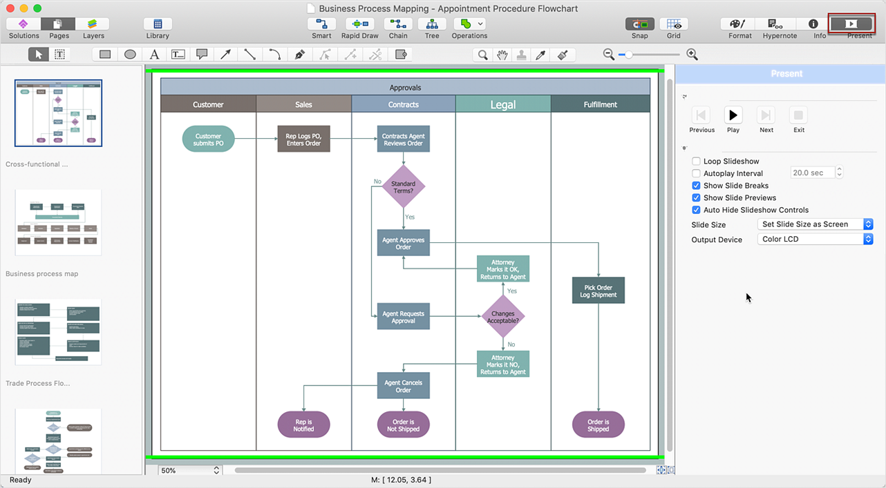
Picture: ConceptDraw DIAGRAM Comparison with Omnigraffle Professional and MS Visio
Related Solution:
ConceptDraw DIAGRAM diagramming and vector drawing software supplied with Chemical and Process Engineering Solution from the Industrial Engineering Area of ConceptDraw Solution Park is powerful and effective process engineering software.
Picture: Process Engineering
Related Solution:
Network infrastructure planning is a very important process in the network construction, and the share of time allocated to this within the scope of the entire project may reach 60-80%. A competent and thorough approach to planning contributes to the quick investment return, and also increases the reliability and flexibility of the final system, reducing the probability of additional costs related to the incorrect implementation.
Any planning begins with an analysis of the business requirements to the final system. Basic network parameters, which should be assessed are the scalability, accessibility, cost, speed and safety.
Speed and cost are often mistaken for the most important parameters, and the rest of the parameters aren't even remembered. This is not entirely correct. Initially, it is necessary to assess the business plans for the future, because sometimes it is more profitable to invest more money in the beginning. If the business is to develop, then, consequently, demands on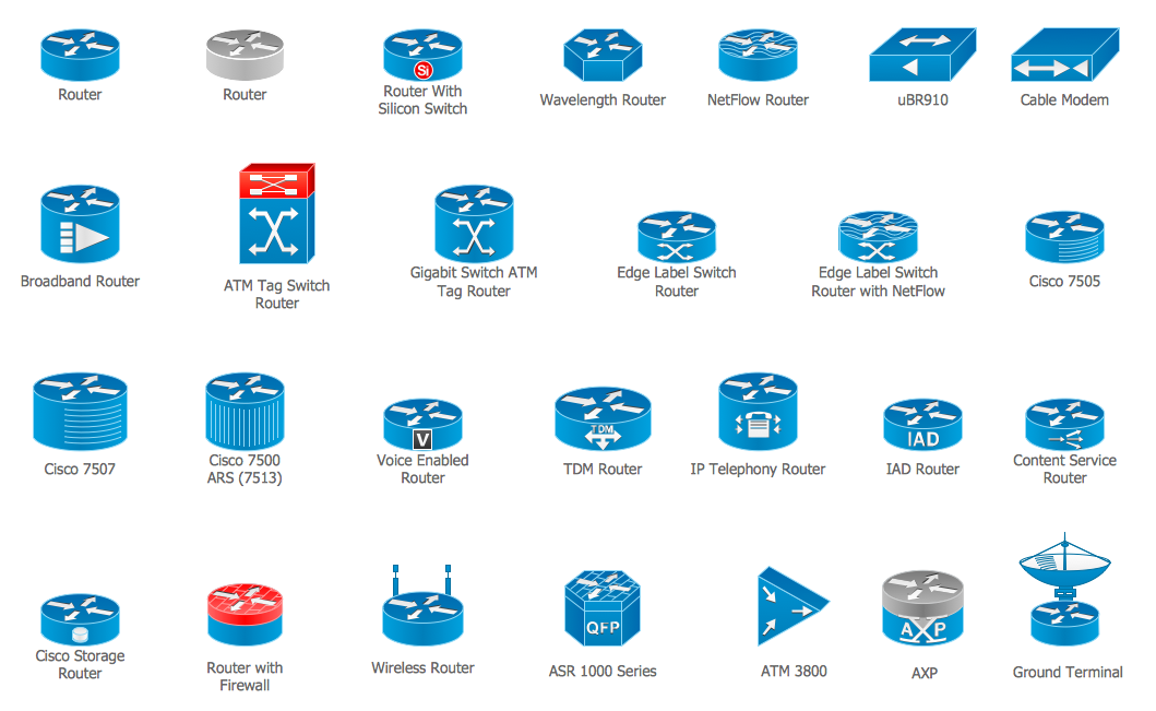
Picture: Cisco Routers. Cisco icons, shapes, stencils and symbols
Related Solution:
ConceptDraw DIAGRAM is perfect for software designers and software developers who need to draw Network Active Directory Diagrams.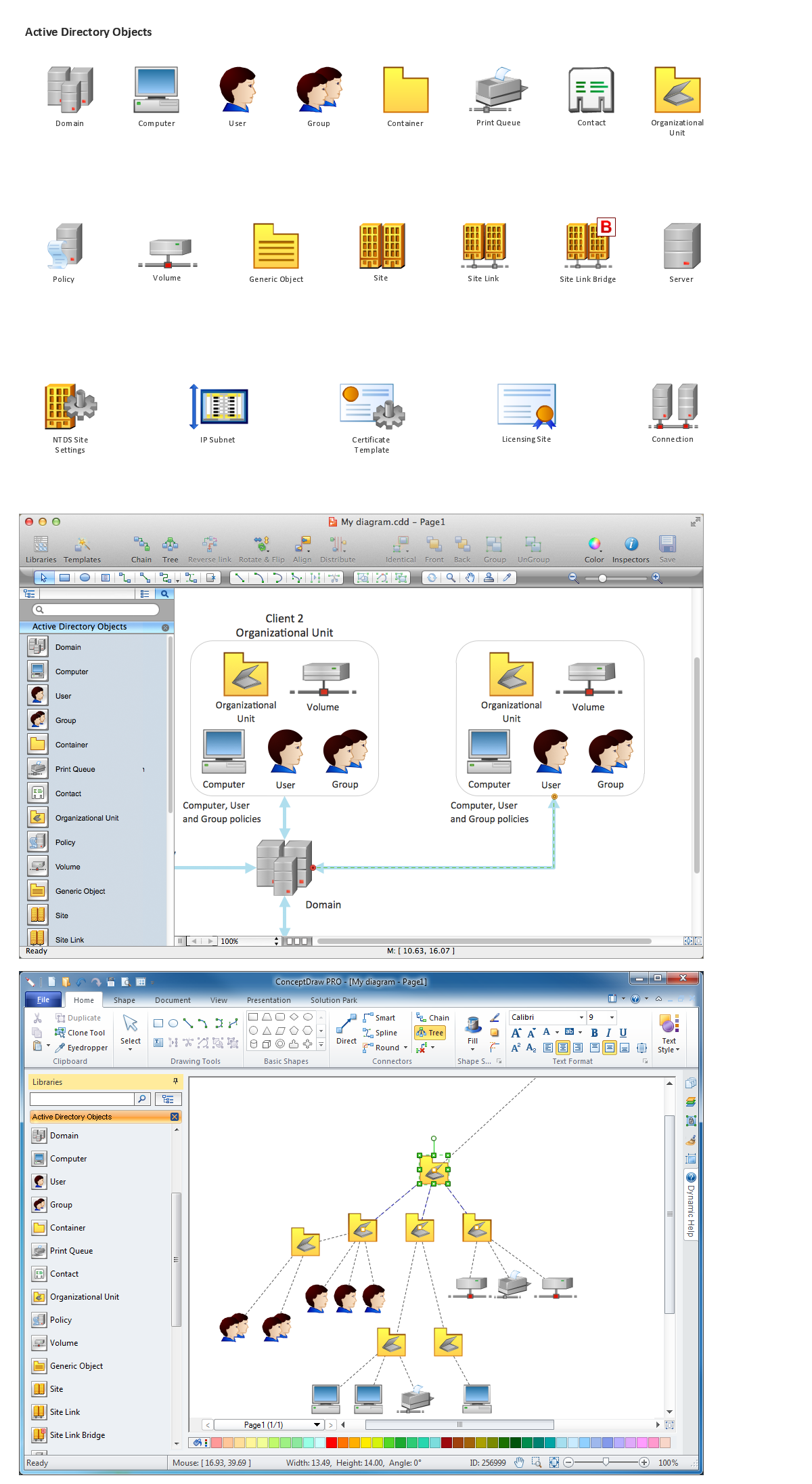
Picture: Network Diagramming Software for Network Active Directory Diagrams
You need to draw professional looking BPMN diagrams quick and easy? Pay please your attention on ConceptDraw DIAGRAM diagramming and vector drawing software. Extended with Business Process Diagram Solution from the Business Processes Area it will be ideal for your.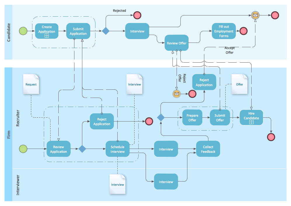
Picture: BPMN
Related Solution:
When you decide to represent data without spending lots of time you can effectively generate, change, and update your presentation to best meet your needs with ConceptDraw MINDMAP.
Picture: 3 Ways to Quickly Create Excellent Presentations
Related Solution:
A cozy atmosphere is crucial for the success of any cafe or restaurant. To provide it, you should use restaurant floor plan software at the stage of design. If your establishment is located conveniently and has a harmonic atmosphere inside it, this is bound to be a success.
This sample Restaurant floor plan illustrates the possibilities of ConceptDraw solution for Cafe and Restaurant plans. It represents the location of the restaurant's main hall with its furnishing as well as a plan of kitchen and toilets. Generally, Cafe and Restaurant Plans solution has a big set vector images of tables, seats, lightening, etc. Using them you will be able to plan the restaurant of your desire with an incredible design and spirit.
Picture: Restaurant Floor Plan Software
Related Solution:
The metal–oxide–semiconductor field-effect transistor (MOSFET, MOS-FET, or MOS FET) is a type of transistor used for amplifying or switching electronic signals.
Although the MOSFET is a four-terminal device with source (S), gate (G), drain (D), and body (B) terminals, the body (or substrate) of the MOSFET is often connected to the source terminal, making it a three-terminal device like other field-effect transistors. Because these two terminals are normally connected to each other (short-circuited) internally, only three terminals appear in electrical diagrams. The MOSFET is by far the most common transistor in both digital and analog circuits, though the bipolar junction transistor was at one time much more common.
26 libraries of the Electrical Engineering Solution of ConceptDraw DIAGRAM make your electrical diagramming simple, efficient, and effective. You can simply and quickly drop the ready-to-use objects from libraries into your document to create the electrical diagram.
Picture: Electrical Symbols — MOSFET
Related Solution:
ConceptDraw MINDMAP is effective Mind Mapping Software with rich clipart galleries, extensive drawing capabilities, a large quantity of examples of professionally designed mind maps on the different themes and powerful import and export capabilities.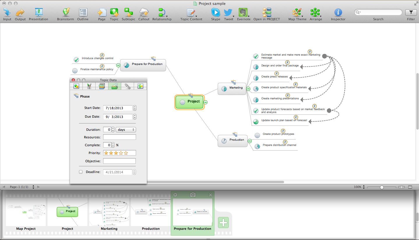
Picture: Mind Mapping Software
Related Solution:


 . To connect elements using this tool, drag the connector from one connect dot to another.You can use Layers to place connections on different layers.

