What is Electrical Engineering? Basic Electrical Engineering Software
What is Electrical Engineering?
Electrical engineering is known to be a popular nowadays field of engineering that deals, in general, with the application and study of electricity, electromagnetism, and electronics, which became a first identifiable occupation in the 19th century after commercialization of the electric telegraph, electric power distribution, the telephone and use. Nowadays, the broadcasting as well as the recording media made electronics a part of everyday life. After the transistor was invented, and so the integrated circuit later, the cost of all electronics was brought down to the point when they can be used by almost anyone today.

Example 1. Electrical Engineering Software — ConceptDraw DIAGRAM
Electrical Engineering Types
Nowadays, the electrical engineering has been subdivided into lots of subfields. Different types of electrical engineering include electronics, computer engineering, power engineering, digital computers, telecommunications, radio-frequency engineering, microelectronics, signal processing, control systems, and instrumentation. Many of the mentioned sub-disciplines are known to be overlapping with each other as well as with other engineering branches. Thus, there’s a huge number of specializations within the mentioned field of activity: hardware engineering, electromagnetics and waves, microwave engineering, power electronics, nanotechnology, electrochemistry, mechatronics, electrical materials science, renewable energies, etc.
Electronics Engineering
Electronics engineering is focused on the development of products and systems using electronic technologies. It uses active components in addition to passive devices. For example, semiconductor devices to control and amplify electric current flow. Electronics engineering includes analog and digital electronics, signal processing, computer engineering, systems engineering, embedded systems, power electronics systems, radio engineering, telecommunications, control systems, consumer electronics, instrumentation engineering, photonics, robotics.
Professional electrical engineers usually have a degree in electronic engineering or electrical engineering. Having the professional certifications and being members of the professional bodies (the Institution of Engineering and Technology, the Institute of Electrical and Electronics Engineers, etc.), all practicing engineers still need a drawing tool that can help to make any engineering-related drawings.
If you work as an electronics or electrical engineer, then you might definitely be involved in work in lots of different industries having the required skills known to be variable. The range may be within the basic circuit theory all the way up to the management skills, which are required of the project managers. The equipment, same as the appropriate tools, any individual engineer needs on an everyday basis, which is all variable: voltmeter, top-end analyser, sophisticated design, manufacturing software, app for electrical engineering design as well as drawings electrical engineering software. Having the best electrical design program means a lot in any work of any engineer and so the ConceptDraw DIAGRAM diagramming and drawing app for electrical engineering and electronics engineering can solve many problems helping complete the needed tasks.

Example 2. Electronic Engineering — Fluorescent Lamp Smart Starter
Telecommunications Engineering
Telecommunications engineering is an electronics engineering field closely related to electrical engineering, systems engineering, computer science, and digital technologies. It is involved in the design and development systems of communication at a distance, voice and data communications systems. Telephone and data networks, internet, radio, TV, satellites, and deep space applications are managed by telecommunications engineers, who design, construct, develop, install, and maintain corresponding telecommunications equipment and systems. Telecommunications engineering field also overlaps with broadcast engineering.
Telecommunications include a wide range of information-transmitting technologies, communications infrastructures, landline and mobile phone services, internet and telecommunication channels, protocols, input and output devices, telecommunication processors, control software, messages. Telecommunications engineers are responsible for a variety of communication networks, telephone and internet networks, radio and television communications. The modern transmission methods include copper-wire networks and high-speed digital transmission methods, fiber optic cabling, mobile telecommunications, IP networks, satellites and wireless communication technologies, which affect changes and overall improvement of processes in different fields.
The process of signal processing is a part of the electrical engineering activity, dealing with the manipulation and analysis of the signals. Such signals can be analog, varying according to the given information, or digital, varying due to the discrete values that represent the information. For the mentioned analog signals, the process of signal processing is known to be involving the filtering as well as the amplification of the audio signals for the modulation and demodulation of signals and audio equipment used for telecommunications. For different digital signals, the process of signal processing can also involve error detection, error correction of the digitally sampled signals as well as compression.

Example 3. Telecommunications Engineering — CB Intercom Circuit
Control Systems Engineering
Control systems are used in engineering and automation to regulate how devices operate in real time. Control engineering deals design, development, and maintaining control systems and control systems equipment. Sensors and detectors are used to measure the output performance that is controlled to provide corrective feedback, especially in automatic control systems.
Signal processing itself is known to be a very intensive as well as mathematically oriented area, which can form the core of digital signal processing, expanding with the new applications in every single field of electrical engineering: communications, radar, control, audio engineering, power electronics, biomedical engineering, and broadcast engineering. Nowadays, lots of the already existing analog systems are known to be replaced with their digital counterparts as it is more common to use the digital devices. Nevertheless, the analog signal processing is still important in the design of lots of different control systems.

Example 4. Control Systems Engineering — Lightdimmer Phase Control Circuit
Computer Engineering
The so-called computer engineering deals with electronic engineering and computer systems as well as the design of computers, involving the design of new hardware or PDAs, supercomputers, tablets, or the use of computers themselves in order to control some industrial plant, for example. Computer engineering deals with the development, construction, testing, analysis, integration, evaluation, and upgrade of computer systems both in terms of hardware and software. This area also includes robotics, artificial intelligence (AI), nano and micro technologies, microcontrollers and microprocessors development, computer architecture and operating systems, computer-controlled systems, communication technologies, and computer networks.
Computer engineering is closely related to medical technologies, automobile industry, mobile techniques, and many other fields. Such specialists (the computer engineers) are also known to be working on some system's software or being involved in the process of designing some complex electrical engineering software systems. Desktop computers are known to be representing only a tiny fraction of the devices any computer engineer can work on, when the computer-like architectures can be found now in a huge range of devices, such as DVD players, video game consoles, and others.

Example 5. Computer Engineering — Boolean Algebra Operations
What Do Electrical Engineers Create
Electrical engineers are in great demand today. They are developers, designers, and innovators in many fields. Because the electricity and electrical systems are those that keep the world running and affect its development. In a modern digital world, electrical engineers work everywhere and are involved in multifarious issues. These include the development, creation, and maintaining both basic home appliances and complex systems, networks, control systems, telecommunications systems, energy systems, transportation, industries, robotics, and AI systems. Electrical engineers are responsible for designing, developing, manufacturing, building, installing, testing, supervising, and maintaining electrical equipment and systems, complex electrical parts and mechanisms. They provide the optimization of functionality, updating, finding vulnerable points and eliminating them to keep running smoothly the electric motors, electrical components of vehicles, propulsion systems, navigational systems, power generation and power supply equipment, fusion systems, aeronautic and aerospace technics, computer engineering, microelectronics, etc.
ConceptDraw DIAGRAM Electrical Engineering Software Benefits
In case your work is related to such field of engineering, then you might find the ConceptDraw DIAGRAM diagramming and drawings electrical engineering app as well as the Electrical Engineering Solution downloaded from the ConceptDraw STORE — another product of CS Odessa — to be very useful. Having the mentioned applications as well as the described solution for electrical design program means having all the necessary tool for achieving your goals in engineering.

Example 6. Electrical Engineering Solution for electrical design program in ConceptDraw STORE
Use Cases
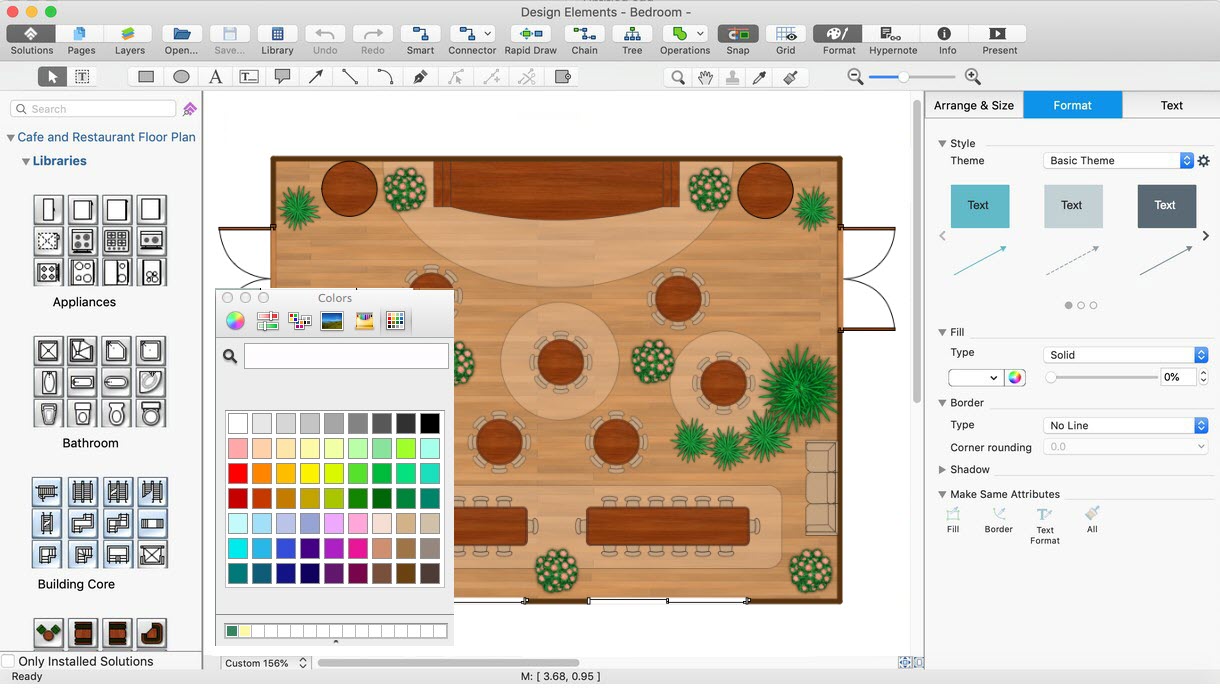
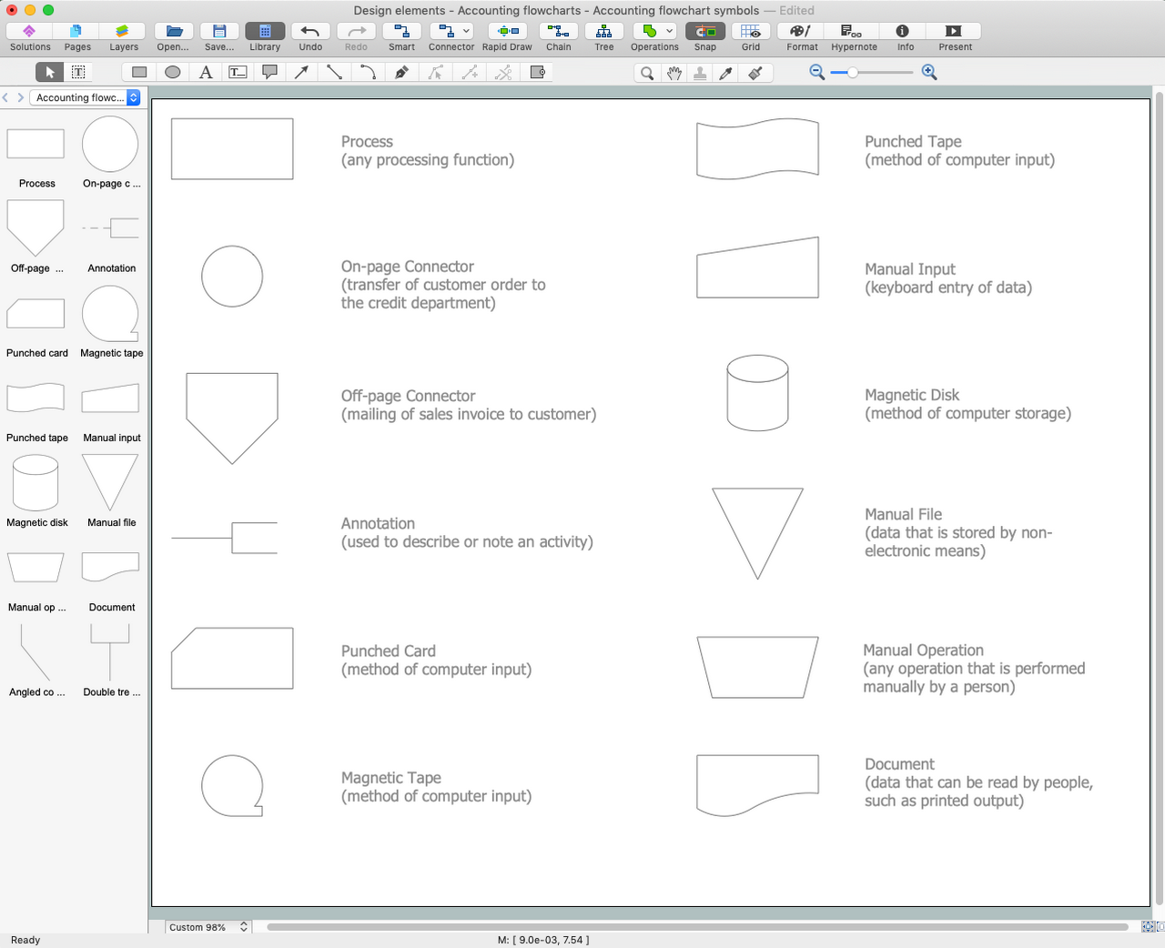
Electrical Engineering Solution for ConceptDraw DIAGRAM electrical engineering app contains plenty of libraries with predesigned vector engineering electrical symbols for intuitive drawing different types of electrical engineering schematics and diagrams. A collection of included ready-made samples is a perfect base to make your drawings fast and easily. Any sample suits to be used as a template for a quick start.
There are all together twenty-six stencil libraries available for being used by any user of ConceptDraw DIAGRAM basic electrical engineering app and so ConceptDraw STORE, such as “Design Elements — Qualifying” one, including the visual representations of such terms as different kinds of Radiation, Multiple-phase windings, etc. The other stencil libraries are “Design Elements — MOSFET”, including the representations of the different kinds of the metal-oxide-semiconductor field-effect transistor types, “Design Elements — Composite Assemblies”, including the representations of Touch sensor, OC computer, etc, and other.
Summary
Working on the desktop computer, tablet or laptop, you can always use any of the solutions provided by the CS Odessa specialists who keep them all in the ConceptDraw STORE application — a very useful tool, which is always available to be downloaded from this site same as the ConceptDraw STORE one. Having the Electrical Engineering Solution for ConceptDraw DIAGRAM electrical engineering software downloaded to your desktop means having enough tools for creating any electrical engineering-related drawings, such as design elements and the pre-created templates and samples.