Made with
ConceptDraw
DIAGRAM 18

Total Quality Management Definition

Total quality management is the one known to be consisting of some organization-wide efforts put in order to install and to make some climate in which this organization can continuously improve its ability to deliver the high-quality products and services to its customers permanently.

There are no widely agreed-upon approaches within the total quality management activity, that is why all the efforts are known to be drawing heavily on the previously developed techniques and tools of the quality control. Enjoying a widespread attention during the late 1980s as well as the early 1990s before being overshadowed by ISO 9000, Six Sigma and Lean manufacturing, TQM is still a very popular term, especially in the organizations that are focused on making the high-quality goods.

Having no widespread agreement as to what time quality management is as well as what the exact actions that it actually requires of organizations, there is a review of the original United States Navy effort that gives a rough understanding of what it is. Thus, the key concepts in the TQM effort that are undertaken by the Navy in the 1980s include such statements as the quality should be defined by the customers' requirements, top management has the direct responsibility for all the quality improvement and that the increased quality may only come from a systematic analysis as well as a systematic improvement of different work processes within an organization.

Also, the quality improvement within the total quality management definition is known to be a continuous effort as well as a conducted throughout the organization. The Navy used such tools and techniques as the so-called “PDCA cycle” in order to drive different issues to resolution, the ad hoc cross-functional teams that are known to be similar to the quality circles which are responsible for addressing all the immediate process issues, etc.

The previously mentioned techniques used within the TQM also involve arranging the cross-functional teams taking the responsibility for the improvement of the different processes over the long term as well as managing the active participation through steering committees.

Total Quality Management Definition *

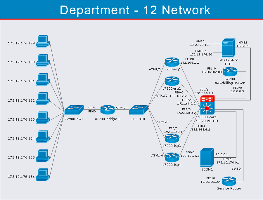
Pic.1 Total quality management (TQM) flowchart template

Use of the Seven Basic Tools of Quality for analyzing all the quality-related issues can be an option to go for. Having the need of creating the drawing that may help solve the problems the managers face there is always an opportunity to get a very useful and professionally developed diagramming and drawing software such as the ConceptDraw DIAGRAM one.

The Total Quality Management (TQM) Diagrams Solution is one of many that are available to be downloaded from the ConceptDraw STORE application to be used for making the TQM diagrams as well as many other schemes.

Total Quality Management Definition

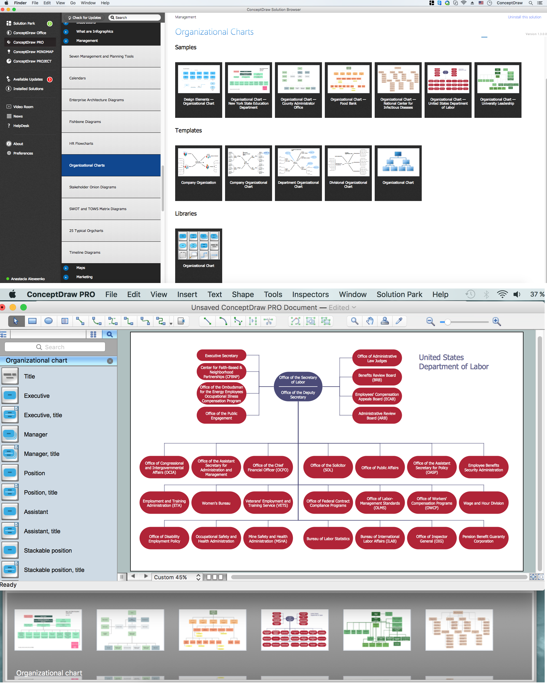
Pic.2 Total quality management (TQM) solution

The Seven Basic Tools of Quality is simply a designation that can be given to some fixed set of different graphical techniques that can be identified as being most helpful in troubleshooting issues being related to quality. Being called “basic”, they are suitable for all those people who do not have as much formal training in statistics. Also, they are called as “basic” for a reason of them being used for solving the vast majority of quality-related issues.

All seven tools are cause-and-effect diagram (it is also known as the Ishikawa or "fishbone" diagram), check sheet, control chart, histogram, Pareto chart, scatter diagram and flow chart (also known as “run chart”). Making any of the mentioned drawings with the help of the ConceptDraw STORE application, and the Total Quality Management (TQM) Diagrams Solution in particular, can take only a few minutes as using all the previously created templates is easy making the new charts in this way.

Some of the TQM tools were possibly introduced by Kaoru Ishikawa who was known to be influenced by a series of lectures of W. Edwards Deming that had been given to the Japanese engineers and scientists in 1950. At that time, those companies that had some problems in training their workforces in a statistical quality control were found that the complexity of the subject intimidated the vast majority of their workers scaling back the training in order to focus on the simpler methods which suffice for most quality-related issues.

The Seven Basic Tools are known to be standing in a contrast to more advanced statistical methods. Such methods may be surveyed sampling, statistical hypothesis testing, the design of experiments, acceptance sampling, multivariate analysis and other During the 1990s, most of the standards bodies from Belgium, Germany, France, the United Kingdom and Turkey attempted to standardize total quality management. While many of the mentioned standards have since been already withdrawn, they all are still effectively superseded by ISO 9000.methods that were developed in the field of operations research.

The Project Management Institute is known to be referring the Seven Basic Tools in A Guide to the Project Management Body of Knowledge. It was done to make an example of a set of the most general tools that were accepted to be useful for controlling and planning the project quality.

During the 1990s, most of the standards bodies from Belgium, Germany, France, the United Kingdom and Turkey attempted to standardize total quality management. While many of the mentioned standards have since been already withdrawn, they all are still effectively superseded by ISO 9000.

The definition of the total quality management was given in this article but to actually get down to making the needed TQM drawing, such as a TQM diagram, all the needed tools can be found in the Total Quality Management (TQM) Diagrams Solution from the ConceptDraw STORE application to be used in the ConceptDraw DIAGRAM diagramming and drawing application.


TEN RELATED HOW TO's:
A flowchart is a powerful tool for examining processes. It helps improving processes a lot, as it becomes much easier to communicate between involved people, to identify potential problems and to optimize workflow. There are flowcharts of different shapes, sizes and types of flowchart vary from quite basic process flowcharts to complex program flowcharts. Nevertheless, all these diagrams use the same set of special symbols like arrows to connect blocks, parallelogram to show data receiving or rectangles for showing process steps. Basic flowcharts are used to represent a simple process algorithm. A basic flowchart notation consists of rectangles (business processes), arrows (the flow of information, documents, etc.). The same notation is used in items such as the "decision", which allow you to do the branching. To indicate the start of the entire business process and its termination can be used the "Terminator" element. The advantages of Basic Flowchart are simplicity and clarity. With it you can quickly describe the business process steps. Creating of Basic Flowchart does not require any special knowledge, as easily understand by employees with different levels of education and IQ.Types of Flowchart — Overview
Picture: Types of Flowchart: Comprehensive Overview
Related Solution:
Use samples and templates to describe your own quality processes, brainstorm, and structure quality issues.Quality Mind Maps - samples and templates *
Picture: Quality Mind Maps - samples and templates
Related Solution:
ConceptDraw DIAGRAM diagramming and vector drawing software extended with Seven Basic Tools of Quality solution from the Quality area of ConceptDraw Solution Park provides effective tools for quality control and helps design any types of quality-related diagrams.Seven Basic Tools of Quality — Quality Control *
Picture: Seven Basic Tools of Quality — Quality Control
Related Solution:
A database is a data collection, structured into some conceptual model. Two most common approaches of developing data models are UML diagrams and ER-model diagrams. There are several notations of entity-relationship diagram symbols and their meaning is slightly different. Crow’s Foot notation is quite descriptive and easy to understand, meanwhile, the Chen notation is great for conceptual modeling. An entity relationship diagrams look very simple to a flowcharts. The main difference is the symbols provided by specific ERD notations. There are several models applied in entity-relationship diagrams: conceptual, logical and physical. Creating an entity relationship diagram requires using a specific notation. There are five main components of common ERD notations: Entities, Actions, Attributes, Cardinality and Connections. The two of notations most widely used for creating ERD are Chen notation and Crow foot notation. By the way, the Crow foot notation originates from the Chen notation - it is an adapted version of the Chen notation.ERD Symbols and Meanings
Picture: ERD Symbols and Meanings
Related Solution:
ConceptDraw DIAGRAM diagramming and vector drawing software extended with Total Quality Management (TQM) Diagrams solution from the Quality area of ConceptDraw Solution Park is effective software for Total Quality Management.Total Quality Management *
Picture: Total Quality Management
Related Solution:
There are many ways to describe a database structure. One of the most usual is to draw an entity relationship diagram (ERD) using a Crow’s Foot notation to represent database elements. If you don’t want to draw it on paper, you should use an appropriate software. An entity-relationship (ER) diagram is used to show the structure of a business database. ERD represents data as objects (entities) that are connected with standard relationships symbols which Illustrate an association between entities. ERD, there is a wide range of ERD notations used by data bases architects for reflecting the relationships between the data entities. According to the crow’s foot notation relationships are drawn as single labeled lines designating a certain kinds of relationship. Crow foot notation is a most frequently used ERD standard, because of improved readability of diagrams, with a more accurate use of space on the page.Entity Relationship Diagram - ERD - Software for Design  <br>Crows Foot ER Diagrams *
Picture: Entity Relationship Diagram - ERD - Software for Design Crows Foot ER Diagrams
Related Solution:
No one can imagine a geography class without such educational stuff as a geo map or a globe. As for one of the biggest countries in North America, the United States of America Map is present in every American school or college. It’s easier to remember all the states if you look on the map more often. The following sample represents the map of USA. This precise map has names of all states of America. The different colors which are used to indicate each state add the visuality and brightness to the whole map. The ConceptDraw USA Maps solution - one of a family of ConceptDraw Maps solutions. Any country invokes a big piece of data: geographical, political, statistical, etc. A simple way of representing this data is to design maps that will show a certain item in relation to a particular area of Earth.United States of America Map
Picture:
How to Draw the US Map?
ConceptDraw Diagram Software for Easy USA Map Drawing
Related Solution:
Flowcharts are helpful in understanding a complicated process. ConceptDraw DIAGRAM allows you to creating a simple flowchart. The ability to create flowcharts is contained in the Flowcharts solution. The solution provides a set of special tools for creating flowcharts.Creating a Simple Flowchart *
Picture: Creating a Simple Flowchart
Related Solution:
A process flowchart is a picture of the separate steps of a process in sequential order.Use ConceptDraw DIAGRAM software and the vector stencils from object libraries are designed objects you can use adding to process flowcharts for the best result.Create Process Flowcharts *
Picture: Create Process Flowcharts
Related Solution:
ConceptDraw DIAGRAM software extended with Fishbone Diagrams solution from the Management area of ConceptDraw Solution Park is perfect for Cause and Effect Diagram creating. It gives the ability to draw fishbone diagram that identifies many possible causes for an effect or a problem. Causes and Effects are usually grouped into major categories to identify these sources of variation. Causes and Effects in the diagram show relationships among various factor. Fishbone diagram shows factors of Equipment, Process, People, Materials, Environment and Management, all affecting the overall problem.Cause and Effect Diagram *
Picture: Cause and Effect Diagram
Related Solution:
ConceptDraw
DIAGRAM 18