Made with
ConceptDraw
DIAGRAM 18

Interior Design. Piping Plan — Design Elements

Every apartment needs renovation from time to time, as some home systems such as wiring or plumbing may fall out. When developing the future design of a piping system, the engineer should take into account many aspects. Replacing the worn plumbing begins with the choice of materials and sizes of pipes for the new system. Each proposal has its own pros and cons that should be considered before purchasing. It is also relevant to draw attention to temperature changes that might effect pipes, such as freezing or thermal expansion. Let’s take a closer look at possible pipes materials.

Recently, steel pipes were the most common, and now they can still be purchased. The most important advantage of steel is that it is eco-friendly and the fact that they have passed the test of time and pipes of good quality can function for more than 50 years. Remaining pros: high operating pressure and temperature, as well as small thermal expansion. The negative sides of steel pipes include their big weight; inner diameter gradually decreases due to corrosion and the complexity of the system assembling and altering. It is also worth noting that even a temporary lack of water in the pipes causes their rapid rusting which gives water a metallic taste.

Plastic (Polypropylene) pipes are a good alternative to the steel and are characterized by ease of installation, low weight and price, durability and a complete absence of corrosion. Currently, it is the most used option. When connecting to the existing metal communications one should use fittings like unions or elbows. Due to thermal expansion, it is recommended to use a double-walled pipe system, which allows creating an interstitial space between the diameters of the two pipes.

Another option is PEX-AL-PEX pipes, which consist of three layers: the outer layer of high density polyethylene, a middle layer of aluminum foil and the inner layer of polyethylene.

Piping plan — Design elements libraries

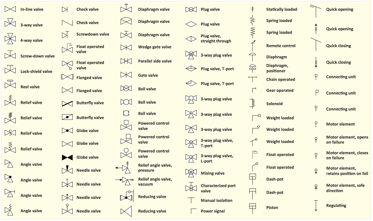
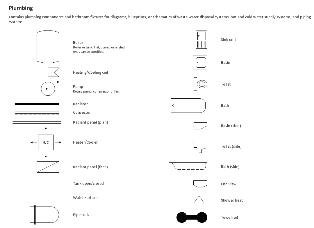
Vector stencils libraries Piping 1, Piping 2 and Valves contain shapes of pipes and valves for drawing plumbing and piping building interior design plans, schematic diagrams, blueprints, or technical drawings of waste water disposal systems, hot and cold water supply systems using ConceptDraw DIAGRAM diagramming and vector drawing software.

These libraries are included in Plumbing and Piping Plans solution from Building Plans area of ConceptDraw Solution Park.

Piping Plan Solution

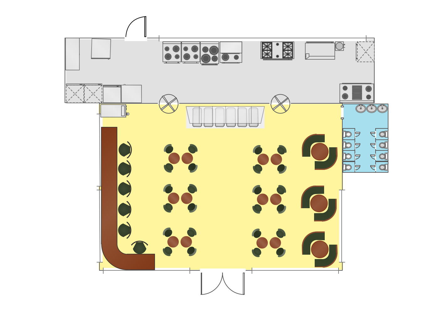
Sample 1. Interior Design Software. Piping Plan solution

The Pipes 1 library contains 28 symbols:

  • General joint
  • Butt weld
  • Soldered / solvent
  • Screwed joint
  • Socket and spigot
  • Sleeve joint
  • Socket weld
  • Flanged / bolted
  • Swivel joint
  • Electrically bonded
  • Electrically insulated
  • End caps
  • Strainer
  • Flame arrester
  • Bursting disc
  • Separator
  • Drain silencer
  • Exhaust silencer
  • Y strainer
  • Tundish
  • Bell mouth
  • Exhaust head
  • Liquid seal open/closed
  • Open vent
  • Syphon drain
  • Hydrant

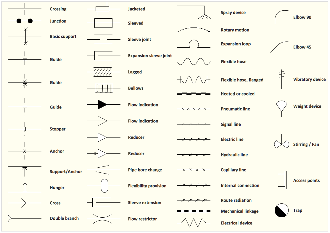
The Pipes 2 library contains 42 symbols.

  • Crossing
  • Junction
  • Cross
  • Double branch
  • Elbow 45
  • Elbow 90
  • Heated or cooled
  • Pneumatic line
  • Signal line
  • Electric line
  • Hydraulic line
  • Capillary line
  • Internal connection
  • Route radiation
  • Jacketed
  • Lagged
  • Pipe bore change
  • Mechanical linkage
  • Electrical device
  • Vibratory device
  • Weight device
  • Spray device
  • Rotary motion
  • Stirring / fan
  • Basic support
  • Guide
  • Stopper
  • Anchor
  • Support / anchor
  • Hunger
  • Access points
  • Trap
  • Flexibility provision
  • Bellows
  • Expansion loop
  • Sleeve extension
  • Flow restrictor
  • Guide
  • Sleeved
  • Sleeve joint
  • Expansion sleeve joint
  • Flow indication
  • Reducer
  • Arrow
  • Flexible hose

The Valves library contains 37 symbols.

  • Flanged
  • In-line valve
  • 3-way valve
  • 4-way valve
  • Screw-down valve
  • Lock-shield valve
  • Reel valve
  • Lock-shield valve
  • Screw-down valve
  • Relief valve
  • Angle valve
  • Check valve
  • Screwdown valve
  • Float operated valve
  • Flanged valve
  • Butterfly valve
  • Globe valve
  • Needle valve
  • Diaphragm valve
  • Wedge gate valve
  • Parallel side valve
  • Gate valve
  • Ball valve
  • Powered control valve
  • Relief angle valve
  • Reducing valve
  • Plug valve
  • Straight through
  • 3-way plug valve
  • Plug valve, T-port
  • Plug valve, L-port
  • 3-way plug valve
  • Mixing valve
  • Characterized port valve
  • Manual isolation
  • Power signal
  • Statically loaded
  • Actuating method
  • Spring loaded
  • Remote control
  • Diaphragm
  • Positioner
  • Chain operated
  • Gear operated
  • Solenoid
  • Weight loaded
  • Float operated
  • Dash-pot
  • Piston
  • Quick opening
  • Quick closing
  • Connecting unit
  • Motor element
  • Safe direction
  • Retains position on fail
  • Regulating
  • Method of control
Interior Design. Piping Plan — Design Elements * Interior Design. Design Elements — Pipes Interior Design. Design Elements — Valves

Sample 3. Interior Design Software. Design Elements — Piping Plan
for Mac OS X and Windows

Solution Building Plans from ConceptDraw Solution Park provides 4 vector stencils libraries with 128 design elements as pipes, valves and other sanitary equipment for drawing Plumbing & Piping Plans.

Use ConceptDraw DIAGRAM diagramming and vector drawing software enhanced with Building Plans solution to draw your own plumbing & piping plans, annotated diagrams or schematics of waste water disposal systems, hot and cold water supply systems, water lines, plumbing systems and waste water engineering using plumbing floor plan, plumbing layout plan, half pipe plans, pipe bender plans and plumbing plan symbols.

Read more about Home and Landscape design

TEN RELATED HOW TO's:
When talking about engineering, one should define all the terms used, so anybody could understand the topic. Typical network glossary contains definitions of numerous network appliances, types of networks and cable systems. The understanding of basic is crucial for server management, network administration and investigating problems. The network glossary defines terms related to networking and communications. The most of glossary items has their visual representation in ConceptDraw DIAGRAM libraries of the Computer Network Diagrams solution. This illustration presents a local area network (LAN) diagram. It designed to show the way the interaction of network devices in a local network. The diagram uses a library containing symbols of network equipment, connections and the end-point devices such as network printer, hubs, server, modem and finally computers (PC, mac, laptop). This diagram depicts a physical LAN topology.Network Glossary Definition *
Picture: Network Glossary Definition
Related Solution:
Nodes of any computer network are somehow organized in a hierarchy or a layout. Some of the common layouts like star network topology are more reliable and some like ring topology withstand high loads better. It is also important to distinguish logical topologies from physical. This diagram represents a typical view of the star network topology. The star network topology is one of the most frequently used network topologies in the majority of office and home networks. It is very popular because of its low cost and the easy maintenance. The plus of the star network topology is that if one computer on the local network is downed, this means that only the failed computer can not send or receive data. The other part of the network works normally. The minus of using star network topology is that all computers are connected to a single point-switch, or hub. Thus, if this equipment goes down, the whole local network comes down.Star Network Topology *
Picture: Star Network Topology
Related Solution:
ConceptDraw DIAGRAM diagramming and vector drawing software extended with Gym and Spa Area Plans solution from Building Plans area of ConceptDraw Solution Park contains a set of examples, templates and design elements libraries for drawing Gym Workout Plan, Gym Floor Plan, Gym Layout Plan, Spa Floor Plan, Fitness Plan, etc.Gym Workout Plan *
Picture: Gym Workout Plan
Related Solution:
Intelligent Services Gateway (ISG) is a feature set that is available on the Cisco Routers. ISG provides the session management, the structured framework, the policies for management the various access networks, provides the information about the session bandwidth and network accessibility. This example was created in ConceptDraw DIAGRAM using the Computer and Networks solution from the Computer and Networks area of ConceptDraw Solution Park and shows the Intelligent Services Gateway (ISG) network.Intelligent Services Gateway (ISG) network. <br>Computer and Network Examples *
Picture: Intelligent Services Gateway (ISG) network. Computer and Network Examples
Related Solution:
ConceptDraw DIAGRAM diagramming and vector drawing software extended with Specification and Description Language (SDL) Solution from the Industrial Engineering Area of ConceptDraw Solution Park provides powerful drawing tools for quick and easy creating well-designed FSM diagrams.FSM — Finite-state Machine *
Picture: FSM — Finite-state Machine
Related Solution:
ConceptDraw DIAGRAM extended with Gym and Spa Area Plans solution from Building Plans area of ConceptDraw Solution Park is ideal software for quick and simple drawing professional looking Gym Floor Plan.Gym Floor Plan *
Picture: Gym Floor Plan
Related Solution:
There are three main types of organizational structures which can be adopted by organizations depending on their objectives: functional structure, divisional structure, matrix structure. ConceptDraw DIAGRAM diagramming and vector drawing software enhanced with 25 Typical Orgcharts solution from the Management area of ConceptDraw Solution Park is ideal for designing diagrams and charts of any organizational structure types.Organizational Structure Types *
Picture: Organizational Structure Types
Related Solution:
A circuit diagram is sometimes also called an elementary diagram, electronic schematic or electrical diagram circuits. It is essential in construction of any electronic equipment. Among many digital drawing tools available, ConceptDraw DIAGRAM is a leading circuits and logic diagram software, affording for easy and quick creation of even the most advanced and complex diagram designs. This makes it a perfect choice for computer science and any kind of electronic engineering. This drawing includes the graphic symbols that may be in use while creating a logic circuit diagram. The diagrams of such kind are used in the electronics industry. The logic symbol depicts a device that realizes a Boolean type functions. Practically a logic symbol means transistor, diodes, relays, and other mechanical or optical details which provide function of closing or opening "gates". Totally the logic circuits can involve millions of gates. ConceptDraw Electrical Engineering solution gives the opportunity to create a circuit diagrams both simple and difficult.Circuits and Logic Diagram Software *
Picture: Circuits and Logic Diagram Software
Related Solution:
Use ConceptDraw DIAGRAM software as powerful electrical engineering software and apply switches and relays electrical symbols in ✔️ electrical circuit diagrams, ✔️ electrical drawings, ✔️ electrical schematics, ✔️ wiring diagrams, ✔️ electrical blueprintsElectrical Symbols — Switches and Relays in ConceptDraw DIAGRAM
Picture: Electrical Symbols — Switches and Relays
Related Solution:
The first thing that your clients will see, is your restaurant's interior. It doesn’t matter, whether you own a Michelin-starred restaurant or a lunch counter, you will need a restaurant floor plan that will reflect every detail of the establishment’s interior. It is the second most important thing after the menu. Restaurant essentials include kitchen area, dining area, restrooms, bar area, staff quarters. Designing a layout of cafe and restaurant floor plan is a real art. It should be beautiful restaurant seating plan which convenient for visitors. Restaurant essentials include kitchen area, dining area, restrooms, bar area, staff quarters. Being planned wisely a layout of restaurant floor plan and restaurant seating chart (cafe floor plan or bar) guides to prosperous sales and good profit. Making a restaurant floor plan or restaurant seating chart involves many different elements that can be managed using ConceptDraw Cafe and Restaurant Floor Plan solution. Cafe and Restaurant library delivers a number of vector graphic objects for depicting various layouts of any style and design establishments. ConceptDraw DIAGRAM is great and simple restaurant floor plan software with thousands features.Restaurant Floor Plan *
Picture: Restaurant Floor Plan
Related Solution:
ConceptDraw
DIAGRAM 18