Cisco Design
Cisco Network Diagram

Cisco uses its own brand of networking symbols. Since Cisco has a large Internet presence and designs a broad variety of network devices, its list of symbols is exhaustive. For CISCO specific network drawing diagrams, ConceptDraw is supplied with CISCO specific diagrams shape library.
Cisco Network Diagrams solution from the Computer and Networks area of ConceptDraw Solution Park provides 14 libraries with 450 ready-to-use predesigned vector objects that can be used for quickly and easily drawing the professional Cisco Network Diagrams.
Cisco Network Diagram Software
ConceptDraw DIAGRAM is the best network diagram software. To design the Cisco Network Diagrams and visualize the computer networks topology use ConceptDraw DIAGRAM diagramming and vector drawing software extended with Cisco Network Diagrams solution for ConceptDraw DIAGRAM Solution Park. It is ideal for network engineers and network designers who need Cisco network Diagram. Intuitive interface helps to draw accurate Cisco network diagrams rapidly.


Free download Cisco Network Software.
Examples of Cisco Network Diagram
The Cisco Network Diagrams solution from the Computer and Networks area of ConceptDraw Solution Park provides a wide collection of predesigned templates and samples that help you to create the Cisco Network Diagrams in one moment.
The following examples were created in ConceptDraw DIAGRAM diagramming and vector drawing software using the Cisco Network Diagrams Solution. You can choose them from ConceptDraw STORE.

The network topology depicted in this sample was built using the Cisco Intelligent Services Gateway (ISG). Using predesigned Cisco icons from the libraries listed above you can produce complex network diagrams that adhere to the accepted standards of Cisco drawings.
Example 1.Cisco Network Topology

Example 2. Cisco Network Design for Network Diagrams
This sample shows a diagram depicting a LAN fault-tolerance system. Using ConceptDraw libraries you can access a wide array of Cisco network icons, so you can quickly prototype a new network or document an existing one.

Example 3. LAN Fault-tolerance System Diagram
A network organization chart can be a great start for detailed network documentation, as well as serve as a visual instruction for new IT staff, or as a detailed illustration for a presentation. With ConceptDraw, you can create your own in minutes.

Example 4. Network Organization Chart
A wireless mesh network (WMN) is a communications network built from radio nodes organized in a mesh topology. This example is a schematic diagram you can use to illustrate network documentation or educational materials about wireless networks.

Example 5. Wireless Mesh Network Diagram
This is an example of a roaming wireless local area network diagram that can be used for educational or presentation needs, or as an illustration for a professionally-oriented analytical article. You can modify this example with just a few clicks, add any additional Cisco icon if needed and generate an illustration that is well suited to your needs.

Example 6. Roaming Wireless Local Area Network Diagram
The example depicts a network topology built using Cisco Express Forwarding (CEF) technology. This switching technology is used in large core networks or over the Internet to enhance the overall network performance.

Example 7. Cisco Express Forwarding Network Topology Diagram
Use ConceptDraw DIAGRAM diagramming and vector drawing software with Cisco Network Diagrams Solution to design your own professional looking Cisco Network Diagrams quick and easy on the Macintosh and Windows platforms.
Cisco Network Shapes
Pre-drawn shapes representing computers, network devices plus smart connectors help create accurate diagrams and documentation. Special libraries of highly detailed, accurate shapes and computer graphics, servers, hubs, switches, printers, routers etc. for Computer Network, Telecommunications, Wireless Internet, Power, Storage and other equipment. Include:
TEN RELATED HOW TO's:
Historical reference about the Gantt chart.
Picture: What is Gantt Chart (historical reference)
What is Cloud Computing? The Cloud computing is a widely used and highly demanded utility in the modern world thanks to its high computing power, performance, scalability and accessibility, and at the same time low cost of services. The ConceptDraw DIAGRAM diagramming and vector drawing software provides an easy and effective Cloud Computing Diagrams solution from the Computers and Network area of ConceptDraw Solution Park for making professional looking Cloud Computing and Cloud Computing Architecture Diagrams.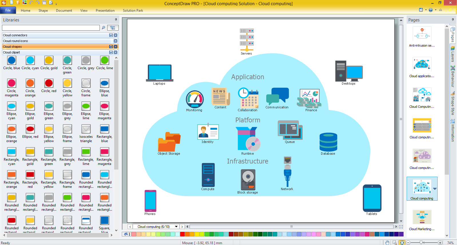
Picture: What is Cloud Computing
Related Solution:
It's no secret that there is a list of skills that every average system administrator should have. And it's important to be able to manage domains via active directory technologies. The best way to keep all the details in mind is to draw a diagram representing users, groups and domains.
This diagram represents an Active Directory Services (Active Directory Domain Services). It can be helpful for system and network administrators to organize a network physical and logical elements (domains, data bases, servers, network equipment, end-user computers etc.) into a secure and logical structure. The logical structure of Active Directory is a hierarchical organization of all network components. The data that is stored in Active Directory comes from some diverse sources. The Active Directory diagram created using ConceptDraw Active Directory Diagram solution. It shows allocating group policies and functions assigned to end users. It helps to plan, manage and maintain the certain user access scenario.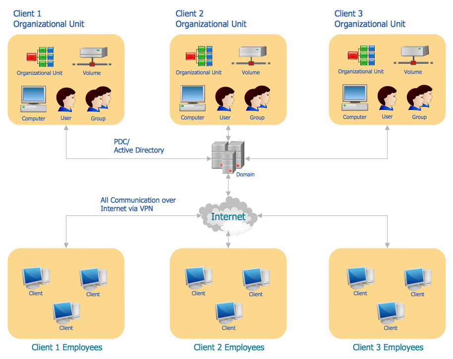
Picture: Active Directory Diagram
Related Solution:
ConceptDraw DIAGRAM is perfect for software designers and software developers who need to draw Cisco Network Diagrams.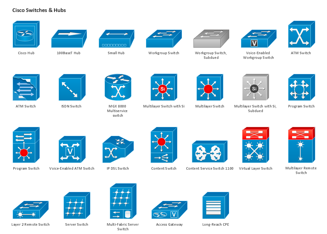
Picture: Design Element: Cisco for Network Diagrams
Creating a detailed network plan can cause a lot of headache to an unexperienced user. And it is worth mentioning that ConceptDraw DIAGRAM is a decent tool for creating a network diagram, a tool that is easy-to-use. To get an accurate diagram use the vector shapes from the special libraries that represent workstations, network appliances, wiring systems and connect them with smart-connectors, just as simple as that.
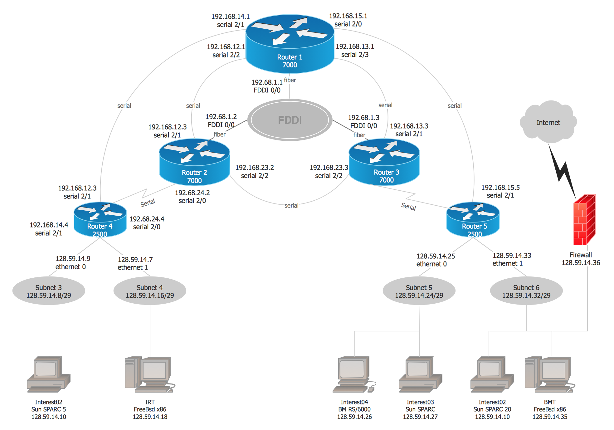
This communication network diagram displays the way different components of a computer network communicate with each other. When representing network information, such as depicting all the equipment in a large network, it is helpful to make visual representation. Network diagram provides an easy way to show the way the connections between an equipment in a large network. This diagram of a communication network depicts a network composed of three sub-networks. It uses a network equipment symbols to represent the different devices that make up a network communication including routers, Ethernet devices and end-point equipment.
Picture: ConceptDraw DIAGRAM Network Diagram Tool
Related Solution:
Nodes of any computer network are somehow organized in a hierarchy or a layout. Some of the common layouts like star network topology are more reliable and some like ring topology withstand high loads better. It is also important to distinguish logical topologies from physical.
This diagram represents a typical view of the star network topology. The star network topology is one of the most frequently used network topologies in the majority of office and home networks. It is very popular because of its low cost and the easy maintenance. The plus of the star network topology is that if one computer on the local network is downed, this means that only the failed computer can not send or receive data. The other part of the network works normally. The minus of using star network topology is that all computers are connected to a single point-switch, or hub. Thus, if this equipment goes down, the whole local network comes down.
Picture: Star Network Topology
Related Solution:
A landscape plan depicts all the features of a future garden including buildings, plants, lawns or a patio. Such plan is a very important part of site adjustment because it gives a complete picture of future project.
Picture: Landscape Plan
Related Solution:
Chemical and Process Engineering solution contains variety predesigned process flow diagram elements relating to instrumentation, containers, piping and distribution necessary for chemical engineering, and can be used to map out chemical processes or easy creating various Chemical and Process Flow Diagrams in ConceptDraw DIAGRAM.
Picture: Process Flow Diagram Symbols
Related Solution:
It is impossible to imagine mechanical engineering without drawings which represent various mechanical schemes and designs. ConceptDraw DIAGRAM diagramming and vector drawing software supplied with Mechanical Engineering solution from the Engineering area of ConceptDraw Solution Park offers the set of useful tools which make it a powerful Mechanical Drawing Software.
Picture: Mechanical Drawing Software
Related Solution:
ConceptDraw DIAGRAM diagramming and vector drawing software offers the Fault Tree Analysis Diagrams Solution from the Industrial Engineering Area of ConceptDraw Solution Park for quick and easy creating the Fault Tree Diagram of any degree of detailing.
Picture: Fault Tree Diagram
Related Solution:


