Made with
ConceptDraw
DIAGRAM 18

Interior Design. Machines and Equipment — Design Elements

Machines and equipment — Design elements library

Drawing your own plant layouts for storage, production, distribution, shipping, transport and receiving the manufactured goods is always easier with help of special software which can make your diagrams look very sophisticated and professional even if you have not much experience in creating such flowcharts.

Vector stencils library Machines and equipment contains shapes of industrial machines and equipment for drawing plant interior design plans and manufacturing equipment layouts using ConceptDraw DIAGRAM diagramming and vector drawing software.

This library is included in Plant Layout Plans solution from Building Plans area of ConceptDraw Solution Park.

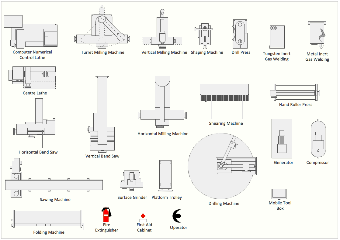
The Machines and Equipment library contains 24 symbols:

  • Computer numerical control lathe
  • Centre lathe
  • Horizontal band saw
  • Vertical band saw
  • Sawing machine
  • Turret milling machine
  • Vertical milling machine
  • Horizontal milling machine
  • Milling machine
  • Surface grinder
  • Shaping machine
  • Folding machine
  • Shearing machine
  • Hand roller press
  • Drill press
  • Drilling machine
  • Tungsten inert gas welding
  • GTAW
  • TIG welding
  • Metal inert gas welding
  • Generator
  • Compressor
  • Platform trolley
  • Mobile tool box
  • Fire extinguisher
  • Extinguisher
  • First aid cabinet
  • Operator
Machines and Equipment — Design Elements

Sample 1. Interior Design Software. Design Elements — Machines and Equipment
for macintosh and windows

Solution Building Plans from ConceptDraw Solution Park provides 3 vector stencils libraries with design elements for drawing plant layout plans.

Use ConceptDraw DIAGRAM diagramming and vector drawing software enhanced with Building Plans solution to draw your own plant layouts for production, storage, distribution, transport, shipping, and receiving of manufactured goods.

Read more about Home and Landscape design

TEN RELATED HOW TO's:
Cafe Decor is one of the most important components of cafe design. Just thanks to the cafe decor elements is created the unique warm atmosphere of the cafe which makes you come back there again and again. ConceptDraw DIAGRAM extended with Cafe and Restaurant Floor Plan solution can help you create Cafe Decor designs simply and fast.Cafe Decor *
Picture: Cafe Decor
Related Solution:
Design efficiently the technical flow charts in ConceptDraw DIAGRAM software for various fields and provide ✔️ clarity, ✔️ accuracy, ✔️ usability, ✔️ simple communication, analysis, and improvementTechnical Flow Chart Example Design in ConceptDraw DIAGRAM
Picture: Technical Flow Chart Example
Related Solution:
Cabinet is a necessary room in the house. It is very important that the cabinet was comfortable and convenient with elaborated design that dispose to the maximize productive work. The cabinet design is a reflection of the personality, habits and character traits of its owner. Floor Plans Solution provides templates, samples and wide collection of pre-designed vector stencils that allow you to create the cabinet design plans of any complexity quick, easy and effective.Cabinet Design Software *
Picture: Cabinet Design Software
Related Solution:
Successful Cafe Interior Design is so much broad definition, it includes a lot of things beginning from the choice of furniture and its placement, and finishing by the elements of design and interior, and by many other little details. ConceptDraw DIAGRAM offers the Cafe and Restaurant Floor Plan Solution from the Building Plans area allowing architects and designers develop and represent the Cafe Interior Design of any detailing.Cafe Interior Design *
Picture: Cafe Interior Design
Related Solution:
ConceptDraw DIAGRAM is a powerful electrical design software. The Electrical Engineering solution from the Engineering area of ConceptDraw Solution Park allows you easy, quick and effective draw the professional looking electrical, circuit and wiring diagrams and schemes, maintenance and repair diagrams for electronics and electrical engineering, and many other types of diagrams.Electrical Design Software *
Picture: Electrical Design Software
Related Solution:
This sample was created in ConceptDraw DIAGRAM software using the Flowcharts solution.Copying Service Process Flowchart. Flowchart Examples
Picture:
Copying Service Process Flowchart.
Flowchart Examples
Related Solution:
Local area network connects computers and other network appliances within an area, such as office building or a campus. It can be difficult to provide such network without a predesigned plan. For these purposes you can use network diagram software, which helps you to create LAN network diagrams and office network diagrams quickly and effortless. This will speed up your work and you can save the diagram for the future network improvements. The following diagram illustrates a network topology of the small office. LAN configuration has a star topology. The local network joins 8 computers among which are several desktop PCs, laptop, two iMacs and iBook. The end-point devices are divided into three groups. Each group is connected to its hub. There is a network printer and a modem, which are interconnected with other devices through a network server. Each computer on the LAN can access the server through a corresponding hub.LAN Network Diagram
Picture: Network Diagram Software. LAN Network Diagrams. Physical Office Network Diagrams
Related Solution:
A flowchart is a simple but very functional tool when it comes to understanding a workflow or to removing unnecessary stages from a process. When drawing flowcharts, keep in mind that there are four common types of flowcharts, like document flowcharts and data flowcharts that show control over a data or document flow over a system. To show controls on a physical level, use system flowcharts. In addition, to show controls in a program, you can draw a program flowchart. This flowchart diagram represents the piece of an article editing process, that involves the author and editor. It was created using the Basic Flowchart notation that consists from the basic flowchart symbols. The start and the end of the process are indicated with "Terminator" symbols. The "Process" symbols show the action steps consisting from making edits and searching for a compromise, when the author does not agree with the suggestions of the editor. The "Process" symbol is the general symbol in process flowcharts. The "Decision" symbol indicates a branching in the process flow. There are two branches indicated by a Decision shape in the current flowchart (Yes/No, Disagree/Agree). This basic flowchart can be used as a repeating unit in the workflow diagram describing the working process of some editorial office.Types of Flowcharts *
Picture: Types of Flowcharts
Related Solution:
The purchasing process follows very specific guidelines and includes a purchasing cycle flowchart and receiving process flow chart. Common key elements of purchasing process. It is important to know how purchasing processes work and how each operation is done.Purchase Process Flow Chart,<br>Receiving Process Flow Chart,<br>Accounting Flowchart Example. *
Picture: Purchase Process Flow Chart,Receiving Process Flow Chart,Accounting Flowchart Example.
Related Solution:
It is important to have an electrical circuits scheme, when you plan a renovation or move to a new apartment. You have to arrange interior according to that plan, and it’s trouble-free to create wiring diagrams with ConceptDraw DIAGRAM , furthermore, this software has all the features needed to create an interior plan as well. So, get inspired by tons of examples included to ConceptDraw DIAGRAM solutions, and start your diagramming experience! A wiring diagrams, that are represented on this drawing was created to depict the components of the electrical circuit schemes. These diagrams are created to depict the information about circuit arrangements and connections. Wiring diagrams, in contrast to physical drawings, use standard symbol's notation to depict different circuit devices and connections. That is why, wiring diagrams are applied to discover and repair electrical and electronic circuits. The vector graphic objects provided by ConceptDraw Electrical Engineering solution can help any specialist in electric engineering to design electrical schemes, circuit and wiring plans, power systems charts, and Maintenance and Repair diagrams.Wiring Diagrams with ConceptDraw DIAGRAM
Picture: Wiring Diagrams with ConceptDraw DIAGRAM
Related Solution:
ConceptDraw
DIAGRAM 18