How To Create Home Plan with Examples
Home Plan software
Once you need to create your design house plan layout in order to have renovation in or just to decorate the place you live in, it can take only a few minutes to draw the whole thing if you have ConceptDraw DIAGRAM as it is software that allows people to make any kind of diagram, chart, flowchart, scheme or plan for a very short time which make things much simpler, doesn’t it? No need to be a designer or have many years of experience in making similar layouts once you have our templates and examples which you can use as the drafts for your own plan and be happy about what will appear in a result. Make your own great looking home plan using our libraries with so many design symbols and elements, such as: stencils of windows, walls, doors, different kinds of furniture like tables, chairs, arm-chairs, beds, sofas, as well as plants, TV, bath, sink and lots of other elements.
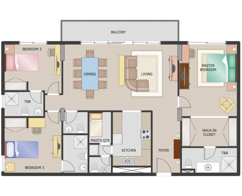
Pic 1. Home Plan
This small custom house floor plan sample is drawn using ConceptDraw DIAGRAM diagramming and vector drawing software enhanced with Building Plans Solution.

Pic 2. Building Plans Solution
The Building Plans Solution from ConceptDraw Solution Park provide samples, templates and shapes libraries for drawing the building plans, floor and site plans, blueprints, landscapes and garden layouts and designs.
TEN RELATED HOW TO's:
The PERT Chart is constructed as part of the process in creating a schedule of corrective actions. The PERT Chart shows the logical connections and consequence of tasks to be performed. It displays the time period for problem solving and the implementation of all activities through the critical path.
ConceptDraw Office suite is a software for corrective actions planning.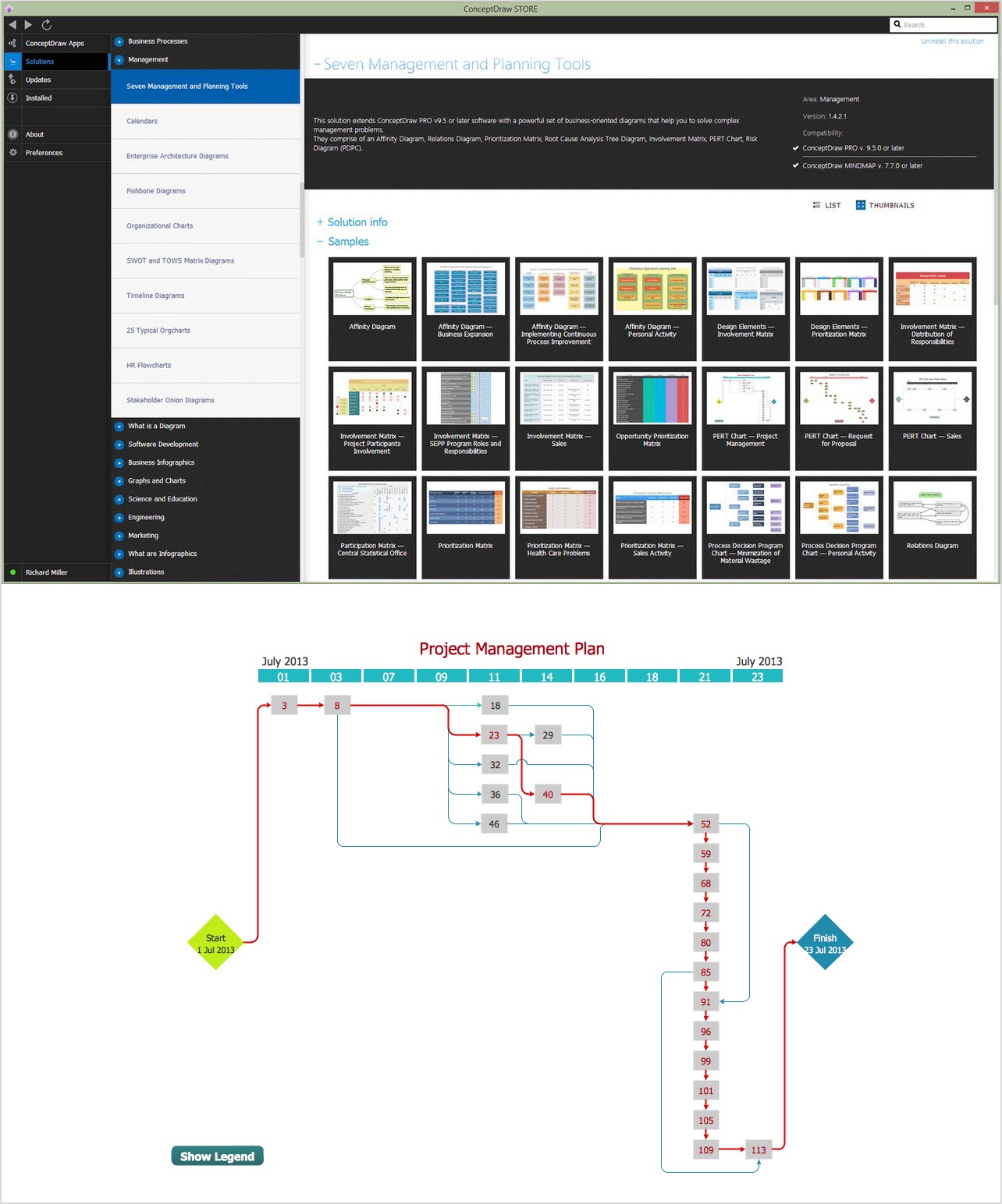
Picture: CORRECTIVE ACTIONS PLANNING. PERT Chart
A lot of business process techniques are able to be applied in regular life. Although this tool is considered to be used for business purposes, you can make a SWOT template for yourself. In fact, any obstacle might become a subject for SWOT analysis.
ConceptDraw solution for SWOT analysis solution provides a power visual maintenance of a SWOT analysis. It is a procedure of strategic planning made to discover the Strengths, Weaknesses, Opportunities, and Threats business meet. This mind map template for ConceptDraw MINDMAP isually maintains investigation of good and bad factors. For example, factors that provides an advantage over others are strength; factors that brings a disadvantage are factors of weakness. After the analysis is finished, transfer your data to create a SWOT matrix in ConceptDraw DIAGRAM.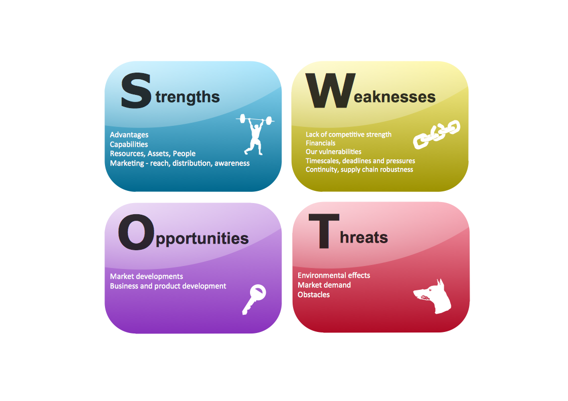
Picture: SWOT Template
Any classroom is unique for the room layout, for the location of windows and lighting, the purposes of the classes are also different, so the arrangement of chalkboard and seating places will be different and must consider all these points. ConceptDraw DIAGRAM software extended with School and Training Plans Solution from the Building Plans Area of ConceptDraw Solution Park offers you the possibility to design the Classroom Seating Charts of any complexity.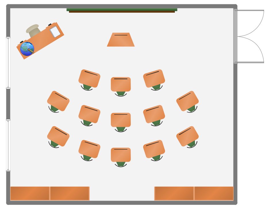
Picture: Classroom Seating Charts
Related Solution:
What is a Concept Map and what software is effective for its design? A concept map or conceptual diagram is a diagram that depicts suggested relationships between concepts. As for effective software - we suggest you to pay attention for the ConceptDraw DIAGRAM diagramming and vector drawing software. Extended with Concept Maps Solution from the Diagrams Area it is a real godsend for you.
Picture: What Is a Concept Map
Related Solution:
Once you have created your document in ConceptDraw DIAGRAM and you want to share it with your colleagues and friends, who uses MS Visio on their computers, you can easily export your document using ConceptDraw DIAGRAM export to Visio XML files (VDX) feature.
Now you can share your ConceptDraw documents with MS Visio users.
Picture: Export from ConceptDraw DIAGRAM Document to MS Visio® XML
UML Communication Diagram depicts the interactions between objects or parts in terms of sequenced messages and describes both the static structure and dynamic behavior of a system.
Picture: Diagramming Software for Design UML Communication Diagrams
The kitchen is one of the important places of the house, and so the kitchen planning is a very responsible moment. The kitchen must be comfortable, convenient, harmonious and aesthetic.
ConceptDraw DIAGRAM vector drawing software offers the Floor Plans Solution from the Building Plans area of ConceptDraw Solution Park to help you create professional looking Kitchen Plans of any complexity.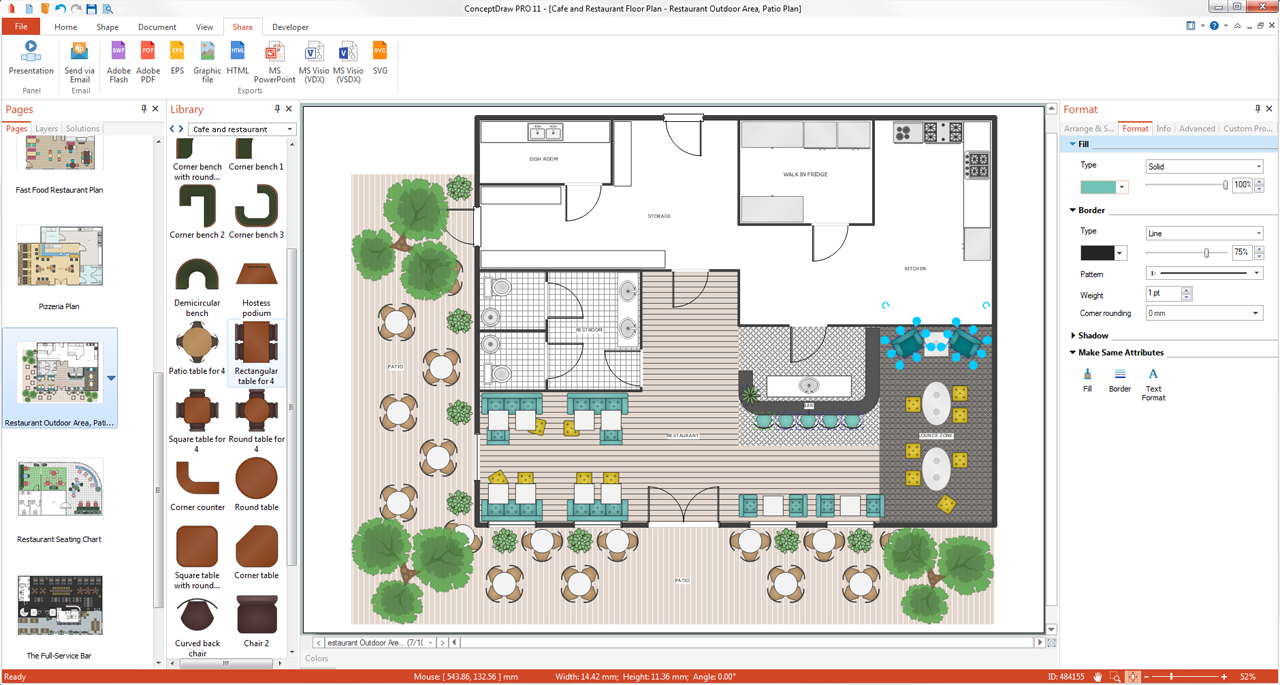
Picture: Kitchen Planning Software
Related Solution:
This sample was created in ConceptDraw DIAGRAM diagramming and vector drawing software using the UML Class Diagram library of the Rapid UML Solution from the Software Development area of ConceptDraw Solution Park.
This sample shows the structure of the building and can be used by building companies, real estate agencies, at the buying / selling of the realty.
Picture: UML Class Diagram Example - Buildings and Rooms
Related Solution:
The Office Layout Plans Solution contains a large quantity of vector objects that will make your creating of the office design plans easy, quick and effective. It also provides templates and samples that will help you create the office designs of any difficulty in one moment.
Picture: Office Design Software
Related Solution:
The ConceptDraw vector stencils library Cisco LAN contains symbols for drawing the computer local area network diagrams.
Picture: Cisco LAN. Cisco icons, shapes, stencils and symbols
Related Solution:
