
Example 1. Office Floor Plans - Office Space Plan
Look at the diversity of vector objects offered by the libraries of Office Layout Plans Solution. We are sure that it will help you design Office Floor Plans of any complexity - from large to small office layout plans or Cubicle Layout plans. Simply drag the desired of them from the libraries to the document and quickly arrange them.
Office Layout Plans Solution contains also a large set of predesigned samples available for viewing and editing from ConceptDraw STORE.

Example 2. Office Floor Plans - Cubicle Layout
The Office Floor Plans you see on this page were created in ConceptDraw DIAGRAM using the objects from the Office Layout Plans Solution libraries. These samples demonstrate the solution's capabilities and the professional results you can achieve. An experienced user spent 10 minutes creating every of them.
Use Office Layout Plans Solution for ConceptDraw DIAGRAM to make your own Office Floor Plans quick, easy, and effective.
All source documents are vector graphic documents. They are available for reviewing, modifying, or converting to a variety of formats (PDF file, MS PowerPoint, MS Visio, and many other graphic formats) from the ConceptDraw STORE. The Office Layout Plans Solution is available for all ConceptDraw DIAGRAM or later users.
TEN RELATED HOW TO's:
Unfortunately, a man can’t predict the future and no one is safe from natural disasters, such as floods, earthquakes, hurricanes or fires. Nonetheless, what you can do to ensure safety for you and your relatives is to create an emergency plan, so everyone will know what to do if emergency happens. Keep that plan simple and train it several times a year so that no one could forget any details of it.
Fire and emergency plans are important to supply people with a visual safety solution. This diagram presents a set of standard symbols used to depict fire safety, emergency, and associated information. Using clear and standard symbols on fire emergency plans provides the coherence of collective actions , helps to avoid embarrassment, and improves communications in an emergent situation. The fire emergency symbols are intended for the general emergency and fire service, as well as for building plans ,engineering drawings and insurance diagrams. They can be used during fire extinguishing and evacuation operations, as well as trainings. It includes vector symbols for emergency management mapping, emergency evacuation diagrams and plans.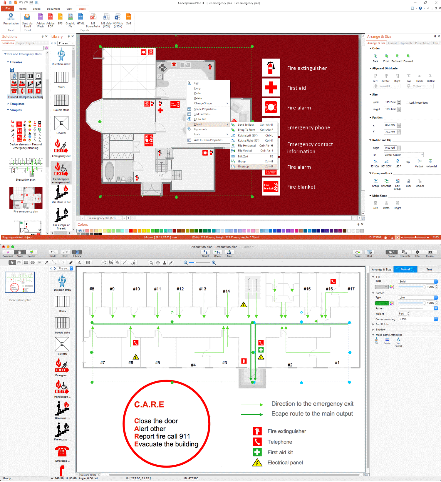
Picture: Emergency Plan
Related Solution:
ConceptDraw DIAGRAM diagramming and vector drawing software offers the Office Layout Plans Solution from the Building Plans Area of ConceptDraw Solution Park with powerful tools to help you depict your construction and design Office Ideas.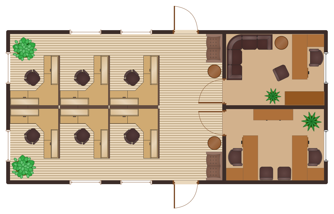
Picture: Office Ideas
Related Solution:
ConceptDraw DIAGRAM diagramming and vector drawing software is the best choice for making professional looking Emergency Plan template, examples and samples. ConceptDraw DIAGRAM provides Fire and Emergency Plans solution from the Building Plans Area of ConceptDraw Solution Park.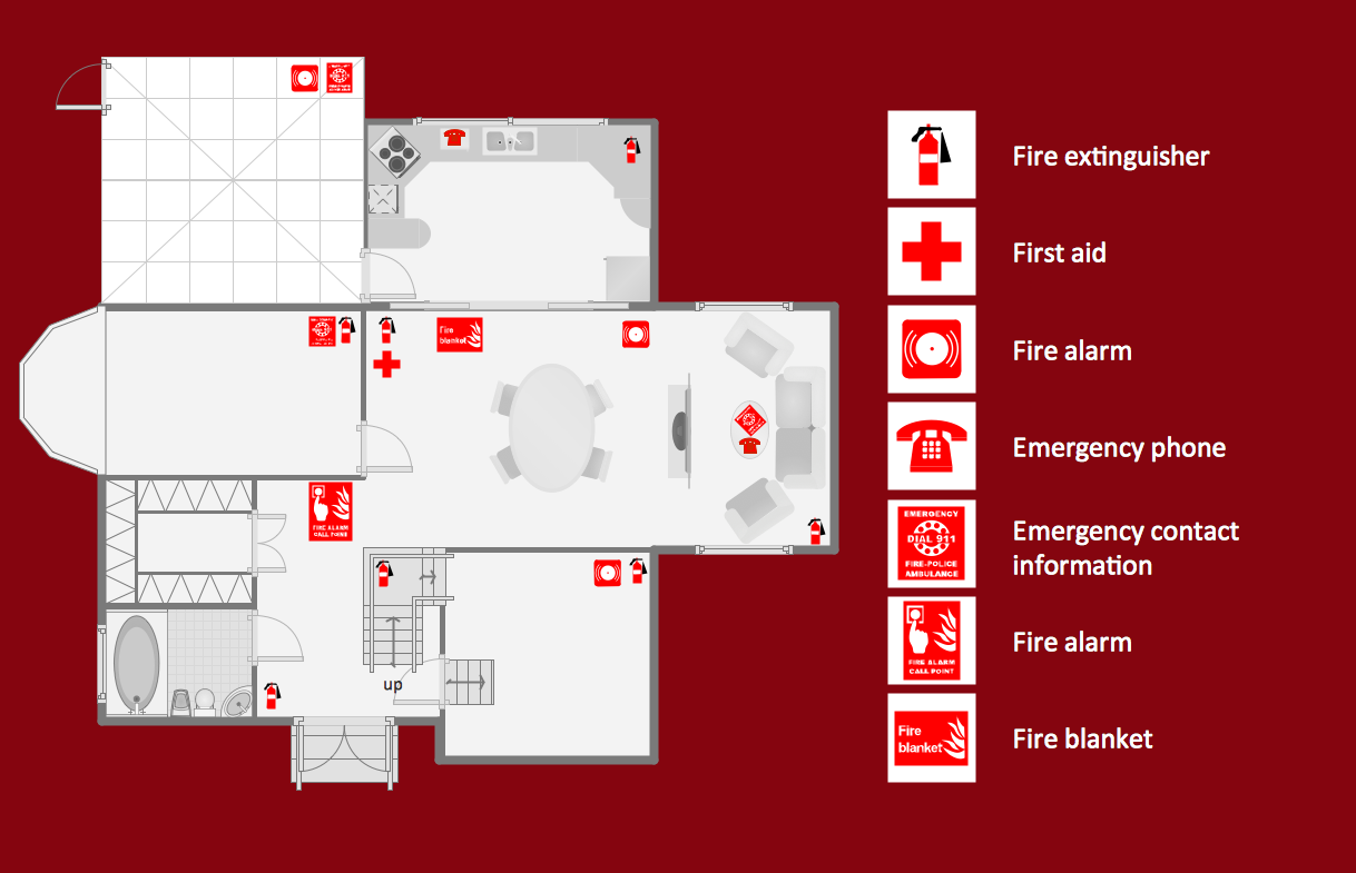
Picture: Emergency Plan Template
Related Solution:
Some organization hold offices for years and decades, or even build their own campuses. However, if it’s time for your organization to move to another building, drawing software for designing office layout plan would come in handy. With such software you can save a lot of time and create a new layout or try to save old layout in a new building.
This office layout plan is an example of a typical office furniture and equipment arrangement. This drawing provides a graphic view of the office area and its facilities including furniture and office equipment. It can be used as template which represent, desks, files, and other pieces of equipment that can be re-arranged according the certain requirements to office space and facilities. The vector graphic objects that represent various office layout elements such as special office furniture and equipment can help you to shape a number of creative ideas and develop your office layout plan.
Picture: Building Drawing Software for Design Office Layout Plan
Related Solution:
The building plans and premises layouts are obligatory for correct construction, repair and design any building, and especially office buildings. ConceptDraw DIAGRAM diagramming and vector drawing software extended with Office Layout Plans solution from the Building Plans Area of ConceptDraw Solution Park is a powerful Office Planning and Building Layout Software.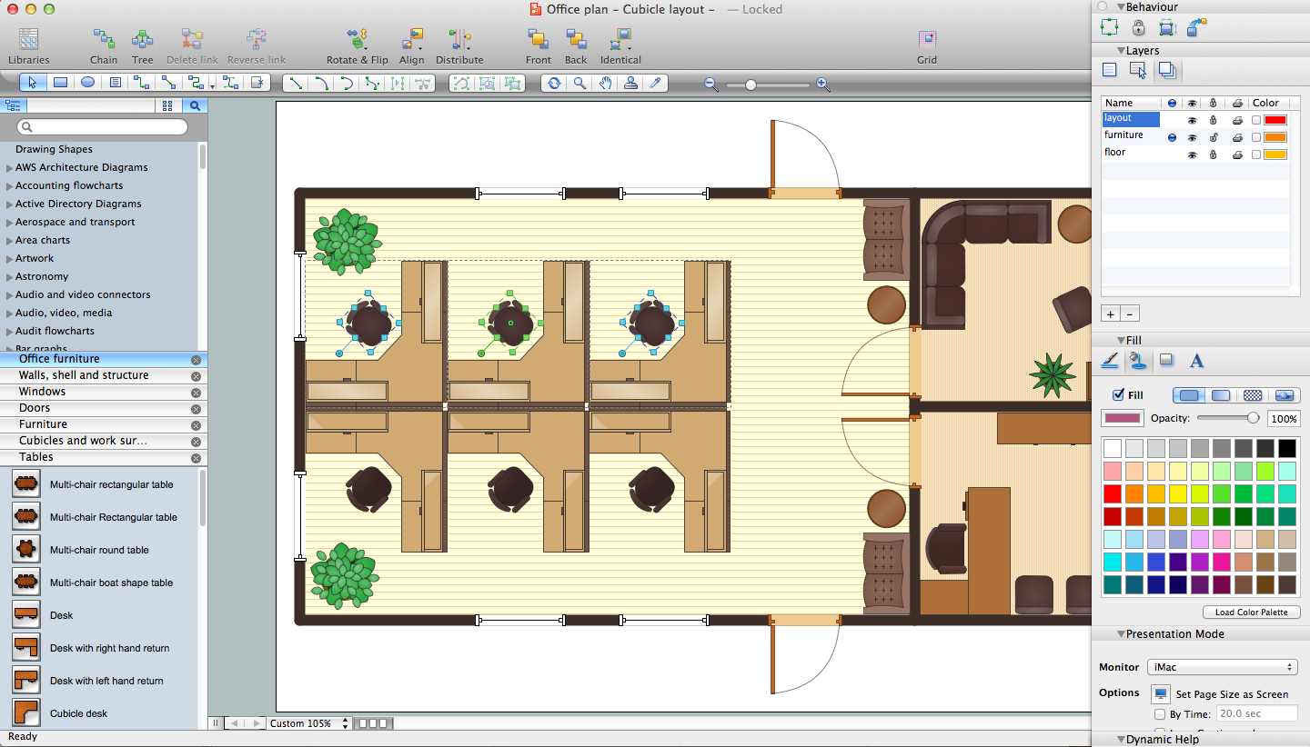
Picture: Office Planning and Building Layout Software
Related Solution:
ConceptDraw DIAGRAM extended with Floor Plans Solution from the Building Plans Area is a quick floor plan software for creating great-looking floor plans, floor charts and blueprints for facilities management, move management, office supply inventories, assets inventories, office space planning, and cubicles.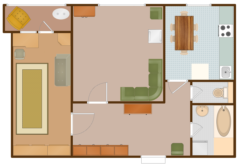
Picture: Floor Plan
Related Solution:
Nowadays, more and more attention is paid to the comfort in the workplace, so that employees might be more motivated. Thus, it can be said with full confidence that office layout plays an important role for employees and influences company reputation. Many worldwide known companies have headquarter offices resembling more of a campus than of an office building.
Every organization has its own unique office design ideas, needs and requirements. Each of office position requires a certain type of person who has his own requirements, needs and habits. Office layout should be designed to facilitate its business function. The well-organized office space plays an important role in a workflow enhancement and productivity improvement. This office layout diagram demonstrates a typical cubical office layout. This diagram can be use as a template for cubicle office layout organization. This visual example can help shape ideas and design your office layout conception. You can start with adding your requested office furniture objects into your office floor plan. Plants help to create a healthy indoor environment. You can design an office space that totally fits your needs.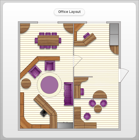
Picture: Office Layout
Related Solution:
A cozy atmosphere is crucial for the success of any cafe or restaurant. To provide it, you should use restaurant floor plan software at the stage of design. If your establishment is located conveniently and has a harmonic atmosphere inside it, this is bound to be a success.
This sample Restaurant floor plan illustrates the possibilities of ConceptDraw solution for Cafe and Restaurant plans. It represents the location of the restaurant's main hall with its furnishing as well as a plan of kitchen and toilets. Generally, Cafe and Restaurant Plans solution has a big set vector images of tables, seats, lightening, etc. Using them you will be able to plan the restaurant of your desire with an incredible design and spirit.
Picture: Restaurant Floor Plan Software
Related Solution:
Home remodeling is something that many people face at one point or the other. The first part of any home remodeling is to create a new home plan. At first, it may seem a daunting and costly endeavor, but to take it on yourself, you just need to choose the right home remodeling software. Digital drawing software, such as ConceptDraw DIAGRAM , includes home plan examples to help you get started, as well as multiple advanced and powerful options, and an intuitive interface to go with them.
People who want to make changes in their houses planning have previously prepare a plan of rebuilding, of house, apartment or any other construction. If somebody desires to change anything in the interior design he also requires a plan, as it’s handy to see on the plan the coming result and then begin to implement it. All these tasks will be solved better with ConceptDraw DIAGRAM and its solution for Building Plans. You will design professional looking Home Plans quick and easy using the vector libraries, templates and samples, supplied with Solution.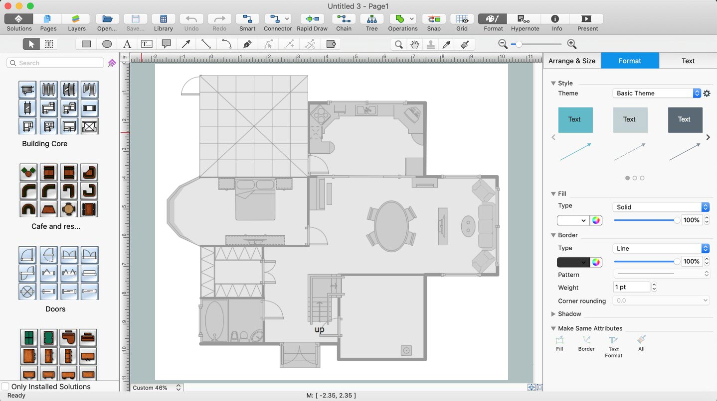
Picture: Home Remodeling Software. Home Plan Examples
Related Solution:
There are numerous articles about the advantages of flowcharting, creating business graphics and developing different charts. Nevertheless, these articles are almost useless without the main component - the examples of flowcharts, org charts and without a fine example, it is difficult to get all the conveniences of creating diagrams. You can find tons of templates and vivid examples on Solution Park.
This illustration shows a variety of business diagrams that can be created using ConceptDraw DIAGRAM. It comprises a different fields of business activities: management, marketing, networking, software and database development along with design of infographics and business illustrations. ConceptDraw DIAGRAM provides a huge set of sample drawings including business process modeling diagrams,, network diagrams, UML diagrams, orgcharts, DFD, flowcharts, ERD, geographical maps and more.
Picture: Examples of Flowcharts, Org Charts and More
Related Solution:


