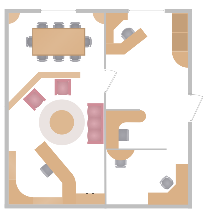
Example 1. Small Office Design
Office Layout Plans Solution provides collection of samples with variety of ideas for small office design and large offices designs. All samples are grouped and available from ConceptDraw STORE.

Example 2. Office Layout Plans Solution in ConceptDraw STORE
ConceptDraw DIAGRAM offers you the possibility to create office floor plans, office design plans, furniture layout plans, and also many other plans for the office electricity and water supplying, lighting, wireless network, etc. Use actively the objects from the libraries of Office Layout Plans Solution and other solutions from the Building Plans Area.

Example 3. Office Wireless Network Plan
The samples you see on this page were created in ConceptDraw DIAGRAM using the tools of Office Layout Plans solution from the Building Plans area. These samples demonstrate a few variants of Small Office Design. An experienced user spent 5-10 minutes creating every of these samples.
Use Office Layout Plans Solution for ConceptDraw DIAGRAM to make your own Small Office Design Plan quick, easy, and effective.
All source documents are vector graphic documents. They are available for reviewing, modifying, or converting to a variety of formats (PDF file, MS PowerPoint, MS Visio, and many other graphic formats) from the ConceptDraw STORE. The Office Layout Plans Solution is available for all ConceptDraw DIAGRAM or later users.
TEN RELATED HOW TO's:
Unified Modeling Language (UML) is a graphical modeling language for describing, visualizing, projecting and documenting of object oriented systems. UML digram is used for modeling of organizations and their business processes, for development the big projects, the complex software applications. Comprehensive UML diagram allows to create the set of interrelated documents that gives the complete visual representation of the modeling system.
Picture: UML Sample Project
Related Solution:
You need create Reflective Ceiling Plan? What can be easier with ConceptDraw DIAGRAM diagramming and vector drawing software extended with Reflected Ceiling Plans Solution from the Building Plans Area.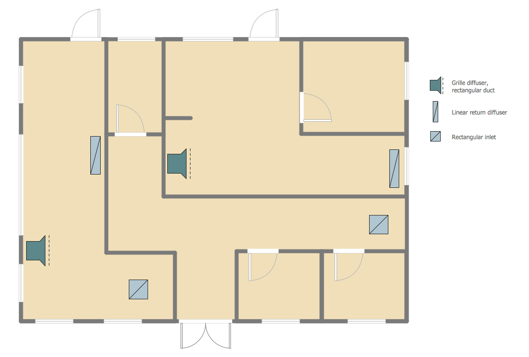
Picture: Reflective Ceiling Plan
Related Solution:
How to create a Residential Electric Plan quick and easy? The simplest way is to use the tools of ConceptDraw DIAGRAM software extended with Electric and Telecom Plans Solution.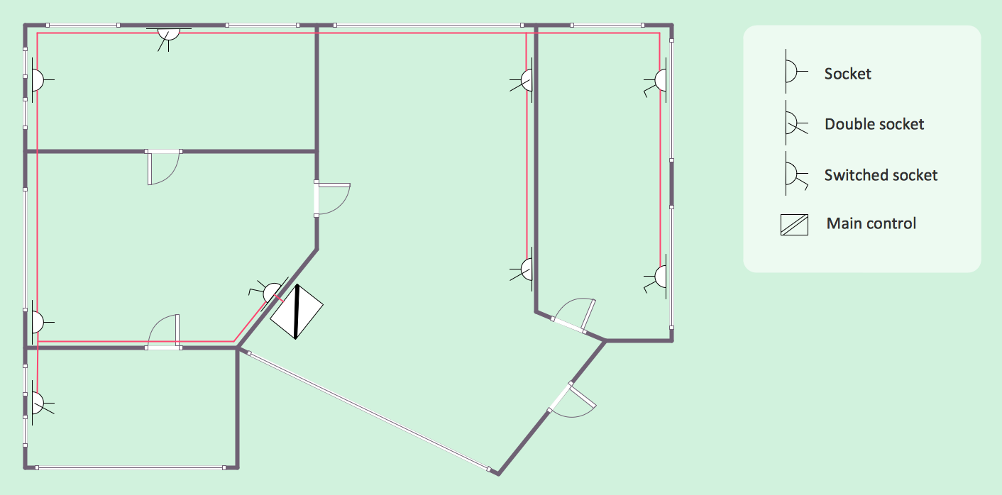
Picture: Residential Electric Plan
Related Solution:
ConceptDraw DIAGRAM enhanced with Audio, Video, Media solution is a helpful tool for illustration of a CCTV network. It contains library of vector cliparts of video and TV devices and different digital gadgets for drawing such illustrations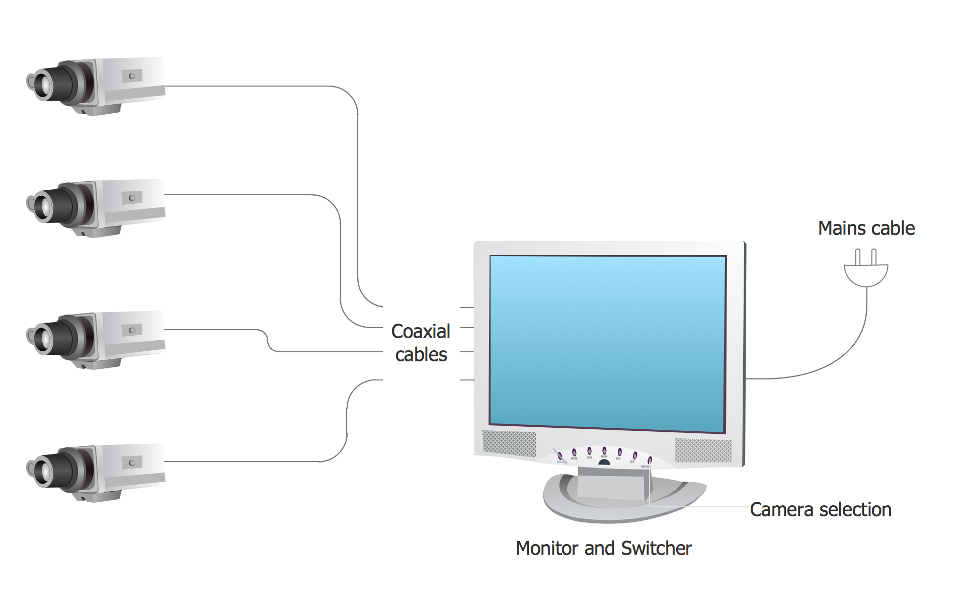
Picture: Basic CCTV System Diagram. CCTV Network Diagram Example
Related Solutions:
Outdoor activities are a very important part of leisure. Although standard basketball court dimensions are strict, you can do something to set a court even in your yard. With ConceptDraw DIAGRAM you can develop a plan to see how a basketball court is going to fit in your yard.
The favorite method of basketball coaches is visualization. For learning, for disassembly of played matches or for planning the strategy of the coming games - they always use a picture of basketball courts. Such schematically picture should have scale and should depict precisely standard equipment and dimensions of the basketball court. The Basketball solution for ConceptDraw DIAGRAM was developed as a tool for drawing different basketball schemes and illustrations.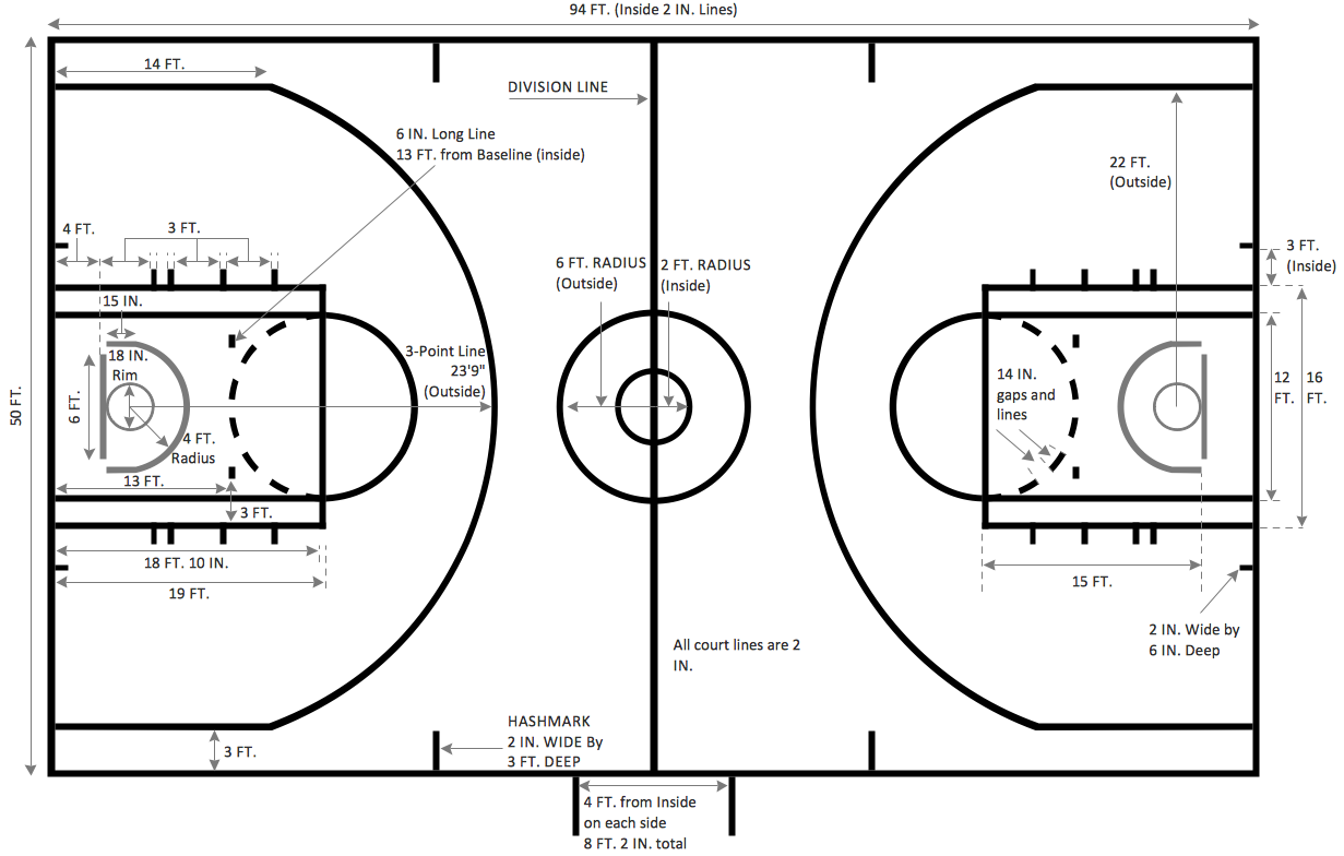
Picture: Basketball Court Dimensions
Related Solution:
ConceptDraw Solution Park creates a single information space for messaging to teams. PM Teams provides project participants and organizations with better tools that assist in task understanding, timeframe understanding, and project events in the entire organization. Improved communication fosters positive team spirit throughout.
Picture: Org Chart Diagram
Related Solution:
The arrangement of tables and seating charts near them have great value in many premises and situations. It is often very convenient to draw a plan before the furniture arrangement. ConceptDraw DIAGRAM software offers the Seating Plans solution from the Building Plans area for fast and easy drawing the table seating chart template and samples.
Picture: Table Seating Chart Template
Related Solution:
ConceptDraw DIAGRAM diagramming and vector drawing software extended with Gym and Spa Area Plans solution from Building Plans area of ConceptDraw Solution Park is the best for simple and fast drawing the Fitness Plans.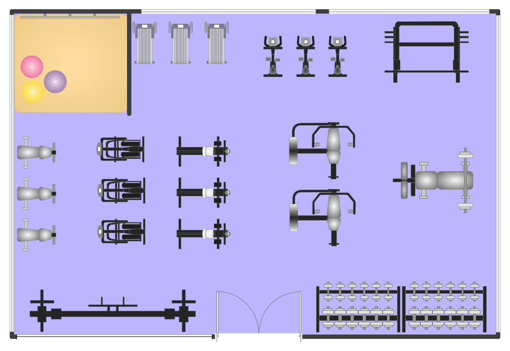
Picture: Fitness Plans
Related Solution:
ConceptDraw DIAGRAM extended with Network Layout Floor Plans Solution from the Computer and Networks Area is a powerful home networking software. Use it to design your own professional looking home network diagrams without efforts.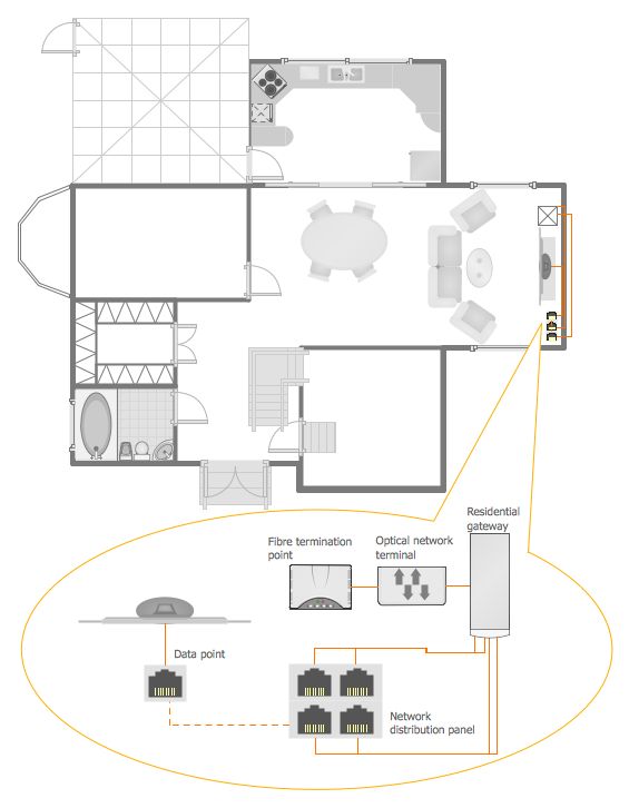
Picture: Home Networking
Related Solution:
If you have a premise, or a studio and you want to start your own business, catering might be perfect for you. You can see a cafe floor plan as an example of possible usages of the free space on the floor. Obviously, you can rearrange it in any plausible way.
This cafe floor plan was created with a help of ConceptDraw solution for Cafe and Restaurant Floor Plans. Working under the design of interiors plans for cafe, commonly cause various creative and architectural issues. Primarily, cafe floor plan and interior design must be nice and at the same time comfortable for customers. Developing a floor plan and interior conception for cafe involve various elements that can be found out in the ConceptDraw Cafe and Restaurant Floor Plan solution. This sample drawing may be used as a template while proceeding to design a particular cafe. This sample plan can help to select furniture most suitable for cafe's guest rooms or cuisine. Also, this drawing may be handy as a requirements list of a furnishing and accessories necessary for the new cafe.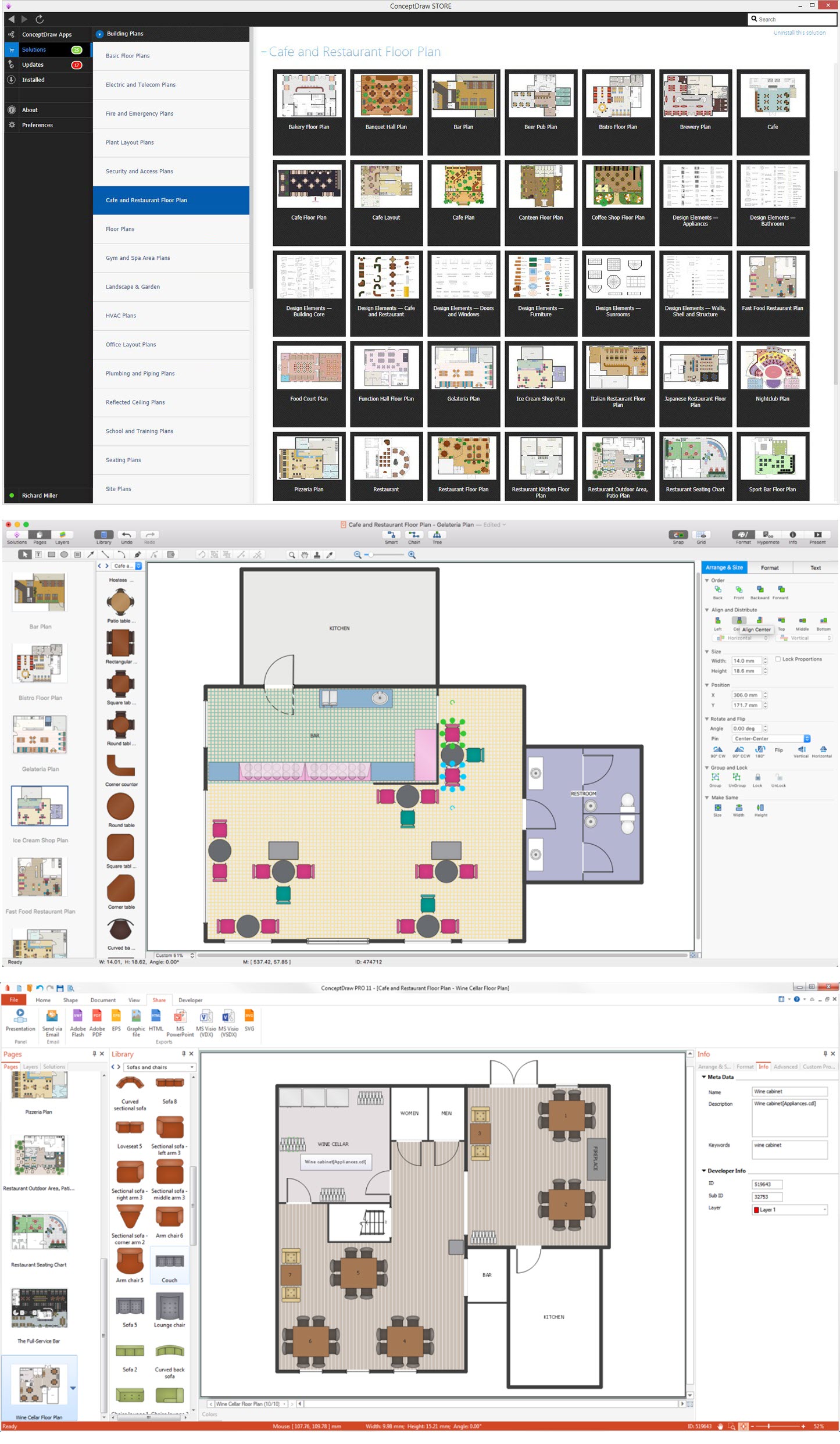
Picture: Café Floor Plan Example
Related Solution:

