Building Drawing. Design Element Site Plan
Making some site plan in order to describe its interior and the general looking of something your want to draw or create, you need pre-made by designers building drawing elements so your final result looks very professional and smart. People who work with creating such plans are usually designers themselves or at least architects, but you do not need to have any of previous experience in making such design plans and schemes if you have ConceptDraw DIAGRAM software which allows you to make any of needed plan, scheme as well as to draw any diagram, chart or flowchart very quick (for a couple of minutes) using lots of pre-made symbols and design elements which all are in the stencil libraries available for each of our users with no limits: you can find any library you need depending on the subject and take all necessary elements out of it to ensure yourself that the final scheme looks smart and very professional as well as sophisticated.
ConceptDraw has 1493 vector stencils in the 49 libraries that helps you to start using software for designing Site Plan. You can use the appropriate stencils from Site Accessories library with 18 objects and Parking, Roads library with 18 objects, Trees and Plants library with 29 objects.
- Parking and Roads - A parking space is a location that is designated for parking, either paved or unpaved. Parking spaces can be in a parking garage, in a parking lot or on a city street. It is usually designated by a white-paint-on-tar rectangle indicated by three lines at the top, left and right of the designated area. The automobile fits inside the space, either by parallel parking, perpendicular parking or angled parking.
Contains parking lots and strips, parking spaces, driveways, street junctions, and interchanges for parking facilities, on-street parking, and traffic management. Use residential and commercial landscape design, parks planning, yard layouts, plat maps, outdoor recreational facilities, and irrigation systems.
- Site Accessories - A site plan is an architectural plan, landscape architecture document, and a detailed engineering drawing of proposed improvements to a given lot. A site plan usually shows a building footprint, travelways, parking, drainage facilities, sanitary sewer lines, water lines, trails, lighting, and landscaping and garden elements.
Contains vehicle access control equipment (tollbooth, tollgate, parking fees payment box), a handicapped sign, outdoor lighting, and garbage receptacles for parking lots and site management. Use for residential and commercial landscape design, parks planning, yard layouts, plat maps, outdoor recreational facilities, and irrigation systems.
- Trees and Plants - Landscape design is an independent profession and a design and art tradition, practised by landscape designers, combining nature and culture. In contemporary practice landscape design bridges between landscape architecture and garden design. Landscape design focuses on both the integrated master landscape planning of a property and the specific garden design of landscape elements and plants within it.

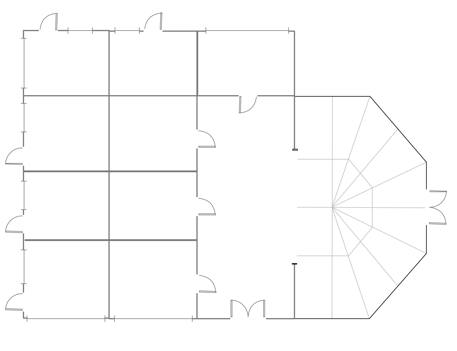
Example 1. Design Elements — Site Plan for Building Drawing
Solution Building Plans from ConceptDraw Solution Park provides vector stencils libraries with design elements for drawing Site Plans.

Example 2. Site Plan Examples
Use ConceptDraw DIAGRAM diagramming and vector drawing software enhanced with Building Plans solution to draw your own residential and commercial landscape design, parks planning, yard layouts, plat maps, outdoor recreational facilities, and irrigation systems.
TEN RELATED HOW TO's:
Database structures are usually described by ER-diagrams which represents entities as boxes with lines-connections between them. You can create any entity-relationship diagram (ERD) by means of ConceptDraw DIAGRAM using ready-to-use templates and special libraries containing all the needed symbols and shapes. Creating a model for your database from now on can take just a few minutes.
ERD (entity relationship diagram) designed to show the logical structure of databases. It intended to depict the relationships between data components (entities). ERDs are a popular tool for software engineers and architects. Using ERD they can manage the every aspect of database design. Also ERD can be used as guidelines for testing and communications before software release. This diagram represents the file reference system of the WordPress web platform. Because entity relationship diagrams have such a broad application area through the prevalence of database technology, it can be applied for a wide range of users.
Picture: Entity-Relationship Diagram (ERD) with ConceptDraw DIAGRAM
Related Solution:
Create flowcharts, organizational charts, bar charts, line graphs, and more with ConceptDraw DIAGRAM.
Picture: Basic Diagramming
Related Solution:
Network infrastructure planning is a very important process in the network construction, and the share of time allocated to this within the scope of the entire project may reach 60-80%. A competent and thorough approach to planning contributes to the quick investment return, and also increases the reliability and flexibility of the final system, reducing the probability of additional costs related to the incorrect implementation.
Any planning begins with an analysis of the business requirements to the final system. Basic network parameters, which should be assessed are the scalability, accessibility, cost, speed and safety.
Speed and cost are often mistaken for the most important parameters, and the rest of the parameters aren't even remembered. This is not entirely correct. Initially, it is necessary to assess the business plans for the future, because sometimes it is more profitable to invest more money in the beginning. If the business is to develop, then, consequently, demands on
Picture: Cisco Routers. Cisco icons, shapes, stencils and symbols
Related Solution:
Samples, templates and libraries contain vector clip art for drawing the Road Transport Illustrations.
Picture: Road Transport - Design Elements
Related Solution:
When deciding to start your own business, you have to take into account a bunch of different aspects. One of the ways to get inspired is to look through various restaurant floor plans samples or interior photos of already known establishments. This will help you, but keep in mind that a really unforgettable establishment must be unique.
This restaurant floor plan diagram was designed using ConceptDraw Cafe and Restaurant Floor Plan solution. It can be used as a sample while considering a custom restaurant design. With the help of this example you can estimate the amount of furniture best for a dining room or kitchen of the restaurant. In addition, this plan would be useful as a check list when you will consider a list of the furniture and equipment needed for all areas of the future restaurant.
Picture: Restaurant Floor Plans Samples
Related Solution:
ConceptDraw DIAGRAM contains spatial infographics samples, map templates to be filled in, and libraries of vector stencils for main design elements of spatial infographics.
Picture: Brilliant Examples of Infographics Map, Transport, Road
The ConceptDraw Home Design Software extended with Floor Plans solution from the Building Plans area of ConceptDraw Solution Park offers the powerful tools which will help you in easy developing vivid and professional-looking: Building plans, Home plans, House designs, Floor plans, Home interior designs, Furniture and equipment layouts.
Picture: Home Design Software
Related Solution:
But it never matters which hotel plan you want to illustrate in a way of a floor plan, you can always do it with ConceptDraw DIAGRAM especially it can be simple to do having the “Floor Plans” solution, which can be downloaded from the Building Plans area of ConceptDraw Solution Park.
Picture: Mini Hotel Floor Plan. Floor Plan Examples
Related Solution:
It is impossible to imagine mechanical engineering without drawings which represent various mechanical schemes and designs. ConceptDraw DIAGRAM diagramming and vector drawing software supplied with Mechanical Engineering solution from the Engineering area of ConceptDraw Solution Park offers the set of useful tools which make it a powerful Mechanical Drawing Software.
Picture: Mechanical Drawing Software
Related Solution:
When talking about engineering, one should define all the terms used, so anybody could understand the topic. Typical network glossary contains definitions of numerous network appliances, types of networks and cable systems. The understanding of basic is crucial for server management, network administration and investigating problems.
The network glossary defines terms related to networking and communications. The most of glossary items has their visual representation in ConceptDraw DIAGRAM libraries of the Computer Network Diagrams solution. This illustration presents a local area network (LAN) diagram. It designed to show the way the interaction of network devices in a local network. The diagram uses a library containing symbols of network equipment, connections and the end-point devices such as network printer, hubs, server, modem and finally computers (PC, mac, laptop). This diagram depicts a physical LAN topology.
Picture: Network Glossary Definition
Related Solution: