Made with
ConceptDraw
DIAGRAM 17

Audio Connectors

Audio connectors are simply the electrical connectors used for carrying the audio signal. Audio interfaces have certain physical parameters as well as interpretation of the signals, having the physical layer, data link layer, as well as partly the application layer. The physical characteristics of the electrical equipment include both types and numbers of the wires which are required, as well as voltages, optical intensity, frequencies and design of the connectors themselves. Any of the data link layers details can define the way some application data is encapsulated.

The application layer details are used for defining the actual audio format which is being transmitted, incorporating such codecs as MPEG-2, PCM or the DTS Coherent Acoustics codec. Sometimes the application layer is left open and some of the types of connectors are used by different hardware interfaces, meaning that in some cases not all of the components which have physically compatible connectors can actually work together.

Some of the mentioned connectors as well as other types of connectors are also used at the radio frequency for being able to connect a radio receiver to antenna. There is an analog to radio frequency connectors, which is an A/V connector – the one, known to be using the shielded cables for inhibiting the radio frequency interference as well as noise.

For both simplicity and efficiency, the signal convention can be used by the storage medium and some of the playback devices can re-encode audio so that the format, which was originally used for storage, does not have to be identical to the one, which was transmitted over the A/V interface.

Some of the connectors can carry both video as well as audio signals at the same time. The example of such devices can be HDMI combining the DVI-compliant uncompressed video data with uncompressed or compressed audio, as well as the one supporting other protocols. The so-called “FireWire” is the one used on Camcorders. Another — Digital Media Port — is simply a connector, which was proposed by Sony on its video as well as audio products. The “DisplayPort” is well known for caring both digital video as well as audio and auxiliary information.

Such device as “Mini DisplayPort” is known to be simply a smaller form factor of the display port, performing the very same function. There are also Thunderbolt, Unified Display Interface, Mobile High-Definition Link, “F-connectors” (used with RF modulators), SCART (the most common in Europe nowadays), TRS phone connectors, which have more than only one ring, and Sony's hybrid RCA with a TRS pin. The Coaxial cable also has other names, such as RG-6, RG-59, Cable television, CATV, etc.

The other composite connectors that carry audio, video, USB and power and their examples can be Apple Display Connector, Apple 30-pin dock connector used as a docking cradle for iPhone, iPad and Apple iPod, Portable Digital Media Interface, which is known to be including DisplayPort for digital audio and video, and USB-C, including DisplayPort, Thunderbolt, USB 3.1, superMHL, power and HDMI.

Nowadays there is no difference in the signals transmitted over coaxial or optical S/PDIF connectors, as both of them can carry exactly the same information. Choosing one over the other depends mainly on the availability of the appropriate connectors on the particular equipment. It also always depends on the convenience and preference of the user. Connections, which are longer than 6 meters as well as those requiring the tight bends should use the so-called “coaxial cable” because the high light signal attenuation of TOSLINK cables can limit their effective range.

The electrical connectors designed and used for audio frequencies and known to be called as the audio connectors can be either analog or digital. Most common audio connectors include single-conductor connectors, multi-conductor connectors, and digital audio interconnects as well as interfaces. Any electrical connector is known to be an electro-mechanical device, which is widely used for joining the electrical terminations as well as creating an electrical circuit. The electrical connectors are known to be consisting of plugs as well as jacks, allowing the connection to be temporary or serving as a permanent electrical joint between two different devices. Any adapter can be used for bringing together the dissimilar connectors in an effective way.

Hundreds of different types of electrical connectors are known to be manufactured for signal, power and control applications. The connectors are known to be able to join two lengths of the flexible copper cable or to connect such cable to some electrical terminal. In computing, any electrical connector can also be called as a physical interface and any ConceptDraw DIAGRAM user can represent the connections within the scheme of the electrical circuit with the help of Audio and Video Connectors Solution, available for being downloaded from ConceptDraw STORE application as the one developed especially for the purpose of enabling all the ConceptDraw DIAGRAM users to create their professionally looking schematics quickly and much simpler than doing it all from a scratch.

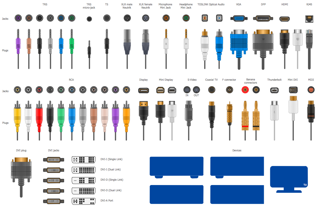
Audio Connectors *

Example 1. Audio Connectors

Audio and Video Connectors Solution offers the Audio and Video Connectors library with wide variety of predesigned objects of audio connectors and video connectors. All these objects are vector, so they can be used as is or resized without loss a quality.

Audio and Video Connectors Library Design Elements

Example 2. Audio and Video Connectors Library Design Elements

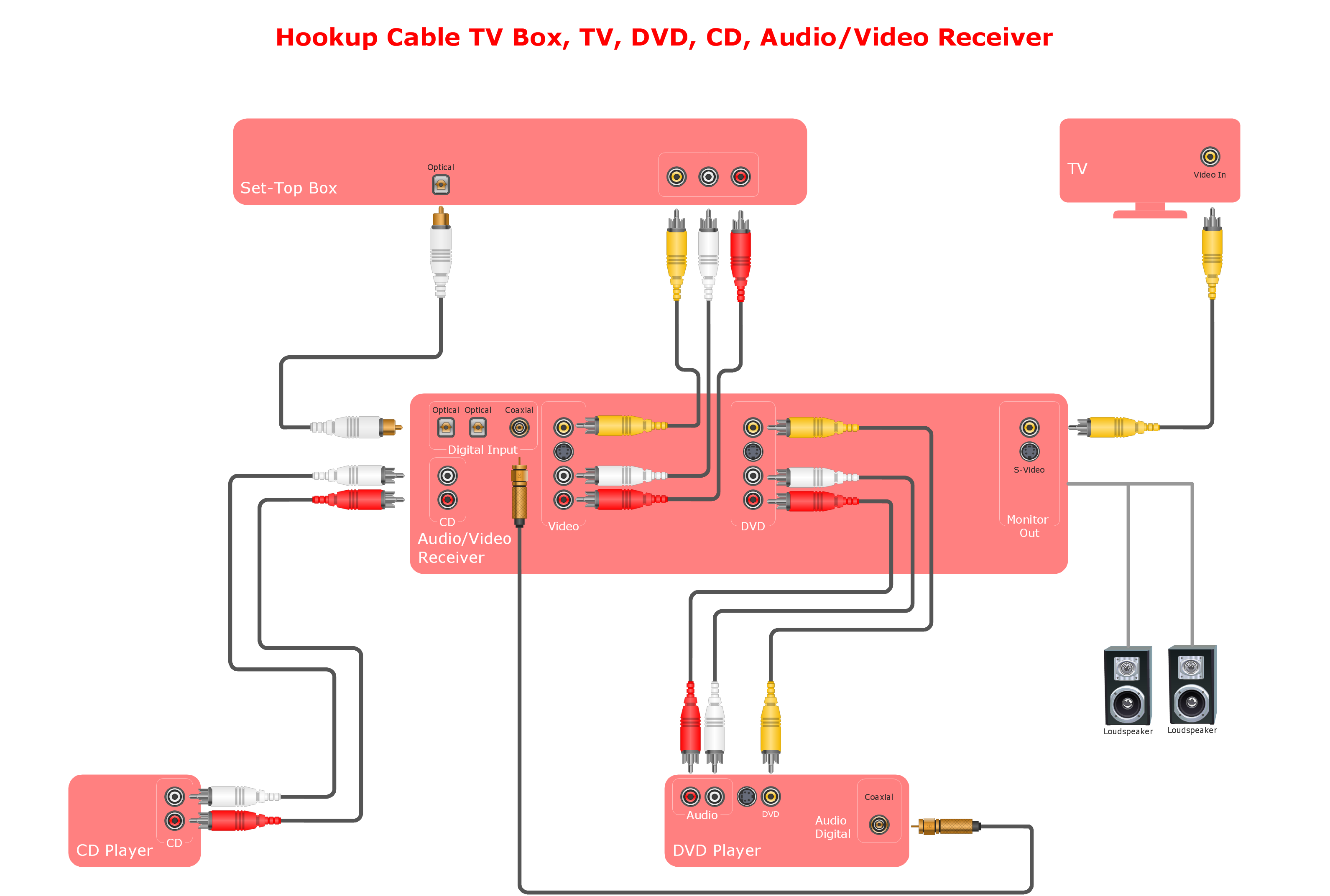
Audio and Video Connectors Solution includes also variety of ready samples which can be used as examples or as the base for your own drawings and schemes.

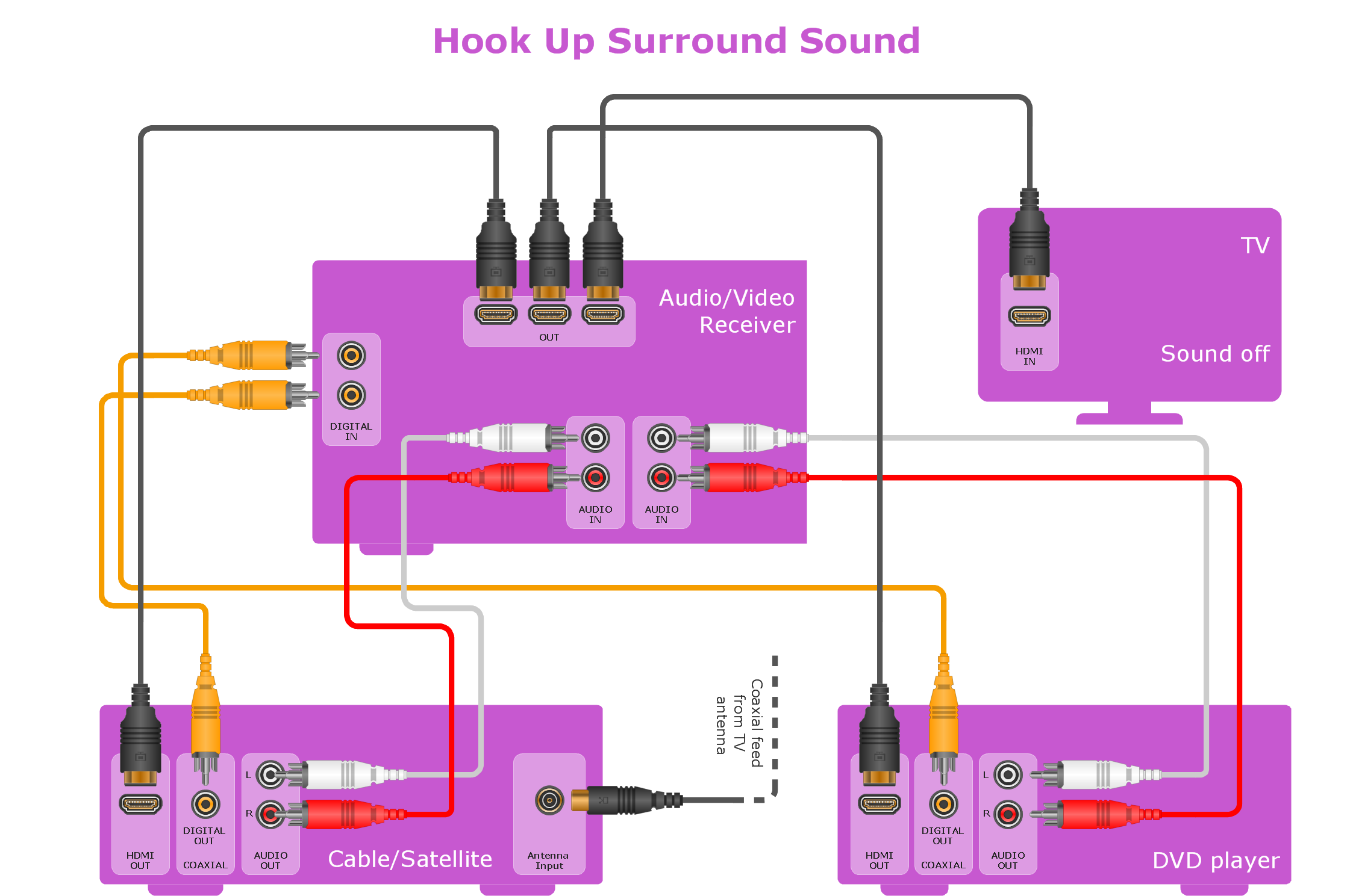
Home Entertainment System with Surround Sound

Example 3. Home Entertainment System with Surround Sound

Having the already created design elements is always much simpler rather than to make those symbols yourself from a scratch, spending lots of time on doing what was already done by the specialists of CS Odessa in order to help all ConceptDraw DIAGRAM users with their work of creating the needed schematics and diagrams. 88 vector shapes from the stencil library from the mentioned solution can all be used by any ConceptDraw DIAGRAM user so it helps make the audio or video related diagram within only a few minutes, up to an hour. Having the pre-design tools such as the mentioned design elements and symbols as well as the pre-made templates of the audio and video related diagrams can simplify the work of making similar drawings by editing the existing ones and so adding the needed symbols.


TEN RELATED HOW TO's:
The reliability is a cornerstone for any corporate computer network. If you want to provide a high fault tolerance, a mesh network topology would be the solution. The main advantage of this network is that every node can work as a commutator, although it’s not easy to set up this kind of network. A mesh network topology may be full, or partial. Full mesh network means that each node of the network (computer, workstation or other equipment) is connected directly to each of the other nodes. A partial mesh topology means that a part of nodes are connected with a whole network, and the other part of nodes are only connected to those equipment, they exchange the majority of data. This illustration shows schematic diagram of a partial mesh network containing six nodes. Each node is represented as a circles and connections are drawn as straight lines. The connections may be both wired and wireless. This scheme can be used to make the specific logical or physical network diagrams by means the ConceptDraw Computer and Networks solution.Mesh Network Topology Diagram *
Picture: Mesh Network Topology Diagram
Related Solution:
The Audio & Video Connectors solution contains a set of pre-designed objects, libraries, templates, and samples; allowing quick and easy diagramming of various configurations of audio and video devices.Standard Universal Audio & Video Connection Types *
Picture: Standard Universal Audio & Video Connection Types
Related Solution:
The Audio & Video Connectors solution contains a set of pre-designed objects, libraries, templates, and samples; allowing quick and easy diagramming of various configurations of audio and video devices.Audio Visual Connectors Types
Picture: Audio Visual Connectors Types
Related Solution:
A Storage area network (SAN) is a dedicated network that provides access to data storage and operations only on the block level. SAN usually has own network of storage devices/elements and disk arrays that are connected with each other and to a remote data-sharing network. SANs are widely used for enhancing the storage devices (optical jukeboxes, disk arrays, tape libraries) that are accessible for networked servers. This example was created in ConceptDraw DIAGRAM using the Computer and Networks Area of ConceptDraw Solution Park. It shows the hybrid of Storage area network (SAN) and Network Attached Storage (NAS) technologies.Storage area networks (SAN). <br>Computer and Network Examples *
Picture: Storage area networks (SAN). Computer and Network Examples
Related Solution:
The Audio & Video Connectors solution contains a set of pre-designed objects, libraries, templates, and samples; allowing quick and easy diagramming of various configurations of audio and video devices.Audio and Video Interfaces and Connectors *
Picture: Audio and Video Interfaces and Connectors
Related Solution:
The CCTV is the process that carried out using the video cameras for transmitting the signal to the specific location, on the limited set of monitors. We are talking about the video cameras that are used for monitoring on such guarded objects as airports, banks, stores, military objects, etc. CCTV equipment is also used in the industrial installations, for surveillance in the public places, for recording the video on the digital video recorders.CCTV Network Diagram Software *
Picture: CCTV Network Diagram Software
Related Solutions:
It is important to have an electrical circuits scheme, when you plan a renovation or move to a new apartment. You have to arrange interior according to that plan, and it’s trouble-free to create wiring diagrams with ConceptDraw DIAGRAM , furthermore, this software has all the features needed to create an interior plan as well. So, get inspired by tons of examples included to ConceptDraw DIAGRAM solutions, and start your diagramming experience! A wiring diagrams, that are represented on this drawing was created to depict the components of the electrical circuit schemes. These diagrams are created to depict the information about circuit arrangements and connections. Wiring diagrams, in contrast to physical drawings, use standard symbol's notation to depict different circuit devices and connections. That is why, wiring diagrams are applied to discover and repair electrical and electronic circuits. The vector graphic objects provided by ConceptDraw Electrical Engineering solution can help any specialist in electric engineering to design electrical schemes, circuit and wiring plans, power systems charts, and Maintenance and Repair diagrams.Wiring Diagrams with ConceptDraw DIAGRAM
Picture: Wiring Diagrams with ConceptDraw DIAGRAM
Related Solution:
In electrical engineering, a switch is an electrical component that can break an electrical circuit, interrupting the current or diverting it from one conductor to another. The mechanism of a switch may be operated directly by a human operator to control a circuit (for example, a light switch or a keyboard button), may be operated by a moving object such as a door-operated switch, or may be operated by some sensing element for pressure, temperature or flow. A relay is a switch that is operated by electricity. Switches are made to handle a wide range of voltages and currents; very large switches may be used to isolate high-voltage circuits in electrical substations. 26 libraries of the Electrical Engineering Solution of ConceptDraw DIAGRAM make your electrical diagramming simple, efficient, and effective. You can simply and quickly drop the ready-to-use objects from libraries into your document to create the electrical diagram.Electrical Symbols — Switches and Relays *
Picture: Electrical Symbols — Switches and Relays
Related Solution:
ConceptDraw DIAGRAM diagramming and vector drawing software extended with Electrical Engineering Solution from the Industrial Engineering Area of ConceptDraw Solution Park affords you the easiest and fastest way for designing professional looking Electrical Schematics.Electrical Schematics *
Picture: Electrical Schematics
Related Solution:
In general, you can use any icons to represent network equipment on a diagram. However, there are some icons, for instance, Cisco icons, shapes, stencils and symbols, that are recognizable worldwide. Using those icons you can create Cisco network topology diagrams in minutes and share them anywhere. The icons depicting Cisco network equipment are recognized and generally applied as standard images for designing network diagrams. They are free to used , but can not be reworked. Cisco network diagrams are created to depict how signals processed on the network equipment and end-user computers and how data transfer through LAN or WLAN between nodes. The vector graphic library of ConceptDraw CISCO Network Diagrams solution includes about 90 icons of Cisco network equipment for designing computer network diagrams with ConceptDraw DIAGRAM.Cisco Network Topology. <br>Cisco icons, shapes, stencils and symbols *
Picture: Cisco Network Topology. Cisco icons, shapes, stencils and symbols
Related Solution:
ConceptDraw
DIAGRAM 17