How To Print Audio & Video Connectors Schema in a Large Format
Use ConceptDraw DIAGRAM software with numerous vector cable and connectors stencils, examples, and templates for drawing different types of audio and video connection diagrams and schemas. Use library stencils of the Audio & Video connectors for printing out on large format. All stencils are vector images that one can fit to various sizes without missing quality.
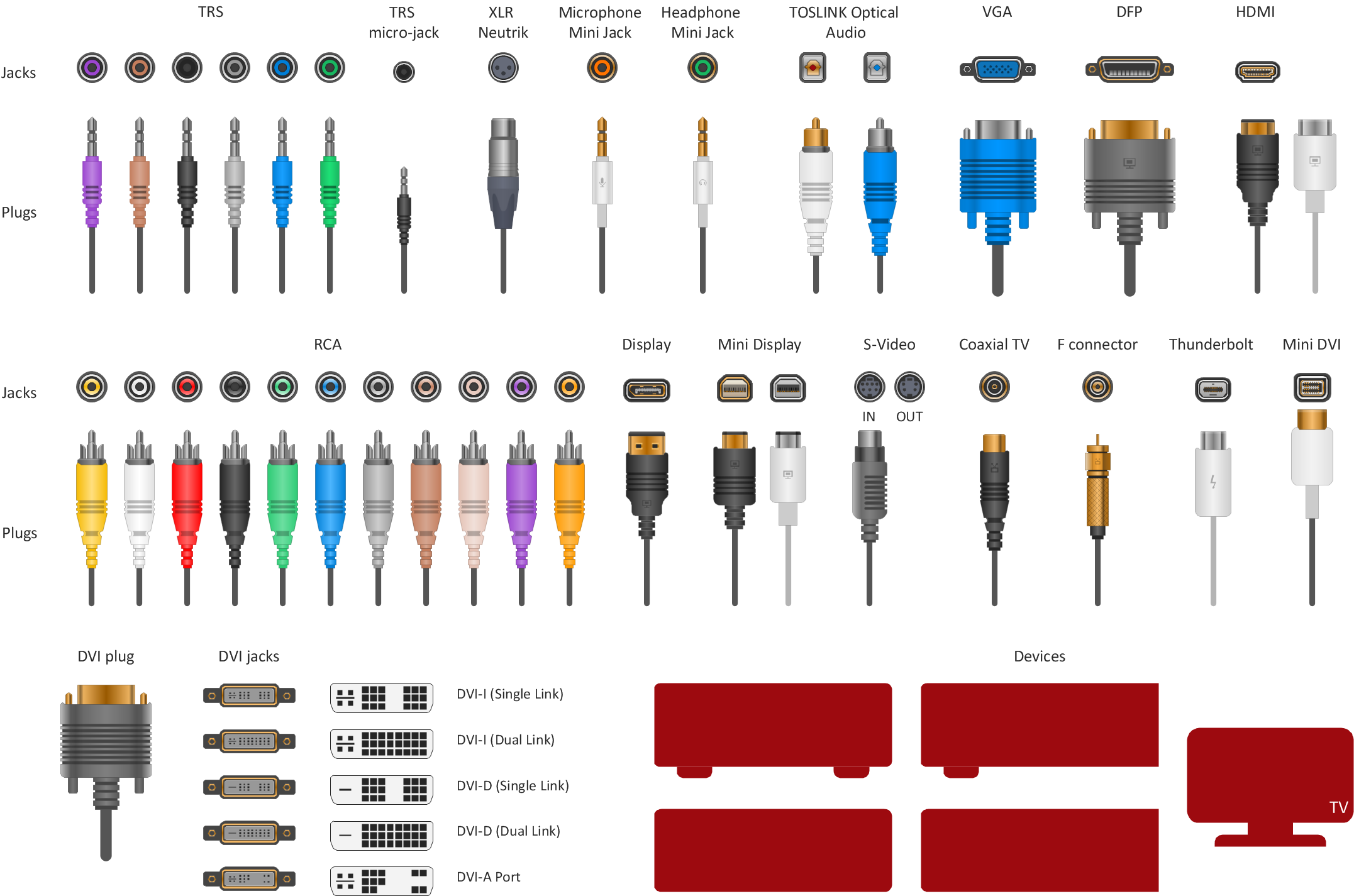
Sample 1. Vector stencils - Audio video connectors.
The Audio and Video Connectors solution from ConceptDraw Solution Park contains a library with vector stencils of jacks, plugs and silhouettes of audio and video devices for drawing the hook up diagrams using ConceptDraw DIAGRAM diagramming software.
TEN RELATED HOW TO's:
What do you know about restaurants? To have a better understanding, use restaurant floor plans software, and enjoy the result. Registration is going to take just a few minutes, and you will be able to start your experience from tons of examples and free templates.
This restaurant floor plan was created with the help of he ConceptDraw Cafe and Restaurant Plans solution. The main feature of this restaurant is small kitchen. Perhaps that is why the designer of this establishment, has paid great attention to interior diversity. The facilities of ConceptDraw DIAGRAM allow him to make this easily. Here are represented tables for two, for three or four visitors. A visitor can choose any of the bright multi-colored chairs and tables. The two tables at the right upper corner attract one's attention. They are strictly decorated and located near the second door. Probably they are for security service of the restaurant, which monitors to ensure that visitors do not run away without paying.
Picture: Restaurant Floor Plans Software
Related Solution:
Any factory needs a clear scheme of all the equipment used in the manufacture processes. So, if you want to place all your machines and equipment on one diagram, you need a good diagramming tool for that. For instance, you can find all the design elements you might need, such as lathes, milling machines or saws on ConceptDraw DIAGRAM Solution Park in Plant Layout Plans solution in appropriate libraries.
This drawing represents the Machines and Equipment library delivered by ConceptDraw Plant Layout Plans solution. This vector library is supplied along with other libraries related to industrial architecture planning and interior design.
Just planning the proper facilities in a proper right place, allows to manufacture a product in the most effective and economic way. Objects containing in these libraries will be helpful for architects and engineers dealing with industrial buildings design. They are intended to use for designing layouts of plants, warehouses, manufacturing workshop etc.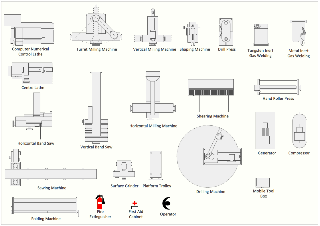
Picture: Interior Design. Machines and Equipment — Design Elements
Related Solution:
ConceptDraw Arrows10 Technology - This is more than enough versatility to draw any type of diagram with any degree of complexity.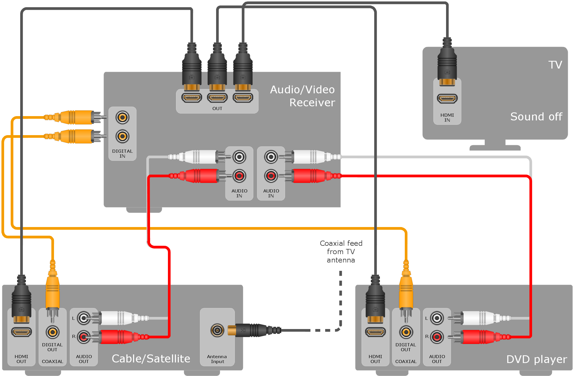
Picture: ConceptDraw Arrows10 Technology
This sample illustrates the Floor Plan of mini hotel representing the arrangement of hotel rooms, dining hall, and other premises all of them furnished. This is necessary for construction a hotel and is helpful for booking rooms for accommodation.
This sample was created in ConceptDraw DIAGRAM diagramming and vector drawing software using the Floor Plans Solution from the Building Plans area of ConceptDraw Solution Park.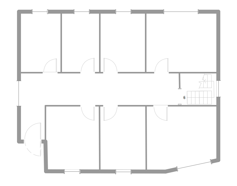
Picture: Hotel Floorplan
Related Solution:
Easy charting software comes with beautiful chart templates and examples. This makes it easy to create professional charts without prior experience.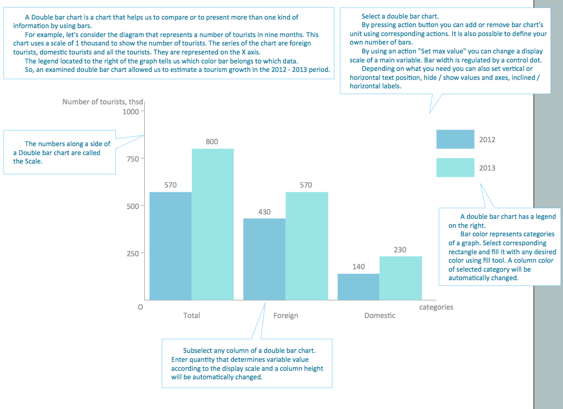
Picture: Chart Templates
This sample shows the Flowchart that displays the layout and work flow of the cloud marketing platform. This diagram has a style of the marketing brochure. This style displays the central product that is related to the other issues.
Using the ready-to-use predesigned objects, samples and templates from the Flowcharts Solution for ConceptDraw DIAGRAM you can create your own professional looking Flowchart Diagrams quick and easy.
Picture: Flowchart Marketing Process. Flowchart Examples
Related Solution:
ConceptDraw DIAGRAM is a powerful business and technical diagramming software tool that enables you to design professional-looking graphics, diagrams, flowcharts, floor plans and much more in just minutes. Maintain business processes performance with clear visual documentation. Effectively present and communicate information in a clear and concise manner with ConceptDraw DIAGRAM.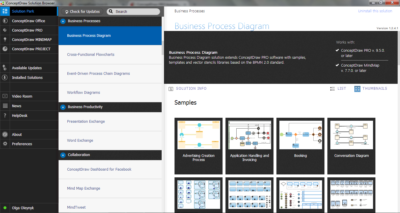
Picture: ConceptDraw DIAGRAM
The ConceptDraw DIAGRAM is a best Network Diagramming software.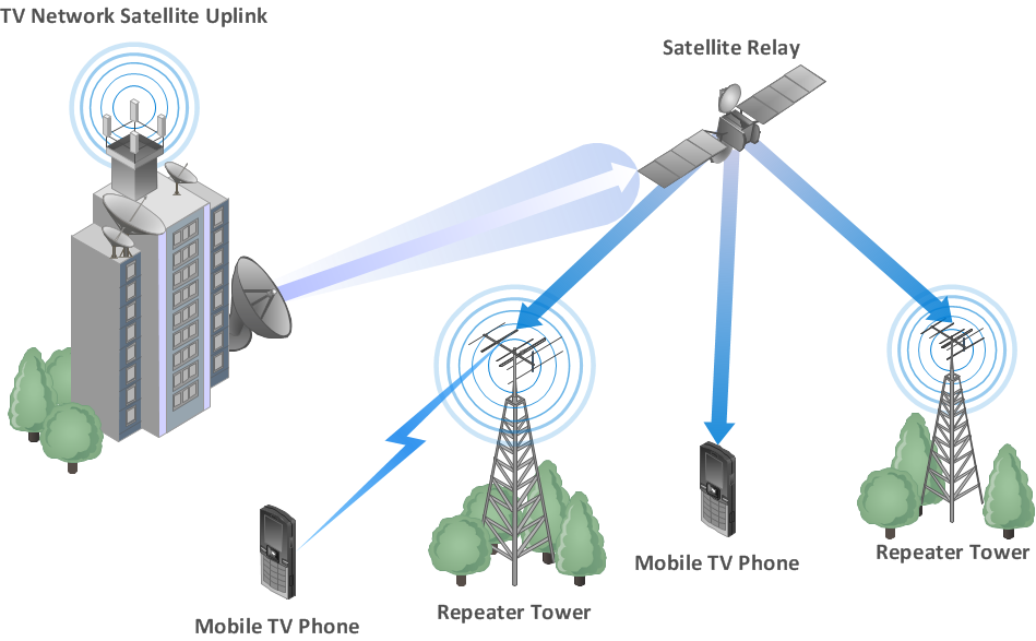
Picture: Building Networks
Related Solution:
The Audio & Video Connectors solution contains a set of pre-designed objects, libraries, templates, and samples; allowing quick and easy diagramming of various configurations of audio and video devices.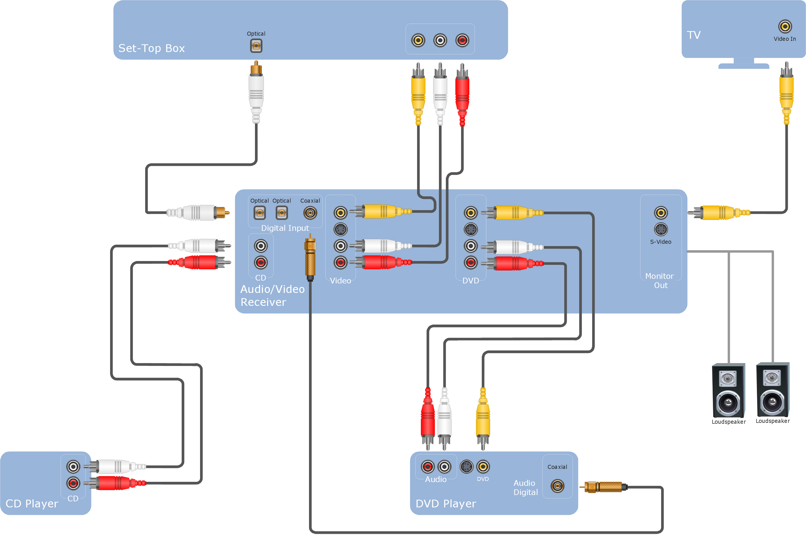
Picture: Audio Visual Cables and Connectors
Related Solution:
A Telecommunications network is a network of nodes, links, trunks and telephone switches that are connected, operated by telephone companies and realize telephone, audio, visual and data communications among the users. The telecommunications network can also include Internet, microwave, wireless equipment.
This example was created in ConceptDraw DIAGRAM using the Computer and Networks Area of ConceptDraw Solution Park and shows the Telecommunications network.
Picture: Telecommunication networks. Computer and Network Examples
Related Solution:
ConceptDraw
DIAGRAM 18