Electrical Symbols — Electron Tubes
Invented in 1904 by John Ambrose Fleming, vacuum tubes were a basic component for electronics throughout the first half of the twentieth century, which saw the diffusion of radio, television, radar, sound reinforcement, sound recording and reproduction, large telephone networks, analog and digital computers, and industrial process control. From the mid-1950s solid-state devices such as transistors gradually replaced tubes. However, there are still a few applications for which tubes are preferred to semiconductors; for example, the magnetron used in microwave ovens, and certain high-frequency amplifiers.
Pic. 1. Electron Tubes Library
ConceptDraw DIAGRAM is a powerful software for creating professional looking electrical diagram quick and easy. For this purpose you can use the Electrical Engineering solution from the "Engineering" area of ConceptDraw Solution Park.
Electrical Engineering Solution for ConceptDraw DIAGRAM provides the stencils libraries of ready-to-use predesigned 926 vector symbols, templates and samples that make your electrical drawing quick, easy and effective.
26 libraries of the Electrical Engineering Solution of ConceptDraw DIAGRAM make your electrical diagramming simple, efficient, and effective. You can simply and quickly drop the ready-to-use objects from libraries into your document to create the electrical diagram.
Pic. 2. Electrical Engineering symbols
Electrical diagram software will assist you in drawing your electrical diagrams with minimal effort and makes it very easy for beginners. Electrical symbols and smart connectors help present your electrical drawings, electrical schematic, wiring diagrams and blue prints.

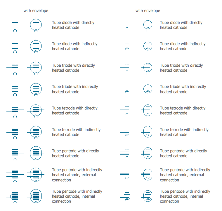
Pic. 3. Electrical Symbols — Electron Tubes
Most of the electrical symbols can be changed in their appearance, styles and colors according to users' requirements. Electrical symbols are used to represent various electrical and electronic devices in a schematic diagram of an electrical or electronic circuit.
The following table lists some electron tubes electrical symbols in our electrical diagram software.
Symbol | Meaning | |
Electrical Symbols — Electron Tubes | ||
![]() | Diode, directly heated | |
![]() | Diode, indirectly heated | |
![]() | Diode, envelope, direct. heated | |
![]() | Diode, envelope, indirect. heated | |
![]() | Triode, directly heated | |
![]() | Triode, indirectly heated | |
![]() | Triode, envelope, direct. heated | |
![]() | Triode, envelope, indirect. heated | |
![]() | Tetrode, directly heated | |
![]() | Tetrode, indirectly heated | |
![]() | Tetrode, envelope, direct. heated | |
![]() | Tetrode, envelope, indirect. heated | |
![]() | Pentode, directly heated | |
![]() | Pentode, indirectly heated, external connection | |
![]() | Pentode, indirectly heated, internal connection | |
![]() | Pentode, envelope, direct. heated | |
![]() | Pentode, envelope, indirect. heated, external connection | |
![]() | Pentode, envelope, indirect. heated, internal connection | |
![]() | Diode, directly heated 2 | |
![]() | Diode, indirectly heated 2 | |
![]() | Diode, envelope, direct. heated 2 | |
![]() | Diode, envelope, indirect. heated 2 | |
![]() | Triode, directly heated 2 | |
![]() | Triode, indirectly heated 2 | |
![]() | Triode, envelope, direct. heated 2 | |
![]() | Triode, envelope, indirect. heated 2 | |
![]() | Tetrode, directly heated 2 | |
![]() | Tetrode, indirectly heated 2 | |
![]() | Tetrode, envelope, direct. heated 2 | |
![]() | Tetrode, envelope, indirect. heated 2 | |
![]() | Pentode, directly heated 2 | |
![]() | Pentode, indirectly heated, external connection 2 | |
![]() | Pentode, indirectly heated, internal connection 2 | |
![]() | Pentode, envelope, direct. heated 2 | |
![]() | Pentode, envelope, indirect. heated, external connection 2 | |
![]() | Pentode, envelope, indirect. heated, internal connection 2 |
One classification of vacuum tubes is by the number of active electrodes, (neglecting the filament or heater). A device with two active elements is a diode, usually used for rectification. Devices with three elements are triodes used for amplification and switching. Additional electrodes create tetrodes, pentodes, and so forth, which have multiple additional functions made possible by the additional controllable electrodes.
How to Create an Electrical Diagram Using Electron Tubes Library
- Open ConceptDraw DIAGRAM new document page.
- Select libraries from Electrical Engineering section.
-
There are a few different ways to place an object into your drawing:
- Click on an object and then click on the document, at the place you want the object to be inserted.
- Perform a drag-and-drop from the library to your document.
- Double click on an object’s icon in the library to place an object in the center of your document.
- Select the Smart Connector tool
. To connect elements using this tool, drag the connector from one connect dot to another.You can use Layers to place connections on different layers.
- Result: Electrical Diagram.
TEN RELATED HOW TO's:
Electrical Symbols — Transformers and Windings →
A transformer is an electrical device that transfers electrical energy between two or more circuits through electromagnetic induction. Electromagnetic induction produces an electromotive force within a conductor which is exposed to time varying magnetic fields. Transformers are used to increase or decrease the alternating voltages in electric power applications. 26 libraries of the Electrical Engineering Solution of ConceptDraw DIAGRAM make your electrical diagramming simple, efficient, and effective. You can simply and quickly drop the ready-to-use objects from libraries into your document to create the electrical diagram.
Electrical Symbols — Semiconductor →
Semiconductors are crystalline or amorphous solids with distinct electrical characteristics. They are of high resistance — higher than typical resistance materials, but still of much lower resistance than insulators. Their resistance decreases as their temperature increases, which is behavior opposite to that of a metal. Finally, their conducting properties may be altered in useful ways by the deliberate, controlled introduction of impurities into the crystal structure, which lowers its resistance but also permits the creation of semiconductor junctions between differently-doped regions of the extrinsic semiconductor crystal. The behavior of charge carriers which include electrons, ions and electron holes at these junctions is the basis of diodes, transistors and all modern electronics. 26 libraries of the Electrical Engineering Solution of ConceptDraw DIAGRAM make your electrical diagramming simple, efficient, and effective. You can simply and quickly drop the ready-to-use objects from libraries into your document to create the electrical diagram.
Electrical and Telecom Plan Software →
While studying, many of the students encounter the necessity of remaking class projects, over and over. To facilitate this process you can use special electrical and telecom plan software, which helps altering projects in several clicks. Using templates will fasten your work, and you will have more free time. This sample represents an electrical and telecommunication floor plan. Electrical and telecom floor plans contain a floor plan , on which imposed the layout of electrical, and telecommunications equipment. They shows electrical and telecom details regarding the current floor of a building: lightening, fixtures, wires, outlets, circuit panels, etc. Using of standart notation of electrical and telecommunication symbols makes the plan understandable for engineers, architects, constructors, specialist in electricity and telecommunications.
Healthy Food Ideas →
Representation of healthy food ideas and designing illustrations for healthy food recipes, decoration healthy diet plan and drawing healthy foods images has never been easier than now thanks to the ConceptDraw DIAGRAM diagramming and vector drawing software enhanced with Health Food solution from the Food and Beverage area of ConceptDraw Solution Park.
Electrical Symbols — VHF UHF SHF →
Ultra high frequency (UHF) is the ITU designation for radio frequencies in the range between 300 MHz and 3 GHz, also known as the decimetre band as the wavelengths range from one meter to one decimetre. Radio waves with frequencies above the UHF band fall into the SHF (super-high frequency) or microwave frequency range. Lower frequency signals fall into the VHF (very high frequency) or lower bands. UHF radio waves propagate mainly by line of sight; they are blocked by hills and large buildings although the transmission through building walls is strong enough for indoor reception. They are used for television broadcasting, cell phones, satellite communication including GPS, personal radio services including Wi-Fi and Bluetooth, walkie-talkies, cordless phones, and numerous other applications. 26 libraries of the Electrical Engineering Solution of ConceptDraw DIAGRAM make your electrical diagramming simple, efficient, and effective. You can simply and quickly drop the ready-to-use objects from libraries into your document to create the electrical diagram.
Business Processes description with ConceptDraw DIAGRAM →
Business Processes description with ConceptDraw. Business-processes it allows to describe functional blocks, for example production and marketing. ConceptDraw lets creation of business processes description using IDEF0 and IDEF2 methods.
Flow chart Example. Warehouse Flowchart →
If you want to find a way to understand complex things in minutes, you should try to visualize data. One of the most useful tool for this is creating a flowchart, which is a diagram representing stages of some process in sequential order. There are so many possible uses of flowcharts and you can find tons of flow charts examples and predesigned templates on the Internet. Warehouse flowchart is often used for describing workflow and business process mapping. Using your imagination, you can simplify your job or daily routine with flowcharts. Warehouse flowcharts are used to document product and information flow between sources of supply and consumers. The flowchart provides the staged guidance on how to manage each aspect of warehousing and describes such aspects as receiving of supplies; control of quality; shipment and storage and corresponding document flow. Warehouse flowchart, being actual is a good source of information. It indicates the stepwise way to complete the warehouse and inventory management process flow. Also it can be very useful for an inventory and audit procedures.
Electrical Symbols — Switches and Relays →
In electrical engineering, a switch is an electrical component that can break an electrical circuit, interrupting the current or diverting it from one conductor to another. The mechanism of a switch may be operated directly by a human operator to control a circuit (for example, a light switch or a keyboard button), may be operated by a moving object such as a door-operated switch, or may be operated by some sensing element for pressure, temperature or flow. A relay is a switch that is operated by electricity. Switches are made to handle a wide range of voltages and currents; very large switches may be used to isolate high-voltage circuits in electrical substations. 26 libraries of the Electrical Engineering Solution of ConceptDraw DIAGRAM make your electrical diagramming simple, efficient, and effective. You can simply and quickly drop the ready-to-use objects from libraries into your document to create the electrical diagram.
Electrical Symbols — Stations →
A power station is an industrial facility for the generation of electric power. Most power stations contain one or more generators, a rotating machine that converts mechanical power into electrical power. The relative motion between a magnetic field and a conductor creates an electrical current. The energy source harnessed to turn the generator varies widely. Most power stations in the world burn fossil fuels such as coal, oil, and natural gas to generate electricity. Others use nuclear power, but there is an increasing use of cleaner renewable sources such as solar, wind, wave and hydroelectric. 26 libraries of the Electrical Engineering Solution of ConceptDraw DIAGRAM make your electrical diagramming simple, efficient, and effective. You can simply and quickly drop the ready-to-use objects from libraries into your document to create the electrical diagram.
Electrical Symbols — Qualifying →
A qualifying symbol is graphics or text added to the basic outline of a device’s logic symbol to describe the physical or logical characteristics of the device. 26 libraries of the Electrical Engineering Solution of ConceptDraw DIAGRAM make your electrical diagramming simple, efficient, and effective. You can simply and quickly drop the ready-to-use objects from libraries into your document to create the electrical diagram.