Electrical Symbols — Transformers and Windings
A transformer is an electrical device that transfers electrical energy between two or more circuits through electromagnetic induction, which produces an electromotive force within a conductor exposed to time-varying magnetic fields.
Since the invention of the first constant potential transformer in 1885, transformers have become essential for the transmission, distribution, and utilization of alternating current electrical energy. Many transformer designs are encountered in electronic and electric power applications. Transformers range in size, from RF transformers that are less than a cubic centimeter in volume to units interconnecting the power grid that weigh hundreds of tons.
Transformers are used to increase or decrease the alternating voltages in electric power applications and play a crucial role in the transmission and distribution of electrical power. The key components of a transformer are the core and the windings. The core is a static device that transmits power through electromagnetic induction, provides a path for the magnetic flux, and helps to reduce energy losses due to eddy currents.
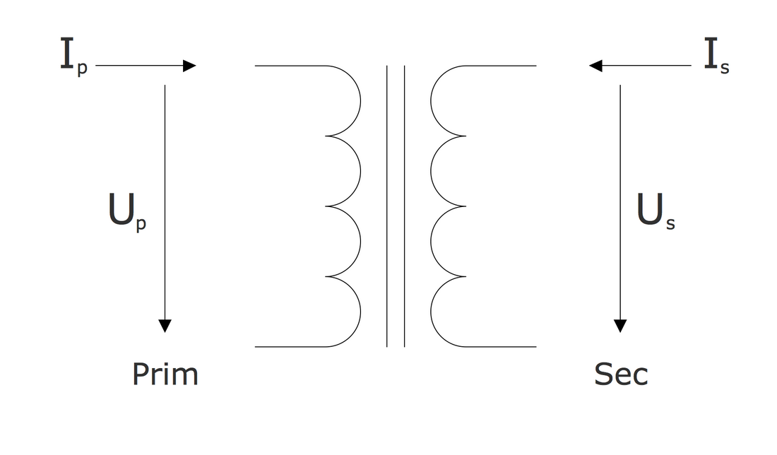
Two windings (primary and secondary) are coils of wire, typically made of copper or aluminum providing high conductivity and durability, wrapped around the core. The primary winding is connected to the input voltage source, it draws power and delivers the energy at the changed voltage to the load. The secondary winding is connected to the output circuit. The windings are typically insulated to ensure efficient operation and prevent electrical short circuits.
There are two winding configurations: step-up transformer, which number of turns in the secondary winding is greater than in its primary winding, and step-down transformer, which has vice versa fewer turns in the secondary winding than in the primary one. The transformers of these configurations increase or decrease the voltage correspondingly.
Efficiency affected by core material, winding resistance, and construction technique, is a key characteristic of transformers. Regular maintenance and testing of transformers is a necessity. It enhances efficiency and reliable performance and reduces energy losses that occur as a result of resistance of the windings, eddy current, or hysteresis. Increased voltage stress as a result of winding insulation failures decreases the transformer's life. Thorough testing of turns ratio and insulation resistance helps to detect deficiencies and eliminate them.
The Role of Windings in Transformer Functionality
Windings play an important role in transformers' functionality. They consist of coils of conductive wire wrapped around a magnetic core and enable the transferring of electrical energy between circuits through electromagnetic induction. The number of turns in the transformer's primary and secondary windings determines whether the transformer steps up (increases) or steps down (decreases) the voltage. Moreover, winding design and correct material selection are crucial for efficient operation and help to minimize energy losses.
The transformer's principle of work is based on Faraday's law of electromagnetic induction and mutual induction. In an ideal transformer, the same magnetic flux passes through both the primary and secondary windings, and a voltage in each of them is induced proportional to its number of turns. The magnitude of the voltage is affected by the direction of current flow in two windings or transformer polarity. The use of two coils in transformers helps to ensure efficient transmission over extended distances, safety, and mitigation of voltage spikes.
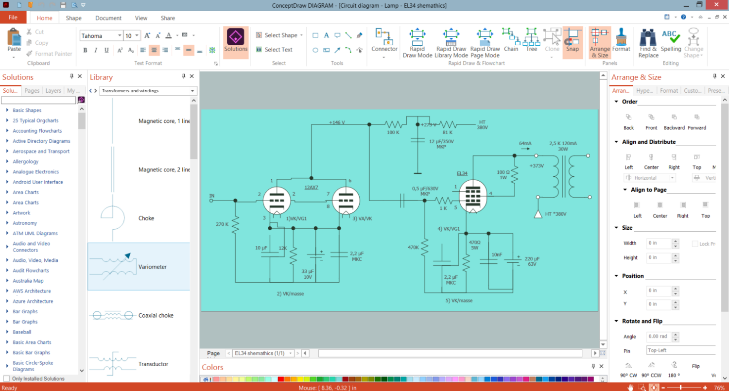
Example 1. Electrical Diagram Design in ConceptDraw DIAGRAM Software
Types of Transformers
Transformers are classified based on their construction, number and configurations of windings, functions, purpose, usage and application, core design, voltage conversion, number of phases, connections between windings, insulation, etc. These characteristics play a critical role in the operation and efficiency of transformers and help to meet certain needs. Each configuration provides defined advantages and has a specific application. Different types of transformer winding structures have been developed over the years. Nowadays they are utilized in a wide range of industries and understanding this classification and unique features is essential for choosing a suitable transformer correctly.
One differs:
single-phase and three-phase transformers;
step-up and step-down transformers;
single-winding and two-winding transformers;
autotransformers and isolation transformers;
power, distribution, and isolation transformers;
core-type, shell-type, and berry-type transformers;
current and potential transformers;
dry-type and oil-immersed transformers;
air-core, iron-core, ferrite-core, and toroidal-core transformers;
medium voltage control transformers, industrial control transformers;
general purpose and military transformers;
instrument transformers;
grounding or earthing transformers, etc.
Transformer Windings
Windings are a crucial component of transformers and play a significant role in their performance, efficiency, and reliability affected by used materials and design. High-conductivity materials, effective cooling techniques, and optimized winding configurations help to enhance performance and minimize losses. Transformer windings differ in their relative position, the direction and method of winding, the number of turns, and other characteristics. Precise and tight winding is also incredibly important, it allows reducing gaps and irregularities in order to enhance magnetic coupling and reduce losses.
There are two types of transformer windings:
- primary winding — gets electrical energy from the source;
- secondary winding — transmits electrical energy to the load.
Windings Materials, Design, and Efficiency
Transformer windings provide high efficiency, enhance performance and lifespan, and help to minimize losses due to the used materials and design. Common materials for transformer windings are aluminum and copper. Copper provides high electrical conductivity and thermal conductivity, mechanical strength, durability, and low resistance, which decreases energy losses. Aluminium is cheaper and more light equivalent with lower electrical conductivity and good corrosion resistance.
The windings are insulated with materials that provide high dielectric strength and thermal stability to prevent electrical short circuits and ensure safety and reliability, such as synthetic polymers, enamel, varnish, and others. The correct ratio of turns between primary and secondary windings helps to realize voltage transformation with minimal losses. The use of laminated core materials and optimal winding arrangements helps to reduce eddy current losses and improve efficiency.
Transformer windings are available in different types:
| Types of transformer windings | Description |
|---|---|
| Multi-layer | Windings are layered one on another providing a compact design |
| Helical windings or spiral | Coils are wound in a helical way |
| Disc | Include several discs of windings placed in series or parallel, providing good insulation and cooling and suitable for high-voltage applications |
| Foil | Windings made from a thin metallic sheet with an insulating coating, wound spirallyn |
| Cylindrical | Windings with low voltage, use up to 6.6 kV for kVA up to 600-750 |
| Cross-over | Windings are separated into several coils, this helps to decrease the voltage among contiguous layers in coils divided axially with a 0.5-1 mm distance |
Windings Configurations
There are different types of winding configurations:
| Types of winding configurations | Description |
|---|---|
| Separate | Used in standard step-up and step-down transformers, primary and secondary windings of which are electrically isolated from each other providing safety and voltage transformation |
| Tapped | Have multiple connection points called taps along their length and are used in autotransformers and voltage regulators for voltage adjustment and regulation |
| Sandwich or interleaved | include layered or interleaved windings to reduce leakage inductance and improve coupling in high-frequency and pulse transformers |
| Concentric | windings are wound concentrically around the core, providing reduced inductance and enhanced magnetic coupling |
Four basic winding configurations are used in three-phase power transformers:
- delta (Δ) configuration — windings are connected in a triangular loop providing balanced loads and reduced harmonics;
- wye (Y) or star connection — windings are connected to one end forming a neutral point and ensuring balanced power distribution;
- zigzag or interconnected start winding — three single-phase transformers connected in a zig-zag configuration to handle unbalanced loads, reduce harmonic distortion, ensure a neutral connection and ground fault protection;
- autotransformer winding — a single winding acts both as primary and secondary, with a common section, helping to regulate voltage.
Innovations in Transformer Winding Technologies
Nowadays, transformer winding technologies are improved in order to meet the growing demands of modern electrical systems. The improvements help to boost efficiency, performance, durability, and reliability through thermal management and eliminating energy losses, more compact designs, and use of innovations in materials, design, and manufacturing processes.
Among the last innovations are:
innovative winding configurations like interleaved windings, disc windings, and helical windings;
advanced insulation materials like synthetic polymer Nomex, thermally upgraded paper, and epoxy resins;
high-temperature superconducting (HTS) windings;
nano-coated wires;
amorphous metal cores helping to minimize core losses and enhance overall transformer efficiency;
self-healing materials that can repair minor damages automatically;
laser welding techniques improving the mechanical and electrical integrity of windings and reducing manufacturing defects;
3D printing and additive manufacturing;
computational design tools that increase precision in design and performance, optimize winding designs and reduce prototyping costs.
Comprehensive Guide: Transformer Winding Diagrams and Symbols
Transformer winding diagrams and transformer connection diagrams are an essential tool for engineers, technicians, and electricians to design, document, install, and maintain transformer systems. They give a comprehensive view of the transformers from different angles, visually represent components and connections in transformers, and their use in different electrical systems helping to provide accurate wiring and operation of the components, safety compliance, and reduce the risk of electrical failures.
The primary and secondary windings of a transformer can be connected in different configurations. Transformer winding diagrams and electrical diagrams with transformers use standardized electrical diagram symbols to ensure a visual and comprehensive representation of an electrical system, the transformer’s functionality, and the transmission of electric power according to relevant standards and regulations. Often these diagrams include also technical information, such as voltage, dimensions, and other details.
Transformer winding diagrams are helpful in understanding the complexities of transformer systems, setting up transformers, and troubleshooting. Plan and design transformer setups creating detailed diagrams, ensure all connections and configurations are correct. All changes to electrical diagrams should be also carefully considered before being implemented to avoid safety risks.
Electrical Symbols for Transformers and Windings
The standardized symbols for transformers, windings, inductors, coils, regulators, cores, and other electrical components and connections are used in electrical schematics and diagrams. There are many different standard transformer configurations and each of them has its own schematic symbol. Transformer symbol in electrical drawing, in particular three phase transformer symbol and other types of transformers and windings are generally excepted, as well as other electrical symbols.
The use of standardized transformers winding symbols is crucial for creating accurate and understandable electrical diagrams and in particular, transformer winding diagrams. These symbols facilitate documentation of transformer systems, troubleshooting, maintenance, and communication of engineers, electricians, and technicians.
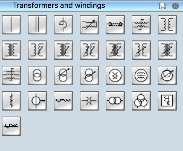
Example 2. Transformers and Windings Library
ConceptDraw DIAGRAM Electrical Design Software
ConceptDraw DIAGRAM is a powerful software for creating professional-looking electrical diagrams quickly and easily. For this purpose, you can use the Electrical Engineering solution from the Engineering area of ConceptDraw Solution Park.
Electrical Engineering solution for ConceptDraw DIAGRAM provides the stencils libraries of ready-to-use predesigned 926 vector electrical schematic symbols and wiring symbols, templates, and samples. 26 libraries of the Electrical Engineering solution of ConceptDraw DIAGRAM software make your electrical diagramming quick, simple, and efficient. You can easily drop the ready-to-use objects from libraries into your document to create the electrical diagram or electrical wiring diagram.
Example 3. Electrical Engineering symbols
Electrical diagram software will assist you in drawing your electrical diagrams with minimal effort and makes it very easy for beginners. Electrical symbols and smart connectors help to present your electrical drawing, electrical schematic, wiring diagrams, and blueprints.
Most of the electrical plan symbols can be changed in their appearance, styles, and colors according to users' requirements. Electrical symbols are used to represent various electrical and electronic devices in a schematic diagram of an electrical or electronic circuit.

Example 4. Electrical Symbols — Transformers and Windings Library
Transformers and Windings library included in the Electrical Engineering solution for ConceptDraw Solution Park provides all variety of transformers and windings symbols. Use them to create transformer winding designs and electrical diagrams with transformers efficiently.
The following table lists some transformers and windings electrical symbols in our electrical diagram software.
| Symbol | Meaning | |
| Electrical Symbols — Transformers and Windings | ||
 | Magnetic core, 1 line | |
 | Magnetic core, 2 lines | |
 | Choke | |
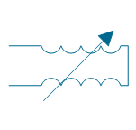 | Variometer | |
 | Coaxial choke | |
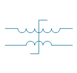 | Transductor | |
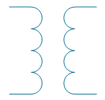 | Air-core transformer | |
 | Magnetic-core transformer | |
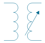 | Air-core transformer, 1 winding adjustable | |
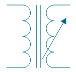 | Magnetic-core transformer, 1 winding adjustable | |
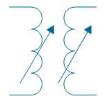 | Air-core transformer, 2 windings adjustable | |
 | Magnetic-core transformer, 2 windings adjustable | |
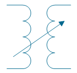 | Air-core transformer, mutual inductor | |
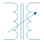 | Magnetic-core transformer, mutual inductor | |
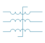 | Saturating transformer | |
 | Transformer 2 | |
 | Adjustable transformer, 1 winding | |
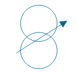 | Adjustable transformer, mutual inductor | |
 | 1-phase induction voltage regulator | |
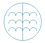 | Triplex induction voltage regulator | |
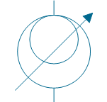 | Induction voltage regulator | |
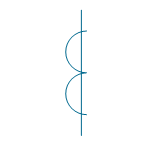 | Current transformer 1 | |
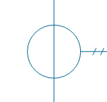 | Current transformer 2 | |
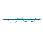 | Current transformer 3 | |
 | Potential transformer | |
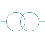 | Potential transformer 2 | |
 | Potential transformer with 3 windings | |
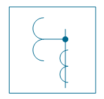 | Outdoor metering device | |
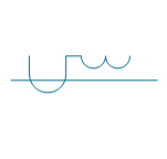 | Linear coupler | |
How to Create an Electrical Diagram Using Transformers and Windings Library
Follow the simple steps to create an electrical transformers diagram or an electrical diagram using transformers:
- Open ConceptDraw DIAGRAM new document page.
- Select libraries from the Electrical Engineering section.
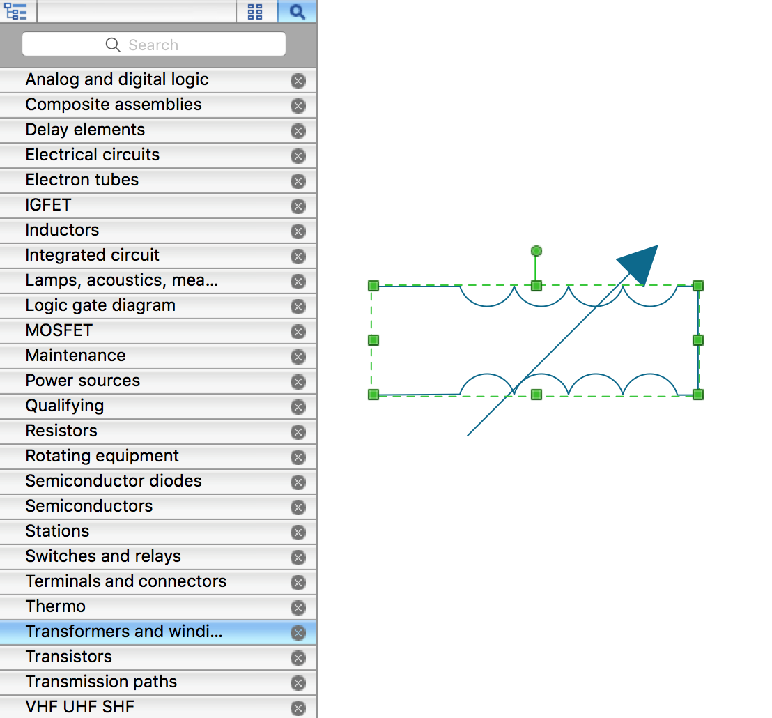
There are a few different ways to place an object into your drawing:
- Click on an object and then click on the document, at the place you want the object to be inserted.
- Perform a drag-and-drop from the library to your document.
- Double-click on an object’s icon in the library to place an object in the center of your document.
- Select the Smart Connector tool
 . To connect elements using this tool, drag the connector from one connect dot to another.You can use Layers to place connections on different layers.
 - Result: Electrical Diagram.
Conclusion
Transformers have a wide application in different areas from small electronic devices and electrical equipment to large power generation, transmission, and distribution networks. They are essential devices in electrical engineering for voltage regulation, charging current and the impedance of a circuit, managing, and distributing electrical power, and isolation in electrical and electronic circuits.
ConceptDraw DIAGRAM software is a great assistant in designing different kinds of electrical diagrams including the transformer diagrams and schematics with transformers in their composition, simple transformer diagram or complex electrical designs. These diagrams help in the precise design of both simple and complex winding geometries, choosing the type of transformer correctly to fully correspond to your current requirements, and help in the precise manufacturing of both heavy industrial machinery and small sensitive electronic equipment.
The development and using innovations help to create more efficient and reliable electrical systems and manufacture modern and more compact transformers. The transformer wiring diagrams help to control quality and manufacturing precision and implement strict testing to ensure that the windings meet design specifications and performance standards.


