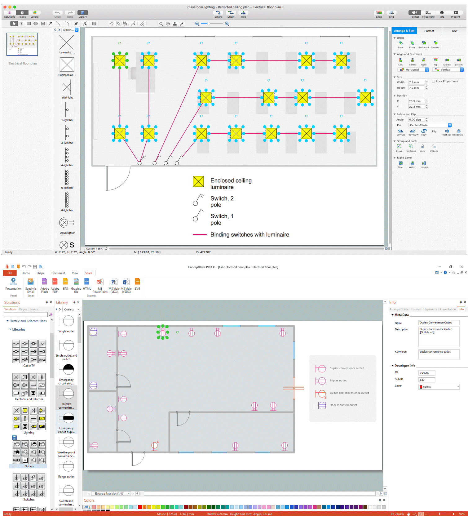
Pic. 1. Electrical and Telecom Plan Software
ConceptDraw DIAGRAM powerful diagramming and vector drawing software provides Electric and Telecom Plans solution that allows draw Electrical and Telecom Plans quick, easy and effective.
Electrical and Telecom Symbols

Pic. 2. Electrical and Telecom Symbols
Electrical and Telecom library of Electric and Telecom Plans solution contains a large number of predesigned vector symbols of electrical and telecommunication equipment. You can simply drop them into your document to design professional looking Electrical and Telecom Plans.
Electrical and Telecom Design House Plan Example
Electric and Telecom Plans solution also includes collection of examples and templates that you can use and change for your needs.

Pic. 3. Electrical and Telecom Design House Plan Example
This example was created in ConceptDraw DIAGRAM using the Electric and Telecom Plans solution from the Building Plans area of ConceptDraw Solution Park. It shows the Electrical and Telecom Design Plan of the house.
The Electrical and Telecom Plans produced with ConceptDraw DIAGRAM are vector graphic documents and are available for reviewing, modifying, converting to a variety of formats (image, HTML, PDF file, MS PowerPoint Presentation, Adobe Flash or MS Visio), printing and send via e-mail in one moment.
NINE RELATED HOW TO's:
Computer networks nowadays are spread all across the world. The large number of parameters, such as geographic scale or communication protocols, can divide networks. One of the most common types of networks is called local area network (LAN). It convenient to represent network examples by means of diagrams.
This local area network (LAN) diagram provides an easy way to see the way the devices in a local network are interacted. The diagram uses a library containing specific symbols to represent network equipment , media and the end-user devices such as computers (PC, mac, laptop) , network printer, hubs, server and finally a modem. There are two types of network topologies: physical and logical. The current diagram represents precisely a physical type of LAN topology because it refers to the physical layout of a local network equipment.
Picture:
What is a Local Area Network?
Examples of LAN Diagrams
Related Solution:
Have you ever created the fire plans on the base of Fire Evacuation Plan Template? It's incredibly convenient and time-saving way. Let's try to make sure this with Fire and Emergency Plans solution for ConceptDraw DIAGRAM software.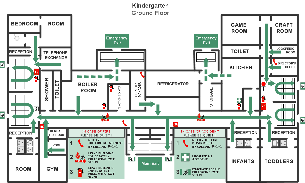
Picture: Fire Evacuation Plan Template
Related Solution:
Now it’s easy to share your visual documents with other people in a form most convenient for them.
ConceptDraw DIAGRAM can save your drawings and diagrams in a number of highly useful formats, including graphic files. You can save your drawing as a.PNG,.JPG, or other graphic format file.
Picture: Export from ConceptDraw DIAGRAM Document to a Graphic File
How to create a Residential Electric Plan quick and easy? The simplest way is to use the tools of ConceptDraw DIAGRAM software extended with Electric and Telecom Plans Solution.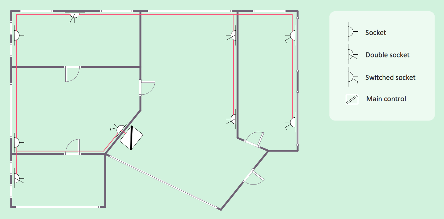
Picture: Residential Electric Plan
Related Solution:
A block diagram is a diagram of a system in which the principal parts or functions are represented by blocks connected by lines that show the relationships of the blocks. ConceptDraw DIAGRAM diagramming and vector drawing software extended with Block Diagrams Solution from the Diagrams Area is a powerful Block Diagram Creator.
Picture: Block Diagram Creator
Related Solution:
Planning a water supply system is one of the stages of developing a building drawing. Although materials are constantly improved, design elements for plumbing haven't changed sufficiently for decades. This is due to necessity of maintaining very old systems.
The plan and schematic drawing of plumbing equipment, water pipe junctions and, kitchen facilities a is a rather significant element of a building plan. The suite of 4 vector libraries supplied with ConceptDraw solution for Plumbing and Piping Planning includes near 130 vector images of pipes, boilers, water pipe junctions, tanks and other plumbing devices, helpful when creating plumbing and piping plans, and blueprints of sewerage or water supply systems.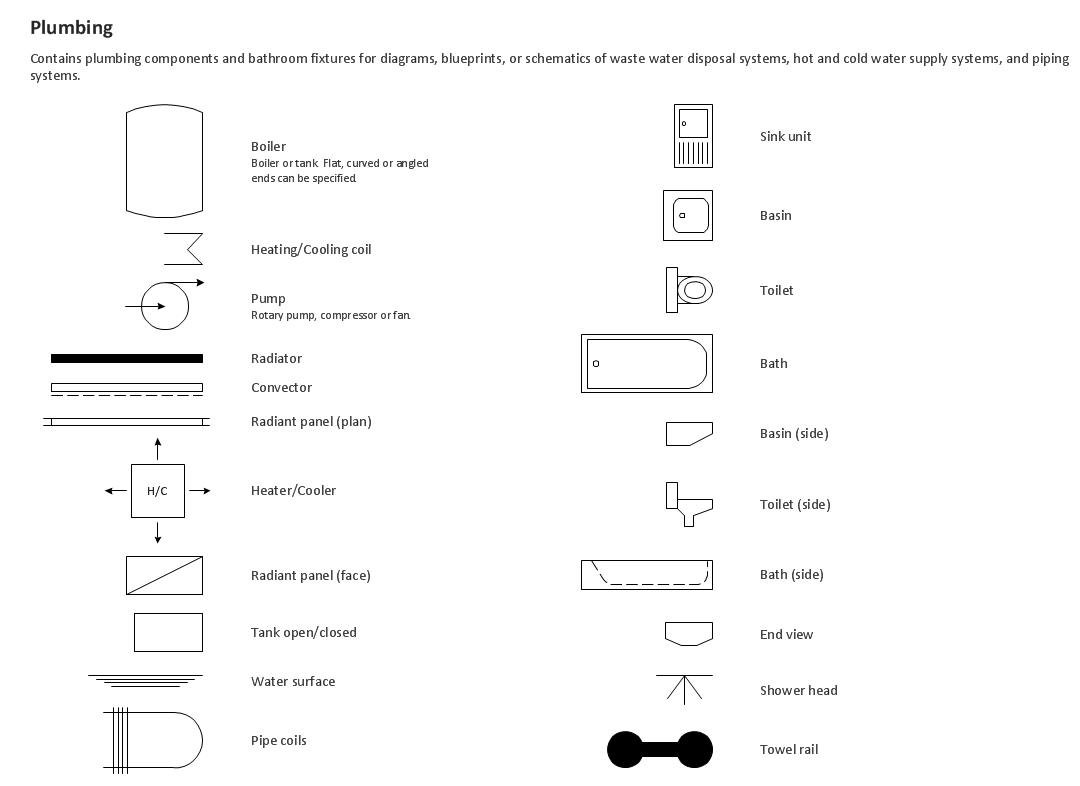
Picture: Building Drawing. Design Element — Plumbing
Related Solution:
Using ConceptDraw you will be able to create bubble diagrams from the ready ConceptDraw library objects or make your own objects. The created diagram can be saved and edited, objects can be moved and links between them will be automatically repainted after object moving because of using the ConceptDraw connectors.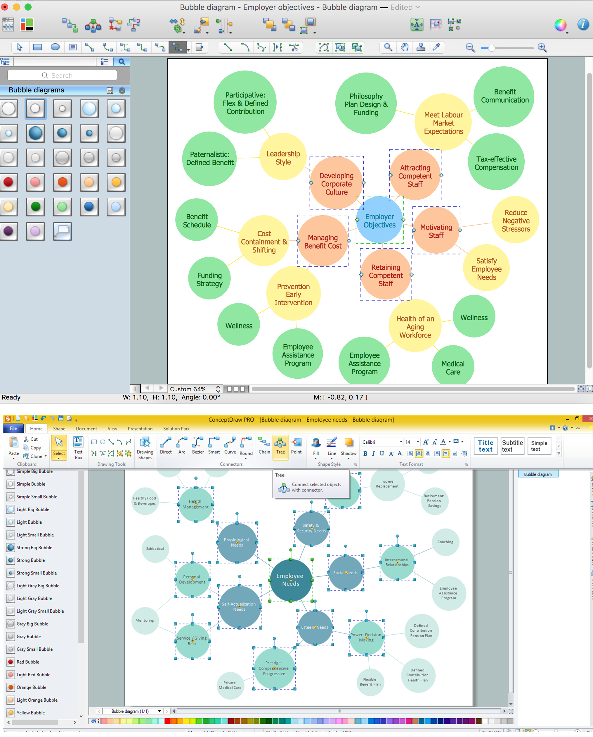
Picture: Bubble diagrams with ConceptDraw DIAGRAM
Related Solution:
This sample shows diagram of the electrical wiring of the apartment. You can see the arrangement of the sockets and the main control on this diagram. The electrical diagram is the important part of the architectural project.
Using the predesigned objects, templates and samples of the Electrical Engineering solution for ConceptDraw DIAGRAM you can create your own professional electrical diagrams, wiring diagrams quick and easy.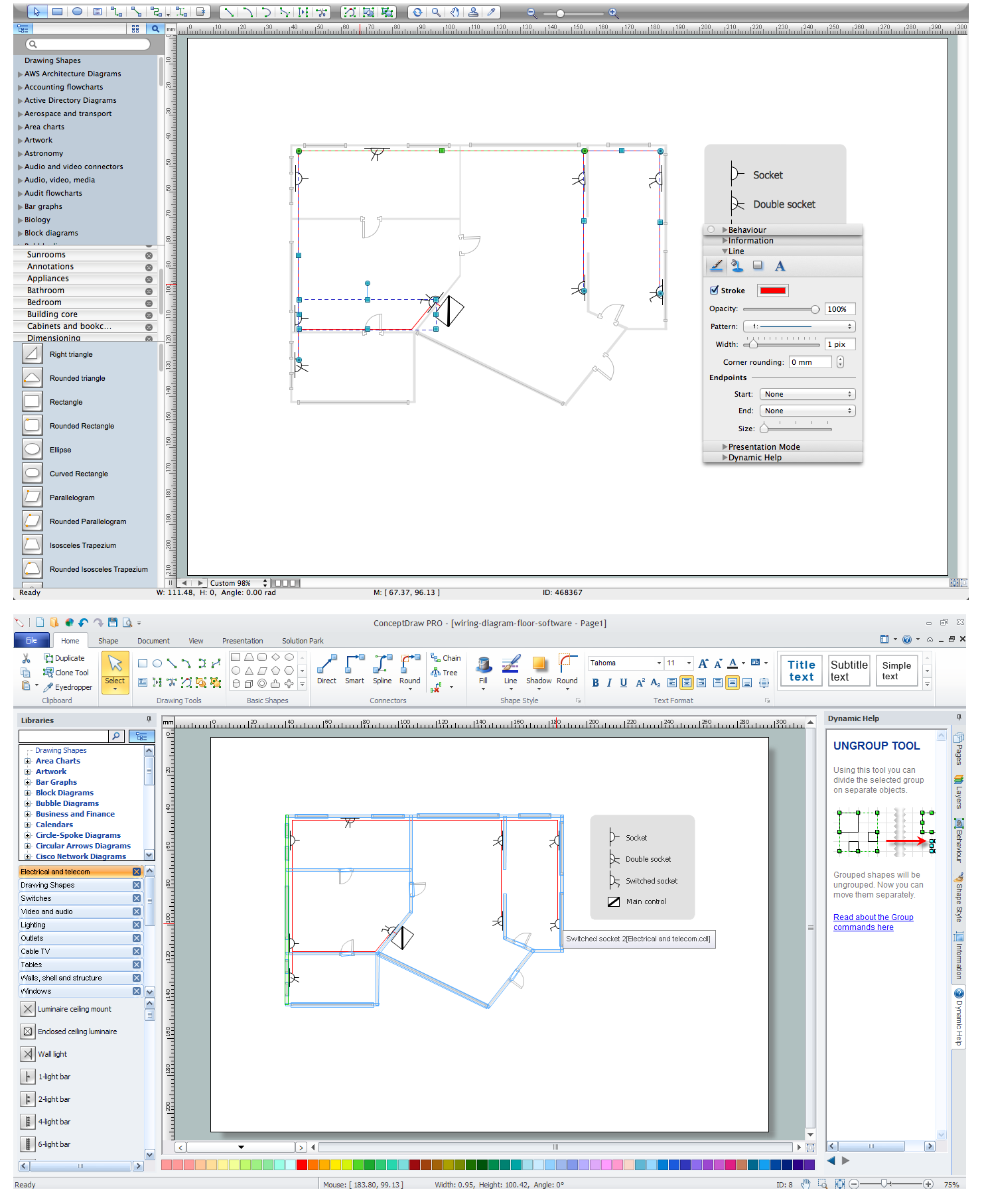
Picture: Wiring Diagram Floor Software
Related Solution:
Design of any premises includes many stages and variety of plans. Ceiling plans are also included in this number. Reflected Ceiling Plans Solution from the Building Plans Area for ConceptDraw DIAGRAM software will help you represent and realize any of your ceiling ideas for living room.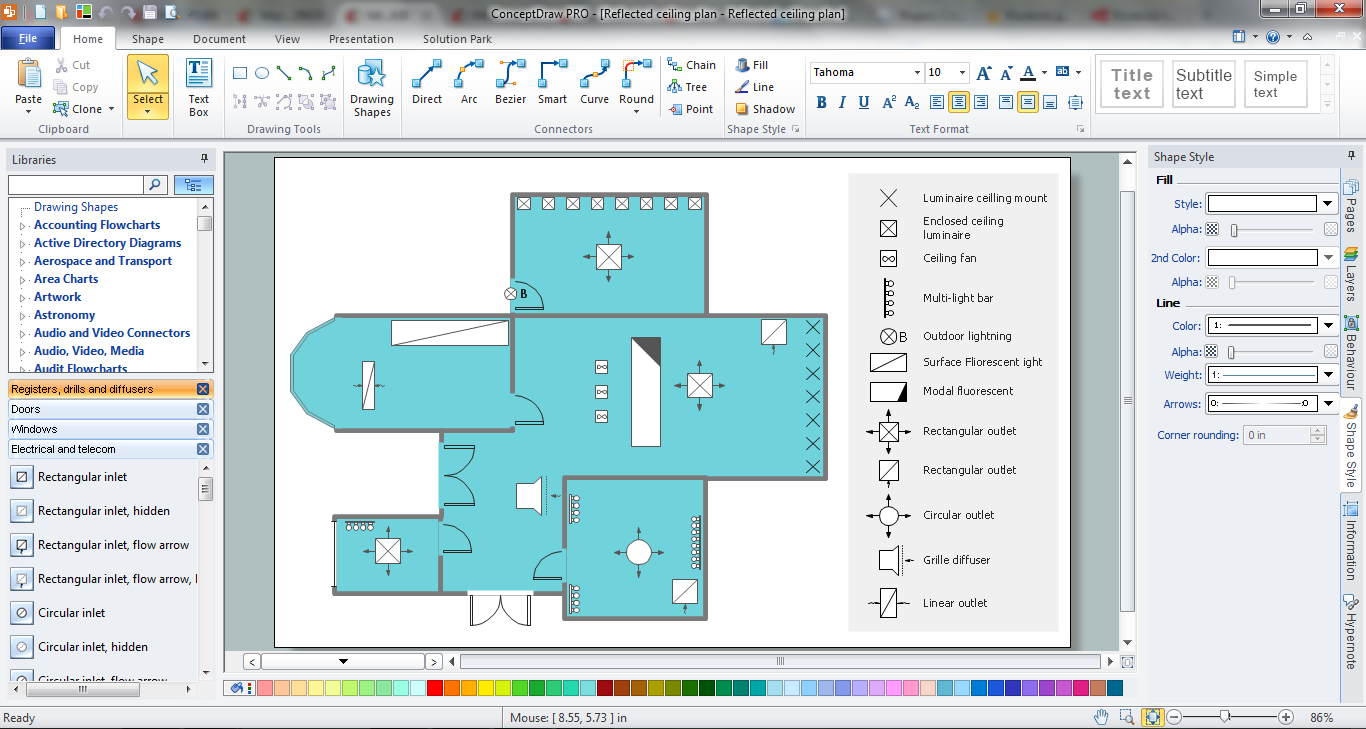
Picture: Ceiling Ideas For Living Room
Related Solution:

