How To use Electrical and Telecom Plan Software
Electrical and Telecom Plan Software
When drawing Electrical and telecom plan, you need to display electrical circuit, schematics, electrical wiring, digital circuits and house electrical plans, etc. It shows the electrical devices location and the scheme of electric and telecom wiring clearly and concisely enough.
For easy start, use Electric and Telecom plan solution templates and samples which will be opened right with standard electrical symbols and icons library. Or create your own electrical and telecom diagrams. Try now to make sure how easy and neat drawing electrical and telecom plan could be with ConceptDraw DIAGRAM
Just drag and drop electrical and telecom symbols (such as wall light and down lighter, light bar, circuit breaker, switch, etc.) to your drawing, join, combine, group, align and distribute elements the way you need.
ConceptDraw DIAGRAM helps you to create eye-catchy professional-looking diagrams in minutes and extends your work with various export methods.
Use Electrical and Telecom Plan Software is a fast way to draw:
- home electrical plan,
- residential electric plan,
- telecom wireless plan,
- electrical circuit diagrams,
- telecom plans
and other electric visual and telecommunication floor plans for design and construction, including outlets, switches, and fixtures.
You can use many of built-in templates and examples of our House Electrical Plan Software. Start with the exact template you need then customize it to fit your needs with more than 1000 telecom and electrical symbols used in electrical and telecom plans, switch, light bar, circuit breaker, wall light, down lighter, outdoor lighting, floor receptacle, modular fluorescent fitting, office lamp, etc. You will find expected result in minutes.

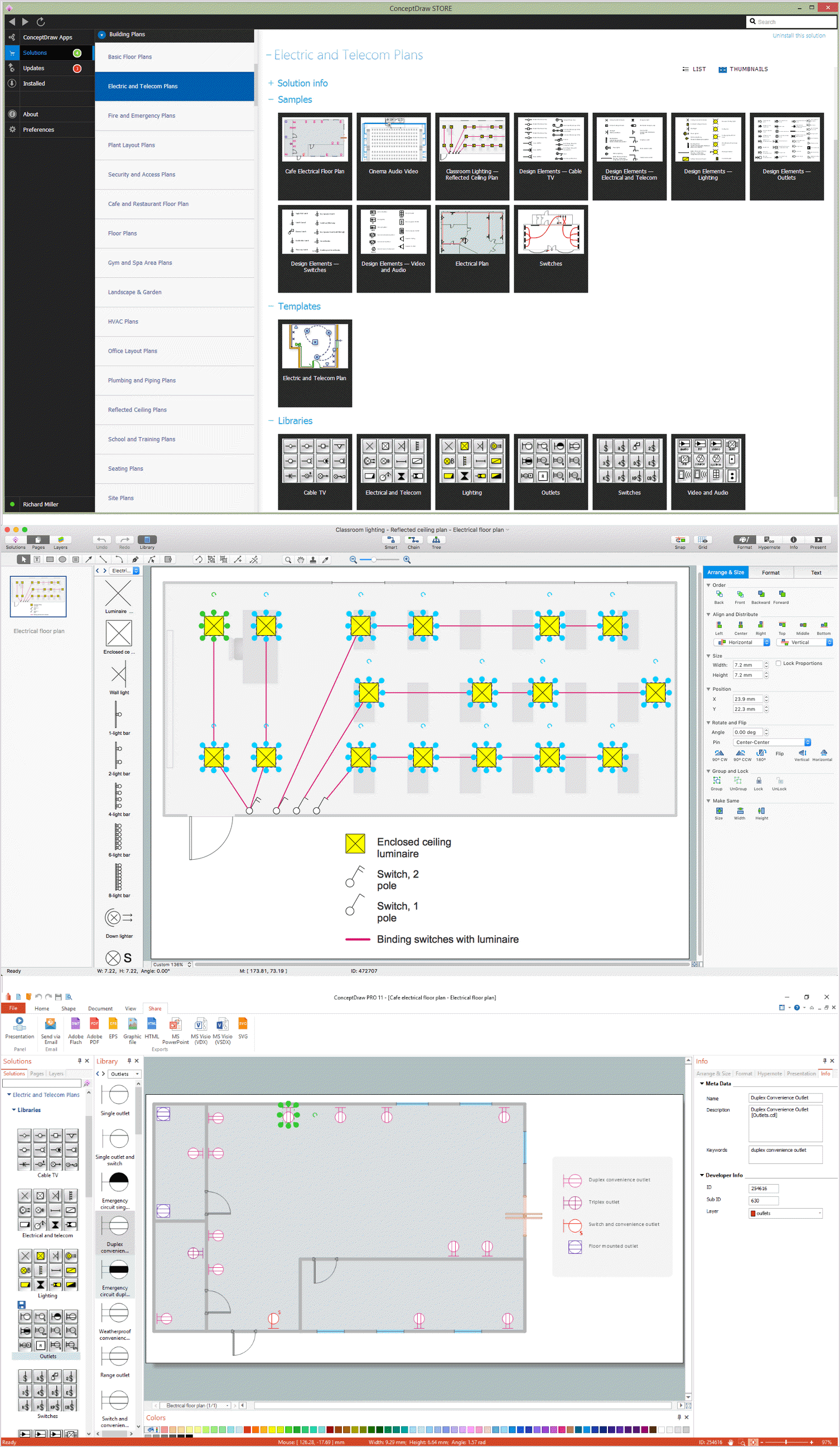
Example 1. Telecom Plan and Electrical Symbols
Look at this sample which illustrates the home electrical plan. You can see the visual detailed plan of the home and adjacent territory, location of numerous electrical devices in the building and the scheme of electric and telecom wiring.
Example 2. Electrical and Telecom Design Software
Design and manage household or business electrical systems using Electric and Telecom Plans solution.
TEN RELATED HOW TO's:
You need quickly design Gym Layout Plan? ConceptDraw DIAGRAM software supplied with Gym and Spa Area Plans solution from Building Plans area of ConceptDraw Solution Park will help you to handle this task.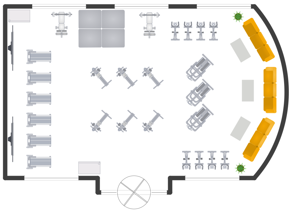
Picture: Gym Layout
Related Solution:
Plumbing systems are very important for any manufacture, and it's a good practice to have a clear scheme of that system. To create one, you should use a piping and instrumentation diagram software with a possibility to save files in vector format, so you can print them without quality loss. ConceptDraw DIAGRAM is a great tool for creating diagrams, and you don't need to be very experienced to use it efficiently.
This example of Piping and Instrumentation Diagram (P&ID) depicts a scheme that illustrates the physical sequence and functional communications of piping, instrumentation and plumbing equipment components of a typical food trailer.
Seeking to avoid health troubles in a mobile food service , the plumbing demands for food trailers must be considered accurately. This P&ID shows all of piping including a basic set of piping system components along with multiple sinks, extra water heaters and other elements to meet health guidelines.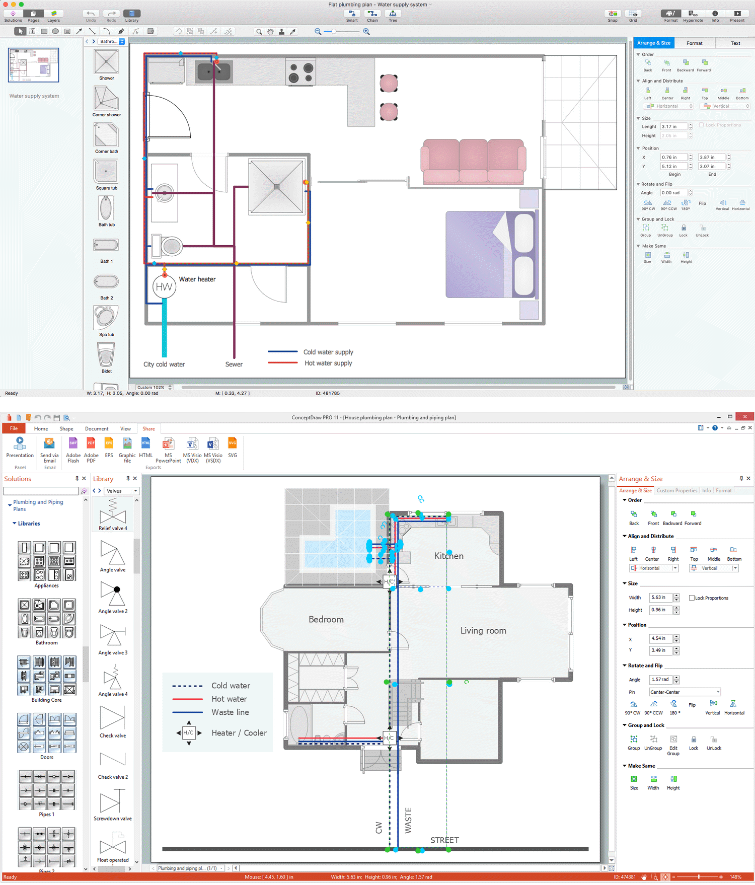
Picture: Piping and Instrumentation Diagram Software
Related Solution:
At the base of the identity of an organisational is its organizational culture.
Picture: Pyramid Diagram
Related Solutions:
The ConceptDraw Home Design Software extended with Floor Plans solution from the Building Plans area of ConceptDraw Solution Park offers the powerful tools which will help you in easy developing vivid and professional-looking: Building plans, Home plans, House designs, Floor plans, Home interior designs, Furniture and equipment layouts.
Picture: Home Design Software
Related Solution:
ConceptDraw DIAGRAM software extended with Electric and Telecom Plans Solution is the best software for drawing the Telecom Wireless Plan of any complexity.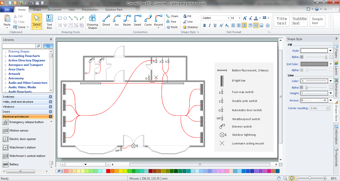
Picture: Telecom Wireless Plan
Related Solution:
ConceptDraw DIAGRAM diagramming and vector drawing software enhanced with Electrical Engineering Solution from the Industrial Engineering Area of ConceptDraw Solution Park offers you powerful tools and libraries with incredibly large quantity of predesigned electrical symbols as electrical schematic symbols for easy designing professional looking Electrical Schematics.
Picture: Electrical Symbols, Electrical Schematic Symbols
Related Solution:
Communication via Internet nowadays is almost irreplaceable part of lifestyle. It’s needless to say that providing that communication is not a piece of cake, and network diagram software is useful for representing all the interconnections between network devices. These diagrams are also helpful for educational purposes.
This drawing depicts the network topology of the sample web studio. This is a physical type of network diagram. It is depicting the network, end-user equipment and connections between them. The given network has combined the both star and mesh network topology features. This diagram is a tool of network administrator. it delivers the actual information on location of servers, hubs, switches, routers, and other telecommunication equipment. The collection of network related symbols provided with ConceptDraw Network Diagrams solution represents the entire network components. All Symbols are standard. Therefore, network specialists can effortlessly decrypt this diagram.
Picture: Network Diagram Software
Related Solution:
These libraries of vector objects depict the Site Accessories and Parking and Roads elements. They are needed to draw architectural and landscape plans that show the architectural elements around buildings: parking spaces, hiking and biking trails, drainage systems, lights, and vehicle access control elements. These libraries are included into ConcepDraw solution for Site Planning. Site Accessories and Parking, Roads libraries contain near 40 vector images that will help depict an a surrounding territory at building plans.
These libraries of vector objects depict the Site Accessories and Parking and Roads elements. They are needed to draw architectural and landscape plans that show the architectural elements around buildings: parking spaces, hiking and biking trails, drainage systems, lights, and vehicle access control elements. These libraries are included into ConcepDraw solution for Site Planning. Site Accessories and Parking, Roads libraries contain near 40 vector images that will help depict an a surrounding territory at building plans.
Picture: Building Drawing. Design Element Site Plan
Related Solution:
The Audio & Video Connectors solution contains a set of pre-designed objects, libraries, templates, and samples; allowing quick and easy diagramming of various configurations of audio and video devices.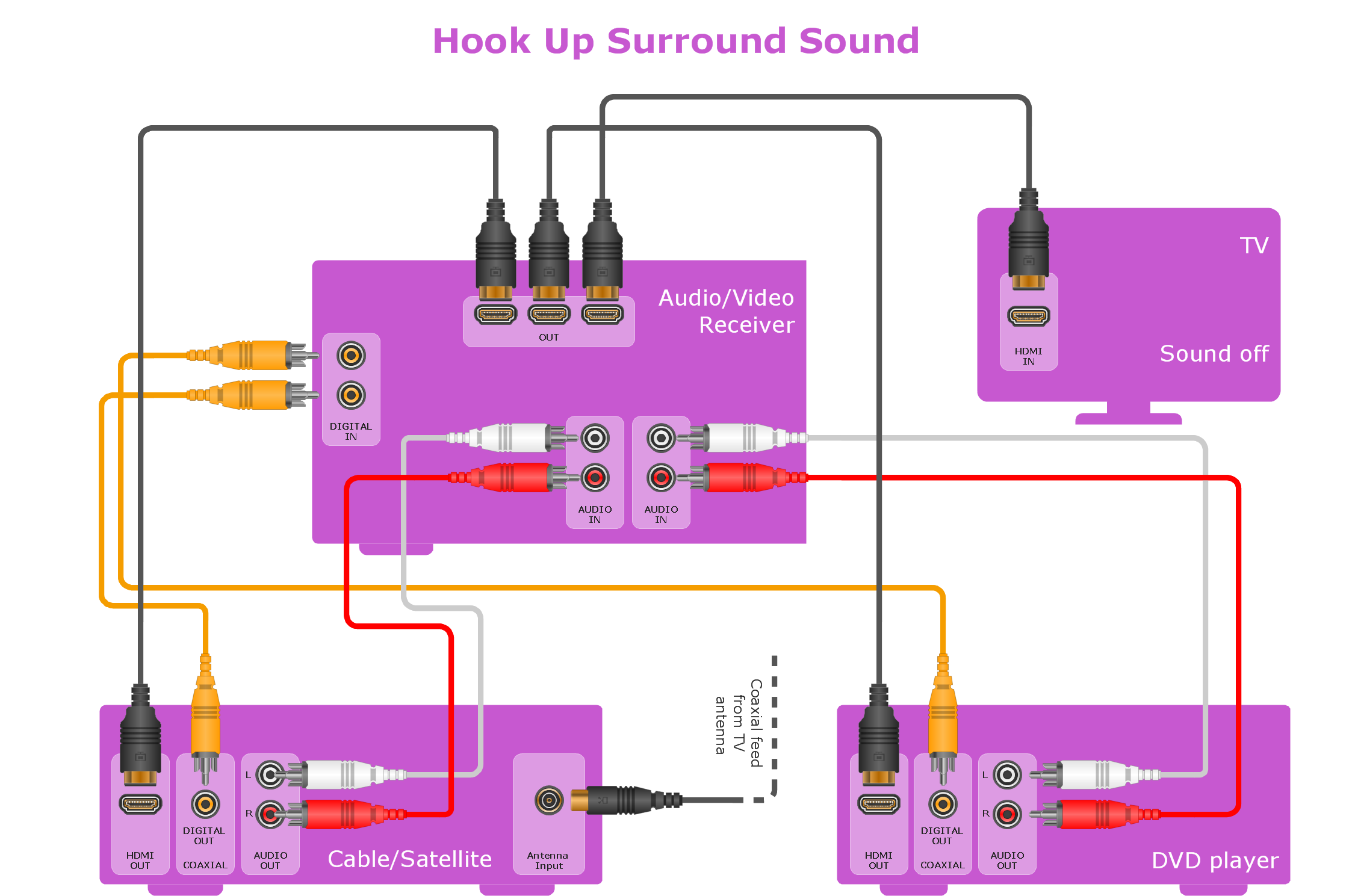
Picture: Making Your Audio and Video Connections
Related Solution:
ConceptDraw DIAGRAM is a Wireless Network Drawing Mac OS software.
Picture: Wireless Networking for Mac
Related Solution:
