Electrical Circuits — Electrical Symbols
An electrical circuit is a closed pathway or closed loop through which electrical energy transfers. It consists of a set of interconnected components that work together to provide a continuous and uninterrupted flow of electrons — electric current, which allows processing signals, power devices, and appliances, and performing computations. The electrical circuit components include resistors, inductors, capacitors, power sources, switches, control devices, protective devices, current dividers, and other components that are all connected by wires.
The electrical circuit is fraught with great danger, so protective components and measures are essential to ensure the safe functioning of electrical circuits. Grounding is the first measure that provides stability and safety to protect people from the dangerous effects of electric current and electric shock through reducing voltage and pathing it to return to the earth after achieving a reference point. Such danger as a short circuit occurs as a result of the interaction of two conductors with different potentials, which is not provided for by the design of the device and disrupts its normal operation and as a result, can cause damage or fire. Safety devices like fuses and breakers protect electrical circuits against overcurrent and short circuits by interrupting the electrical flow when necessary. Filters are used to increase the quality of signals by removing unwanted frequencies from a signal.
In a closed circuit, an electric current flows from the positive terminal of the power source to the negative one through the electrical circuit components. Ohm's Law is the main law applied to electrical circuits and helps to calculate voltage, current, and resistance because describes the linear relationship between the current and voltage in a section of the circuit. It states that electric current through a conductor between two points is directly proportional to the voltage across these points. At the same time, the load in a circuit refers to the components that consume electric power.
Basic Components of Electrical Circuits
Basic components of the electrical circuit include:
| Basic Components | Description |
|---|---|
| Resistors | Limit the amount of current flowing through a circuit in order to provide the correct voltage and current to the components and prevent their damage |
| Capacitors | Store and release electrical energy as needed helping to smooth out fluctuations in voltage, and are key components in filter circuits to remove unwanted noise from signals |
| Inductors | Store energy in a magnetic field, stabilize current and resist changes in it being used in transformers, power supplies, filters, etc |
| Batteries | Provide the necessary direct current voltage to power circuits |
| Switches | Control the flow of current in a circuit and are used to turn devices on and off |
| Transistors | Act as switches or amplifiers and provide control of the current flow in response to an input signal |
| Transformers | Change the voltage of electricity in the circuit, increase or decrease it |
| Relays | Provide control of the current flow by closing and opening the circuits electronically or electromechanically |
| Oscillators | convert DC signals to periodic AC signals, often a sine wave or square wave to be used as clock signals for digital circuits or audio applications |
| Current divider | Split the total current among parallel branches in proportion to their resistance |
| Connectors | Join different parts of a circuit to ensure a stable electrical connection |
These components are combined according to the desired purpose. Often the resistors, capacitors, and inductors are used together to build passive filters, through which only electronic signals of certain frequencies can pass. This ensures the modifying and transferring of signals that meet the requirements of the next stage of the circuit and as a result, the correct operation and accurate data transmission.
The combination of resistors and capacitors connected in series with a voltage source in RC circuits allows the capacitor to charge up to the voltage of the source but with a rate of charge limited by the resistor.
The combination of inductors and capacitors in LC circuits can create resonance when inductance and capacitance cancel out each other, i.e. the inductive and capacitive reactances are equal and opposite to each other. This has an application when tuning radios and signal processing. By combining resistors in series, a voltage divider can be created, allowing to distribute input voltage.

Example 1. Electrical Diagram — Simple Switched Supply
Types of Electrical Circuits
Electrical circuits can have different specific design considerations and operational requirements and are classified into several categories based on such criteria as signal type, used components, configuration, purpose, frequency range, power handling capacity, and others. Based on these criteria, they provide different characteristics and functionalities and have diverse applications.
First of all, one differs:
AC circuits — use alternating current that periodically changes its direction on the reverse one.
DC circuits — use direct current that flows only in one direction.
Based on the configuration, one differs (their combination is also possible):
Series circuits — the circuit components are connected in a line and form a single path for current flow.
Parallel circuits — the circuit components are connected across common points and current flows in multiple paths.
Based on purpose these are:
Power circuits — transmit and also distribute high currents and voltages.
Signal circuits — process and transmit low-power signals in communication and control systems.
Control circuits — control the operation of machines and equipment by using relays, timers, and switches.
Based on power handling capacity one differs:
Low-power circuits — are used for small currents and voltages like in portable electronics and sensors.
High-power circuits — operate large currents and voltages and are used in power supplies, electric motors, and industrial equipment.
Based on signal type one differs:
Analog circuits — use continuous signals varying in amplitude and frequency.
Digital circuits — use discrete signals representing binary states, these are 0 and 1.
Low-frequency circuits — operate at low frequencies up to a few kHz and are used in audio systems.
Radio-frequency circuits — operate at frequencies from kHz to GHz and are used in wireless communication and radar systems.
Based on the used components there are:
Passive circuits — contain passive components like resistors, inductors, capacitors.
Active circuits — include active components like transistors, operational amplifiers, integrated circuits.
Signal Processing in Electrical Circuits
Signal processing in electrical circuits is a critical aspect of modern electronics, which helps to develop efficient and high-performance electronic systems. It involves converting or transforming data, the analysis, interpretation, and other actions with electrical signals to extract information, optimize signals and improve their quality through detecting errors and correcting them, as well as ensure data integrity.
Using filters is a key signal-processing way. They help to remove noise and enhance desired signal features. In particular, adaptive filters allow the adjusting of filter parameters dynamically to optimize performance in changing conditions. The modulation techniques are efficient in communication systems, help to modify signal properties and provide reliable data transmission over various media. Digital signal processing provides converting analog signals into digital.
Understanding Electrical Power and Energy in Circuits
Understanding electrical power and energy in circuits is crucial for using energy efficiently as well as designing and operating electrical systems successfully. Also, correct evaluation of the energy efficiency helps to:
optimize the power consumption and energy usage;
ensure reliable operation of electronic components;
prevent overheating;
minimize disruptions (voltage spikes, sags, and harmonic distortions);
design energy-efficient systems that help reduce operational costs and environmental impact.
Analysis of load and thermal management also have great value and help to evaluate power, efficiency, and energy requirements.
Applications of Electrical Circuits in Everyday Life
Electrical circuits play a crucial role in countless aspects of everyday life. They enable various functionalities that we currently often take for granted, however we possess such treasure relatively recently. Electrical circuits provide:
lighting of different kinds;
powering of devices, household appliances, heating, ventilation, and air conditioning (HVAC) systems, and manufacturing machines;
communication and entertainment, computing systems and specific equipment such as telephone networks, mobile phones, the internet, audio systems, television sets, computers, laptops, medical equipment, security systems, and other devices;
transportation uses electrical circuits for ignition systems, lighting, electric propulsion, etc.
These applications highlight the pervasive influence of electrical circuits in enhancing convenience, efficiency, safety, and also quality of life across various domains.

Example 1. Electrical Circuit Diagram Design in ConceptDraw DIAGRAM
Electrical Circuit Diagrams
Electrical circuit diagrams or electrical circuit schematics are graphical representations of electrical circuits, which use standardized symbols and notation for electrical components and connections within a circuit. They provide a simplified overview of a circuit and focus on components and their connection in opposition to wiring diagrams, which show the physical layout of wires and components in a circuit.
Electrical circuit diagram and electrical circuit schematic are a standardized way to document electrical circuits on the stage of designing, installation, and maintenance of electrical circuits in electrical engineering and electronics. Their creation and use are prescribed by regulatory standards for designing diagrams of this type, power consumption and energy efficiency, safety and environment influence with a goal to ensure compliance with laws and reduce the carbon footprint of electrical devices.
Electrical circuit diagrams show a high-level overview of a system or circuit, its overall structure, functional blocks, and interconnections between subsystems. They are essential for communication between engineers and technicians, analyzing circuits' behavior, identifying faults, and troubleshooting. The correct evaluation of different characteristics helps to estimate energy consumption and choose the correct equipment according to energy requirements, ensure the appropriate battery capacity, modernize the system, integrate renewable energy sources, etc. Analyzing the power consumption of various components allows specialists to optimize the overall operation of a circuit or system.
Circuit Diagram Design in ConceptDraw DIAGRAM
A circuit diagram and electrical wiring diagram use symbols to represent parts of a circuit. Electrical and electronic circuits and different electronic diagrams can be complicated. However, making a drawing of the connections to all the component parts in the circuit's load makes it easier to understand how circuit components are connected.
ConceptDraw DIAGRAM is a powerful software for creating professional-looking electrical diagram quick and easy. For this purpose, you can use the Electrical Engineering solution from the "Engineering" area of ConceptDraw Solution Park.

Pic. 1. Electrical Circuits Library
Electrical Engineering Solution for ConceptDraw DIAGRAM electrical schematic diagram maker provides the stencils libraries of ready-to-use vector symbols, templates, and samples that make your electrical circuit drawing and wiring quick and easy.
26 libraries of the Electrical Engineering solution of ConceptDraw DIAGRAM software with 926 predesigned electrical diagram symbols make your electrical diagramming simple and efficient. You can simply and quickly drop the ready-to-use objects from libraries into your document to create your own electrical diagram.

Pic. 2. Electrical Engineering Symbols
Electrical diagram software will assist you in drawing electrical circuits and electrical diagrams with minimal effort and makes it very easy for beginners. All symbols of electric circuit and smart connectors help to present your electrical drawings, electrical schematic, wiring diagrams, and blueprints.

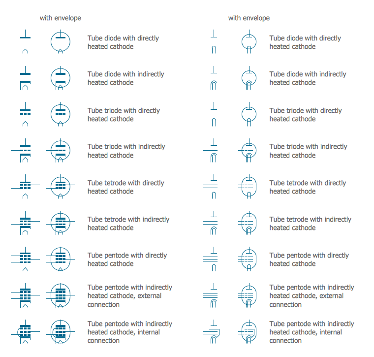
Pic. 3. Electrical Symbols — Electrical Circuits Library
Most of the electrical symbols can be changed in their appearance, styles, and colors according to users' requirements. Electrical symbols are used to represent various electrical and electronic devices in a schematic diagram of an electrical or electronic circuit.
The following table lists some electric circuit symbols in ConceptDraw DIAGRAM electrical diagram software.
| Symbol | Meaning | |
| Electrical Symbols — Electrical Circuits | ||
 | Ground | |
 | Equipotentiality | |
 | Chassis | |
 | Chassis 2 | |
 | Capacitor | |
 | Variable capacitor | |
 | Capacitor 2 | |
 | Variable capacitor 2 | |
 | Antenna | |
 | Antenna 2 | |
 | Circuit breaker | |
 | Fuse | |
 | Fuse 2 | |
 | Alarm fuse | |
 | Alarm fuse 2 | |
 | Circular generic component | |
 | Rectangular generic component | |
 | Transducer | |
 | Capacitive transducer | |
 | Non-capacitive transducer | |
 | Recording pickup head | |
 | Reproducing pickup head | |
 | Positive pulse | |
 | Negative pulse | |
 | Alternating pulse | |
 | Saw tooth | |
 | Positive step function | |
 | Negative step function | |
 | Explosive squib | |
 | Sensing link squib | |
 | Squib ignitor | |
 | Unspecified material | |
 | Solid material | |
 | Semiconducting material | |
 | Liquid | |
 | Insulating material | |
 | Gas | |
 | Electret | |
 | Surge protector | |
 | Multigap surge protector | |
 | Valve surge protector | |
 | Electrolytic surge protector | |
 | Carbon block surge protector | |
 | Protective gap surge protector | |
 | Sphere gap surge protector | |
 | Horn gap surge protector | |
 | Igniter plug | |
 | Circuit breaker | |
 | Junction | |
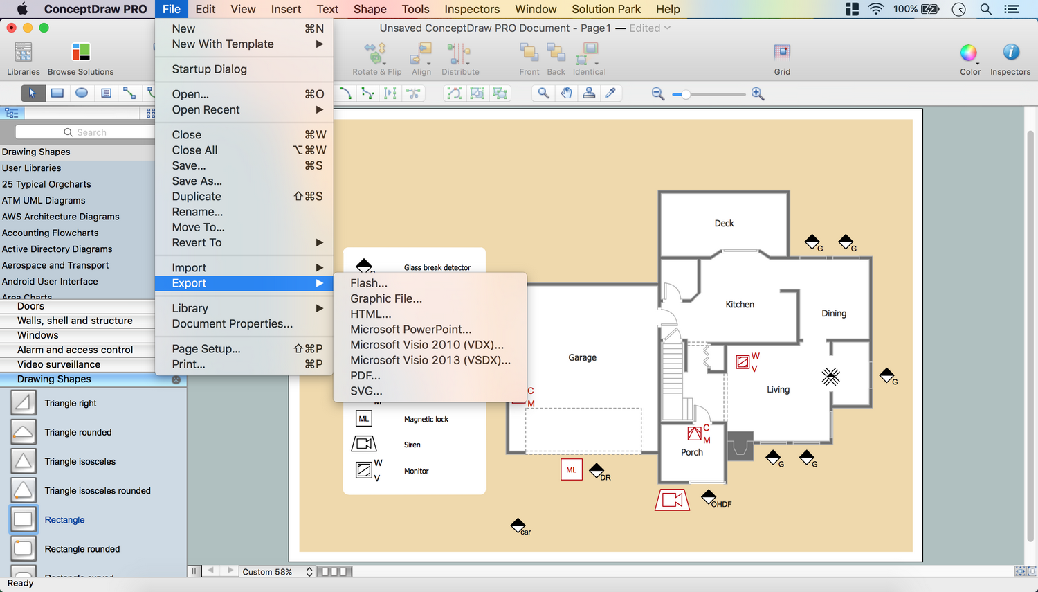
How to Create a Schematic of Circuit Using Electrical Circuits Library
To create an electrical diagram drawing, electrical schematic or circuit in ConceptDraw DIAGRAM software, follow the next steps:
- Open ConceptDraw DIAGRAM new document page.
- Select libraries from the Electrical Engineering section.

- Electrical circuits library contains objects, identified by a blue tile in the library pane. Such objects can be edited by using the Action button menu. To open the menu select an object and click the
 button in the upper right corner of the object.

- Select the Smart Connector tool
 . To connect elements using this tool, drag the connector from one connect dot to another. You can use Layers to place connections on different layers.


Benefits of ConceptDraw DIAGRAM electrical circuit design software
ConceptDraw DIAGRAM diagramming and vector drawing software enhanced with the Electrical Engineering solution is incredibly efficient to design diagrams representing all types of electrical circuits and plan wiring diagram. These include series and parallel circuits, power supply circuits, amplifier circuits, microcontroller circuits, and other types. The designed diagrams are able to expand the application of electronic devices across industries, suit to efficient development and implementation of electrical circuits, making research and implementing innovations, help to achieve energy efficiency, increase functionalities, and enhance performance of electrical devices and systems.