Pyramid Diagram
DIKW Pyramid
The so called “DIKW pyramid” is also known as the “DIKW hierarchy” as well as “wisdom hierarchy”, “knowledge hierarchy”, “information hierarchy” and the “data pyramid”. It refers to a class of models for representing the purported functional or/and structural relationships between information, data, wisdom and knowledge. Most of the versions of the “DIKW model” reference all mentioned 4 components and some of them include additional components. Apart from a pyramid and “hierarchy”, the “DIKW model” can also been characterized as a “chain”, as a continuum and as a “framework”. The presentation of the relationships among the previously mentioned “knowledge, information and data” in a hierarchical arrangement has been part of the language of information science for many years.
The “DIKW model” is often used in definitions of information, knowledge and data in such fields of business activity as the information systems, the information management as well as in the knowledge management and they can be created simply using ConceptDraw DIAGRAM software as well as the solutions from the ConceptDraw STORE, the application developed especially for ConceptDraw DIAGRAM users to make their process of drawing different diagrams, including the pyramid one, mentioned above, within a short period of time.
The information-data–knowledge components of “DIKW” can be referred to a class of at least five models, such as a “function data”, “information” and “knowledge”, being conceived of an “objective” or “subjective”, or both of them. Within the DIKW model, data is conceived of as signs or symbols, which all represent signals or stimuli. Sometimes, data is understood to be referred not only to the mentioned symbols, but also to signals referred to by the described symbols, known to be a “subjective data”. Data itself can be characterizes the “discrete and objective facts or observations, that are unprocessed and unorganized, and have no value or no meaning because of lack of interpretation and context. Thus, if these “facts” have a fundamental property, then they are true, having so called “objective” reality, and, vice versa, if it’s false, the it is known to be a “nonsensical” data within the “DIKW model”.
Data also was defined by the American information scientist Glynn Harmon as "one or more kinds of energy waves or particles selected by a conscious organism or intelligent agent”, on the basis of a pre-existing frame or inferential mechanism in the agent or organism. Another definition of data can be the following: “it is information, that becomes the meaning of the sensory stimuli. Thus, data are sense stimuli, as well as/or their meaning.
The so called “subjective data” is comparable to knowledge by acquaintance, confirming that it is based on the direct experience of “stimuli”. At the same time, the definition of data within “DIKW” is known to include the “Zins's subjective data” and it can have a meaning or it can have no meaning at all. Data is known to be consistently defined to include the "symbols", representing the “empirical stimuli” with help of them. In this sense, data are "recorded” symbols, which can be stored or captured, including numbers, text, images and diagrams, which are known to be the building blocks of communication.
Within the DIKW study, information meets the definition for knowledge in a way of describing things. Thus, descriptions contain information. Information can be always inferred from data in a way of answering the so called “interrogative” questions, such as "what", "who", "how many", "when" and "where". Answering the mentioned questions can lead to making the data useful and so it can be used for making decisions as well as actions. Taking into consideration the previous explanation, it’s fair to say that information can be defined as data, being endowed with both purpose and meaning.
DIKW model looks like a set of textbooks, with help of which it is simpler to describe any needed information in a way of an organized as well as structured data. Creating a DIKW Pyramid using ConceptDraw DIAGRAM software, can be a challenge, but you always have a choice of making DIKW Hierarchy, Knowledge Hierarchy, Wisdom Hierarchy, Information Hierarchy or Knowledge Pyramid, using the existing examples from the “Pyramid Diagrams solution”, which can be also found and downloaded from ConceptDraw STORE application, which was designed especially for the purpose of simplifying the ConceptDraw DIAGRAM users’ work with creating the diagrams, including the DIKW Pyramid.

Example 1. Pyramid Diagram Solution
Referring the mentioned DIKW Pyramid to a class of models, for a purpose of representing the purported functional as well as structural relationships between information, knowledge, wisdom and data, you can always rely upon ConceptDraw DIAGRAM as a great as well as very convenient tool for making your drawings within only a few hours or even a few minutes, depending on how good you know ConceptDraw DIAGRAM application so far. This DIKW pyramid diagram samples can be found and so downloaded both in the mentioned “Pyramid Diagrams solution” from ConceptDraw STORE application. Information is known to be conceived of as universal or subjective, or both, within the DIKW models.
Graphical representation of the DIKW diagram looks like a hierarchical model, similar looking to a pyramid, having data at its bottom as well as “wisdom”, but at its apex. Drawing the well-known Maslow’s “hierarchy of needs” with help of the mentioned ConceptDraw DIAGRAM software in a way of a pyramid, having each level of the hierarchy argued to be an essential precursor to the levels above, can be done only within a few minutes as all the needed tools for making such diagram will be provided to the ConceptDraw DIAGRAM users.
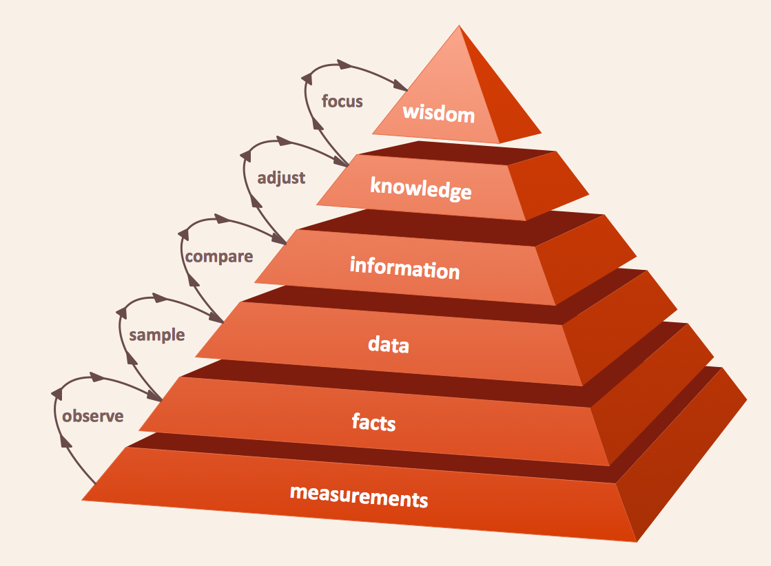
Example 2. Pyramid Diagram. DIKW hierarchy 3d pyramid
It’s commonly known that Maslow's hierarchy describes the relationships of priority, illustrating the lower levels being focused on first. But with DIKW, its model can describe the functional as well as the structural relationships, where the lower levels comprise the material of higher levels. It also can be represented as a two-dimensional chart as well as one or more flow diagrams, and all the mentioned drawings can be created within ConceptDraw DIAGRAM diagramming software.
See more Pyramid Diagram:
- Zooko Triangle Diagram
- Time, Quality, Money Triangle Diagram
- Project Triangle Diagram
- Purchase Funnel Diagram
- Project Triangle Chart
- Priority Pyramid Diagram
- Organization Triangle Diagram
- Knowledge Triangle Diagram
- Triangular Graphic
- Inverted Pyramid
- Fundraising Pyramid
- 3D Triangle Diagram
- DIKW Pyramid
- Five level pyramid model
- Four level pyramid model
- Three level pyramid model