Made with
ConceptDraw
DIAGRAM 18

Pyramid Diagram

Zooko Triangle Diagram

Zooko's triangle is known to be a trilemma which is a concept in international economics which states that it is impossible to have a fixed foreign exchange rate, a free capital movement and an independent monetary policy at the same time.

Due to the fact that it is a kind of three-properties trilemma, which are generally known to be considered as desirable for names of participants in a network protocol, Zooko’s triangle takes into consideration such three properties as human-meaningful one, security and decentralization.

Human-meaningful means that only meaningful as well as memorable and low-entropy names are being provided to the users. Secure because the amount of damage some malicious entity can inflict on the system should be the lower the better. Decentralized because all the names are correctly resolved to their respective entities without any use of a central service or authority.

The previously mentioned communication or network protocol is known to be a system of some particular rules that allow two or more than two entities of a communications system to transmit the information with the help of some kind of variation of a physical quantity. The protocol defines the synchronization and semantics of communication, the possible error recovery methods and the rules syntax. All protocols may be implemented by software, hardware, or a combination of both — hardware and software.

Lots of communicating systems use the well-defined formats to use for exchanging different messages. Each of such messages has an exact meaning that is intended to elicit a response from a range of possible responses pre-determined for some situation in particular. The particular behavior can be independent in terms of how it has to be introduced.

Communications protocols have to be previously agreed on by all the parties involved. In order to reach some agreement, a protocol may be developed into a technical standard. A programming language is known to be describing the same for computations, so there is a close analogy between programming languages and protocols as protocols are used for identifying what programming languages are to computations.

There are a few systems which are known to be exhibiting all three properties of Zooko's triangle that have now been created. A few platforms are known to be implementing the refutations of Zooko's conjecture. The examples may be Twister, Blockstack, Namecoin (as it has a separate blockchain) and Monero OpenAlias.

Pyramid Diagram *

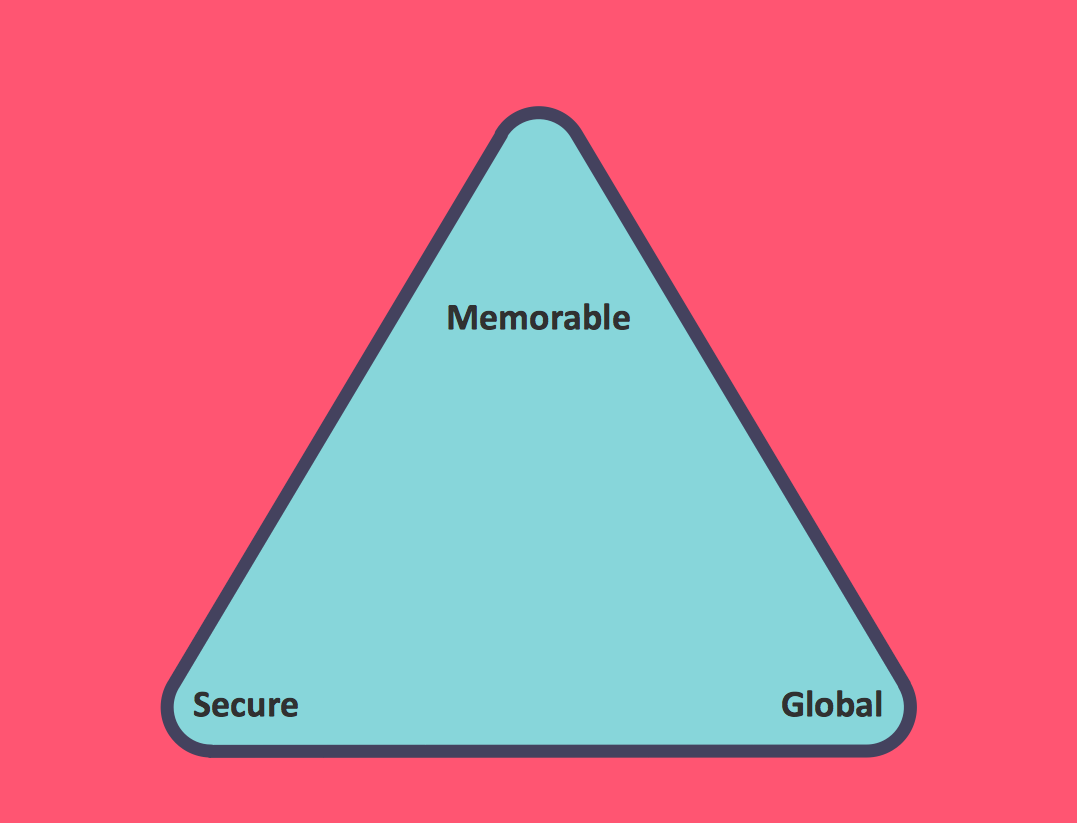
Example 1. Pyramid Diagram. Zooko's-triangle

Talking about useful applications that were all developed for simplifying people’s life, we can mention the ConceptDraw DIAGRAM diagramming and drawing software presented by CS Odessa a few years ago in order to help those who appreciate their time create the needed drawings, such as a Zooko’s triangle diagram.

Taking into consideration all three desirable traits of a network protocol identifier — secure, decentralized and human-meaningful — any ConceptDraw DIAGRAM user can create a Zooko’s triangle diagram within only a few minutes having both ConceptDraw DIAGRAM downloaded on their desktop and ConceptDraw STORE application.

Having the last mentioned product of CS Odessa, you can easily make the needed drawings having the Pyramid Diagrams solution from ConceptDraw STORE — a relatively new product of CS Odessa where a lot of different examples of different drawings can be found as so used as the drafts for your own great looking schemes and plans.

Pyramid Diagram

Example 2. Pyramid Diagrams Solution in ConceptDraw STORE

The Pyramid Diagrams solution include 28 vector shapes all in one stencil library of different colors and design, such as normal pyramid drawings, triangle diagram with circle and arrows, triangle diagram with circles, triangle diagrams with the frames, triangle diagrams with oval in the very middle of it, triangle charts, triangle charts in 3D shape, arrowed block pyramids, funnel diagrams, 3-leveled funnel diagrams, 4-leveled funnel diagrams, 2-leveled 3D pyramid diagrams, 3-leveled 3D pyramid diagrams, 4-leveled 3D pyramid diagrams, 5-leveled 3D pyramid diagrams and 6-leveled 3D pyramid diagrams of different colors.

Having ConceptDraw DIAGRAM drawing application is always a benefit as there are the basic libraries that also can be used for making most of the needed shapes. Thus, if there is a need in making a Zooko’s triangle diagram, you can simply go to the ConceptDraw STORE application finding the so useful Pyramid Diagrams solution to get any of the provided samples of the triangles or you can get those available from the basic libraries within the ConceptDraw DIAGRAM diagramming application.

Having ConceptDraw STORE, though, is a must as long as there is any need in making more than one drawing for work or for some personal needs. Having the Pyramid Diagrams solution enables to create more than 28 design elements that can be found in the only stencil library available to be taken from the Pyramid Diagrams solution and so they can be used being edited if needed as you can always change any of the examples shape, color, design, etc.

Getting the mentioned solution may enable you to create any needed triangle diagrams as well as the pyramids, such as a Zooko’s triangle diagram, mentioning all the needed information easily having the drawings done within only a couple of minutes as all the proposed to the ConceptDraw STORE templates can be always edited and so the great looking triangle diagrams can be created.


See more Pyramid Diagram:


TEN RELATED HOW TO's:
It is easy to recreate any informational system structure using diagrams. There are three main components of any ER diagram: entity, attribute and relationship. Basing on these three components, one can define other, less used elements, such as weak entity or relationship, derived attribute, recursive relationship etc. This is the set of graphic elements of ERD Chen's notation. This ERD notation is used to represent an entity–relationship models. It involves the set of geometric forms: rectangles - depicting entities, ovals - representing attributes and diamonds depicting relationships assigned for first-class objects, that can have relationships and attributes of their own. Connections are displayed with arrowed lines. It is known that the Chen's ERD notation is used to show a detailed view of entities and relationships. ConceptDraw Entity-Relationship Diagram solution from the Software Development section of Solution Park provides the ability to create ERD of database structure for software development purposes using the Chen’s notation elements.Components of ER Diagram *
Picture: Components of ER Diagram
Related Solution:
When thinking about data visualization, one of the first tools that comes to mind is a flowchart design. You can find flowchart symbols, shapes, stencils and icons easily on the Internet, but it might take time to systematize this information. Nevertheless, once you start flowcharting, you’ll love its simplicity and efficiency. This diagram consists from standard flowchart symbols, approved by ANSI (American National Standard Institute) for drawing flowcharts. A flowchart is a diagram that represents a step-by-step algorithm of any process, displaying the process stages as boxes that are connected with arrows. Flowchart design makes it clear and readable. Flowchart designed using ConceptDraw DIAGRAM flowchart software allows to make attractive and clear process presentation, it makes interpretation of the business process flow fresh and versatile. Great flowchart design view is a big advantage over the diagram created manually on a paper.Comparison of bad and good flowchart design showing zigzag flow, crossed connectors, and aligned elements
Picture: Flowchart Design: Principles, Layout, Symbols and Best Practices
Related Solution:
This template shows the Six Markets Model Chart and was included in Marketing Diagrams Solution. It is available from ConceptDraw STORE and can be used as the base for creating your own marketing diagrams.Six Markets Model Chart Template *
Picture: Six Markets Model Chart Template
Related Solution:
If you want to find a way to understand complex things in minutes, you should try to visualize data. One of the most useful tool for this is creating a flowchart, which is a diagram representing stages of some process in sequential order. There are so many possible uses of flowcharts and you can find tons of flow charts examples and predesigned templates on the Internet. Warehouse flowchart is often used for describing workflow and business process mapping. Using your imagination, you can simplify your job or daily routine with flowcharts. Warehouse flowcharts are used to document product and information flow between sources of supply and consumers. The flowchart provides the staged guidance on how to manage each aspect of warehousing and describes such aspects as receiving of supplies; control of quality; shipment and storage and corresponding document flow. Warehouse flowchart, being actual is a good source of information. It indicates the stepwise way to complete the warehouse and inventory management process flow. Also it can be very useful for an inventory and audit procedures.Warehouse Flowchart
Picture: Flow Chart Example: Warehouse Flowchart
Related Solution:
There are many tools to manage a process or to illustrate an algorithm or a workflow. Flowcharting is one of those tools. However, it may be difficult to show complex processes that require multiple attributes or several people in a simple flowchart, so a cross-functional flowchart would be a solution for that situation. To create such flowchart, group processes and steps to labeled rows or columns, and divide those groups with horizontal or vertical parallel lines. It is worth mentioning that there are different types of cross-functional flowcharts, like opportunity or deployment flowchart. This diagram shows a cross-functional flowchart that was made for a trading process. It contains 14 processes, distributed through 5 lines depicting the participants who interact with the process. Also there are connectors that show the data flow of information between processes. The cross-functional flowchart displays a detailed model of the trading process, as well as all participants in the process and how they interact with each other. The lines in the flowchart indicates the position, department and role of the trading process participants.Cross-Functional Flowchart
Picture: Cross-Functional Flowchart
Related Solution:
This sample was created in ConceptDraw DIAGRAM diagramming and vector drawing software using the UML Class Diagram library of the Rapid UML Solution from the Software Development area of ConceptDraw Solution Park. This sample describes the use of the classes, the generalization associations between them, the multiplicity of associations and constraints. Provided UML diagram is one of the examples set that are part of Rapid UML solution.UML Class Diagram Generalization Example<br>UML Diagrams *
Picture: UML Class Diagram Generalization ExampleUML Diagrams
Related Solution:
Perfect charts and graphics diagramming software with rich examples and template. ConceptDraw is ideal to draw Charts and Graphics.Basic Diagramming *
Picture: Basic Diagramming
Related Solution:
Using the Business Diagrams Solution you can create your own professional-looking Venn Diagrams quick and easy.Venn Diagram Example - 3 Circle Venn Diagram
Picture: 3 Circle Venn Diagram. Venn Diagram Example
Related Solution:
When trying to figure out the nature of the problems occurring within a project, there are many ways to develop such understanding. One of the most common ways to document processes for further improvement is to draw a process flowchart, which depicts the activities of the process arranged in sequential order — this is business process management. ConceptDraw DIAGRAM is business process mapping software with impressive range of productivity features for business process management and classic project management. This business process management software is helpful for many purposes from different payment processes, or manufacturing processes to chemical processes. Business process mapping flowcharts helps clarify the actual workflow of different people engaged in the same process. This samples were made with ConceptDraw DIAGRAM — business process mapping software for flowcharting and used as classic visio alternative because its briefly named "visio for mac" and for windows, this sort of software named the business process management tools. This flowchart diagram shows a process flow of project management. The diagram that is presented here depicts the project life cycle that is basic for the most of project management methods. Breaking a project into phases allows to track it in the proper manner. Through separation on phases, the total workflow of a project is divided into some foreseeable components, thus making it easier to follow the project status. A project life cycle commonly includes: initiation, definition, design, development and implementation phases. Distinguished method to show parallel and interdependent processes, as well as project life cycle relationships. A flowchart diagram is often used as visual guide to project. For instance, it used by marketing project management software for visualizing stages of marketing activities or as project management workflow tools. Created with ConceptDraw DIAGRAM — business process mapping software which is flowcharting visio alternative or shortly its visio for mac, this sort of software platform often named the business process management tools.Process Flowchart
Picture: Process Flowchart: A Step-by-Step Comprehensive Guide
Related Solution:
A flowchart is a simple but very functional tool when it comes to understanding a workflow or to removing unnecessary stages from a process. When drawing flowcharts, keep in mind that there are four common types of flowcharts, like document flowcharts and data flowcharts that show control over a data or document flow over a system. To show controls on a physical level, use system flowcharts. In addition, to show controls in a program, you can draw a program flowchart. This flowchart diagram represents the piece of an article editing process, that involves the author and editor. It was created using the Basic Flowchart notation that consists from the basic flowchart symbols. The start and the end of the process are indicated with "Terminator" symbols. The "Process" symbols show the action steps consisting from making edits and searching for a compromise, when the author does not agree with the suggestions of the editor. The "Process" symbol is the general symbol in process flowcharts. The "Decision" symbol indicates a branching in the process flow. There are two branches indicated by a Decision shape in the current flowchart (Yes/No, Disagree/Agree). This basic flowchart can be used as a repeating unit in the workflow diagram describing the working process of some editorial office.Types of Flowcharts *
Picture: Types of Flowcharts
Related Solution:
ConceptDraw
DIAGRAM 18