Pyramid Diagram
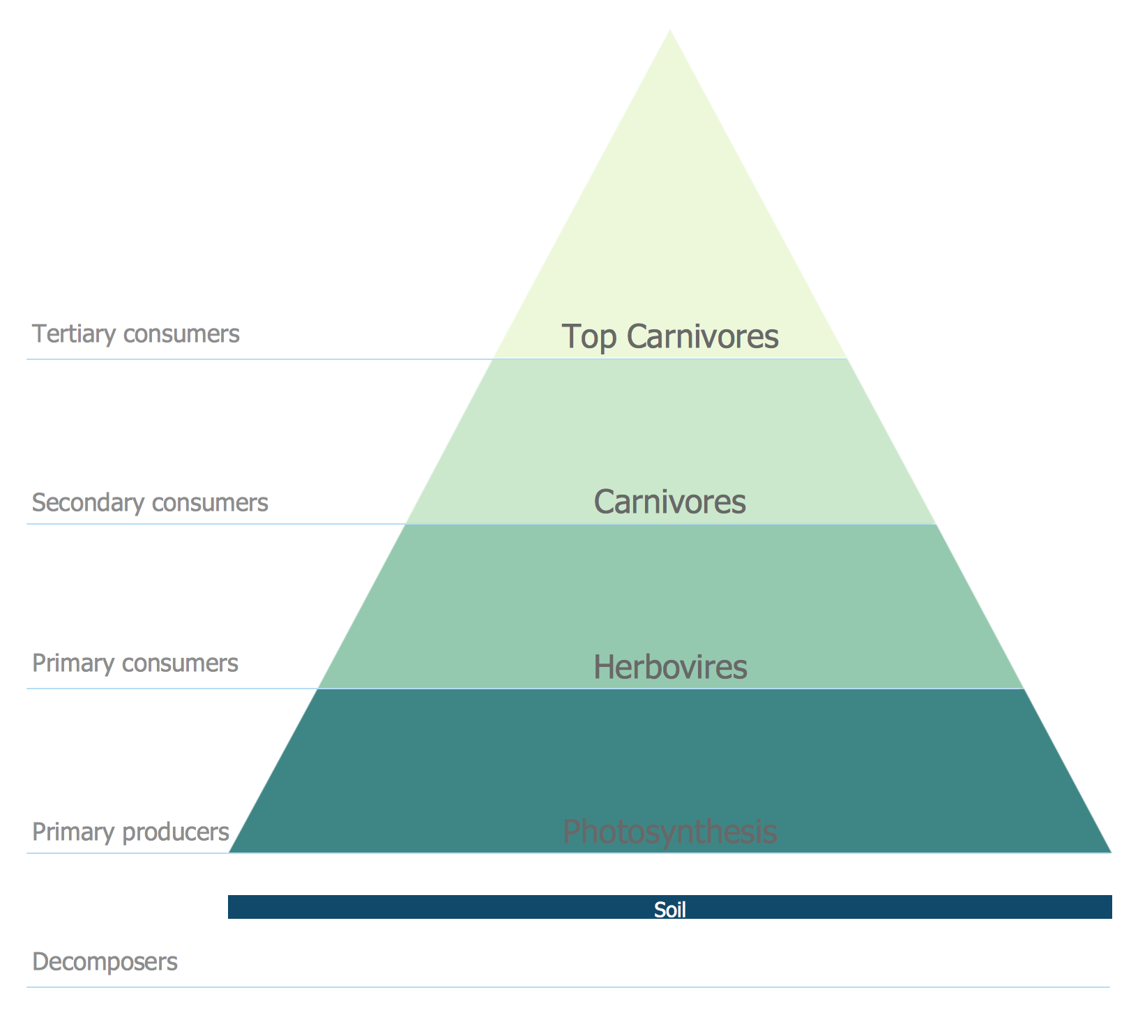
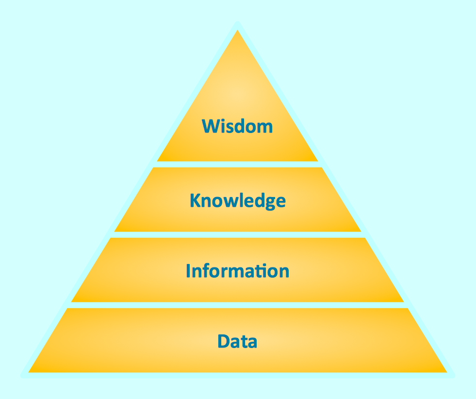
Knowledge Pyramid - Triangle Diagram
The DIKW pyramid has other names and it is also known as the DIKW hierarchy, the wisdom hierarchy, the information hierarchy, the data pyramid and the knowledge hierarchy. Such pyramid refers to a class of models and it is used for representing the purported structural and functional relationships between information, data, wisdom and knowledge. At the same time, the term “information” can be defined in terms of data, when the term “knowledge” is defined in terms of information and the term “wisdom” — in terms of knowledge. Not all the versions of the DIKW hierarchy reference all the four components, as some include more components, additionally.
Any DIKW model can be also characterized as a chain, as a continuum, as a framework and as a series of graphs, often being quoted in definitions of data, knowledge and information in the so called “information management”, as well as knowledge management and information systems literature. At the same time, it is important to remember that there has been a limited direct discussion of the hierarchy so far. Although, there is still no consensus as to the definitions used in the model, it still has led the Israeli researcher Chaim Zins to suggest that all the components of DIKW, which are known to be “data, information and knowledge”, refer to a class of at least five models, as a function of whether information, knowledge and data are each conceived of as objective, subjective or both. In his theory, the objective and subjective are not related to truthfulness and arbitrariness, which are the terms being usually attached to the concepts of the so called “objective” as well as the “subjective” knowledge.
Data in the context of DIKW is a group of signs or symbols, with help of which it is simpler to represent the needed signals or stimuli, being sometimes understood to be referred not only to symbols, but also to signals or stimuli referred to by said symbols, termed as the so called “subjective data”. The term of the “universal data” can be simply understood as a “product of observation". Also, data can be characterized as the objective, discrete, unorganized and unprocessed observations or facts, having no value or meaning for a reason of a lack of any proper interpretation and context. Data can be also simply defined as the "merely raw facts". When such facts have as some fundamental property then they are known to be true, having an objective reality. Otherwise, they can be verified, resulting in being defined as “false”: nonsensical and meaningless data from the “DIKW model”.
The so called “subjective data can be comparable to the so called “knowledge by acquaintance”, being based on the direct experience of such “stimuli”. No matter which of the definitions of data is chosen, any data can be consistently defined including sets of signs used for representing the so called “empirical stimuli or perceptions of a property of an event, an object or of the environment", or "symbols". In this sense data is known to be recorded, which means storing the captured symbols, including words, numbers, images and diagrams.
Making diagrams is always much simpler having the proper software, such as ConceptDraw DIAGRAM diagramming and drawing one. Having a choice of so many different applications nowadays, it is always better to choose the right one, meaning to choose the best one. At least one of the best and most commonly used is a ConceptDraw DIAGRAM one. The mentioned software is the one being used by people in the world, working for completely different organizations being involved in many different spheres of the existing business activity.
Thus, working for IT company or being involved in the university activities, providing the affordable education in terms of it being simple enough for students to understand it easily from the very first lectures, it is better to use the progressive software, such as ConceptDraw DIAGRAM one, for enabling those who are the target audience to understand information of any complexity in a way of arranging the existing data in a way of the drawing, creating it in the mentioned application.

Example 1. Pyramid Diagrams Solution in ConceptDraw STORE
To represent any needed data with help of ConceptDraw DIAGRAM diagramming and drawing software is always much simpler as it consists of the basic tools, such as the stencil libraries full of design elements to make it possible to make the needed information to be understood much faster in a better and more convenient way — illustration. You can always download the mentioned application from this site, as well as another product of CS Odessa — ConceptDraw STORE. Having the mentioned tools will enable you to make your drawings only within a couple of hours (sometimes — minutes), but the time always depends on the complexity of the drawing itself.
Example 2. Knowledge Puramid. Knowledge hierarchy triangle diagram
Nevertheless, you can always be sure that using the needed solution from ConceptDraw STORE while working in ConceptDraw DIAGRAM diagramming and drawing application will speed the work up as having such solution, as the “Pyramid Diagrams” one means having all the necessary tools for creating any needed pyramid diagram (for example, a knowledge triangle diagram). Enabling yourself to make a very smart and professionally looking drawings, such as Pyramid Diagrams is simple: all you need is to download a ConceptDraw DIAGRAM diagramming and drawing application from this site, then to get another product of CS Odessa, developed by the IT specialists for making it possible to make the needed drawings within a short period of time, and so to use at least one of the solutions available for all the ConceptDraw DIAGRAM users, such as, for example, a “Pyramid Diagrams” one, consisting of the previously created examples of the Pyramid Diagrams, which all can be used as drafts for your own great looking drawings, ensuring all the ConceptDraw DIAGRAM users in getting a very sophisticated result.
See more Pyramid Diagram:
- Zooko Triangle Diagram
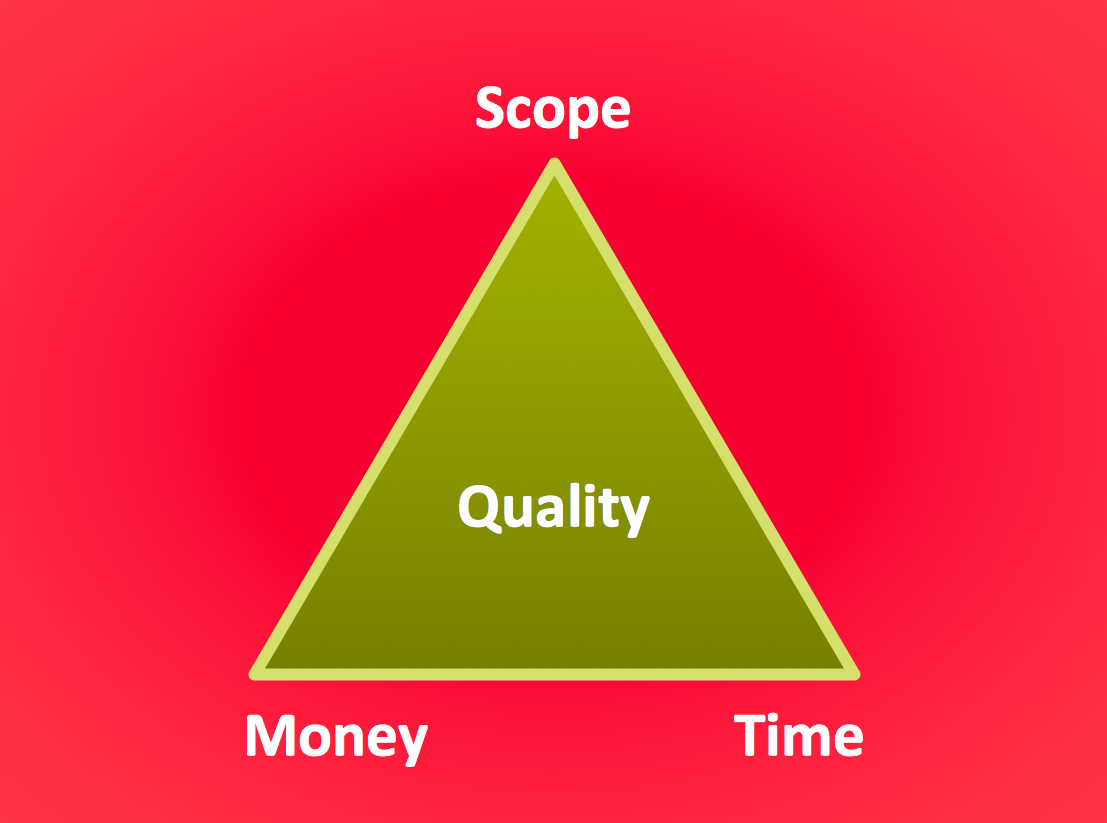
- Time, Quality, Money Triangle Diagram
- Project Triangle Diagram
- Purchase Funnel Diagram
- Project Triangle Chart
- Priority Pyramid Diagram
- Organization Triangle Diagram
- Knowledge Triangle Diagram
- Triangular Graphic
- Inverted Pyramid
- Fundraising Pyramid
- 3D Triangle Diagram
- DIKW Pyramid
- Five level pyramid model
- Four level pyramid model
- Three level pyramid model