Pyramid Diagram
Project Triangle
Those triangles within any technical analysis are known to be the chart patterns that can be commonly found in the price charts of the financially traded assets, such as stocks, futures, bonds, etc. The pattern is known to be deriving its name from the fact that it is characterized by some contraction in a price range being the converged trend lines, giving it a triangular shape.
Triangle patterns are known to be broken down into three different categories: the ascending triangle, the symmetrical triangle and the descending triangle. While the shape of the triangle is significant, the direction of more importance that the market moves when it breaks out of the triangle. While the triangles are known to be sometimes reversing its patterns — meaning reversing the prior trend — they can be normally seen as the continuation patterns meaning the continuations of the prior trends.
The Project Management Triangle is one of the most popular and widely used drawings to make by using the ConceptDraw DIAGRAM diagramming and drawing application that enables to edit the already existing, the pre-made templated of the triangle charts from the Pyramid Diagrams solution of ConceptDraw STORE application – another very useful product of CS Odessa that was developed especially for a reason of providing all the ConceptDraw DIAGRAM users with the so much needed stencil libraries full of the design symbols as well as the professionally created layouts.
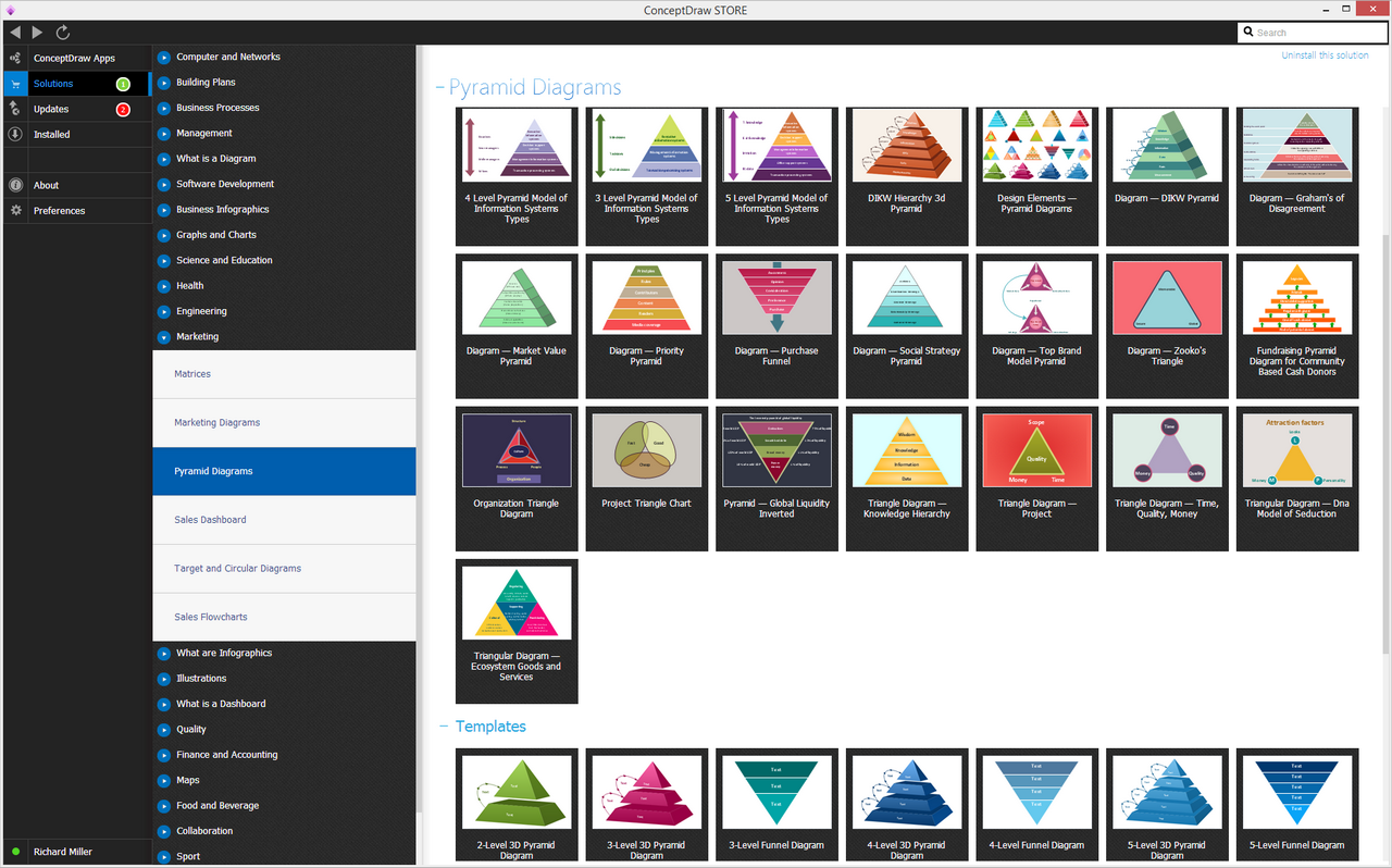
Example 1. Pyramid Diagram Solution in ConceptDraw STORE
Known to be also called as the Triple Constraint, "Project Triangle" and Iron Triangle, a triangle chart that is still most commonly known to be called as a “Project Management Triangle”, is a well-known model of the constraints within a project management activity. For a reason of its origins being unclear, such triangle chart has been used since the 1950s at least, contending that the quality of work should be constrained by the project's budget, the scope (meaning the features) and the deadlines.
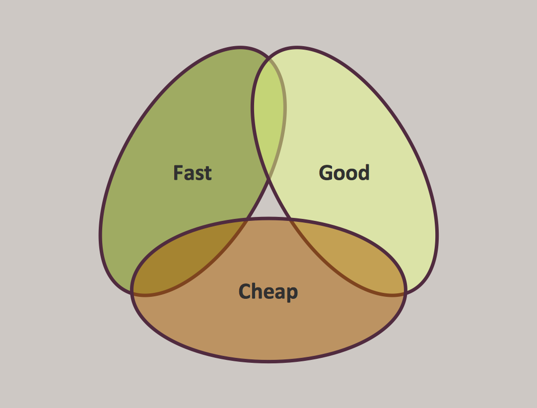
Example 2. Pyramid Diagram. Project management triangle chart
Any project manager can trade between the previously mentioned constraints within a triangle chart. Any changes in one of the constraints may lead to the other changes appearing in the other in order to compensate the quality that may suffer. Thus, any project can be completed much faster by cutting its scope or increasing its budget. That is why increasing the scope may require the equivalent increases in both schedule and budget. Cutting a part of a budget without adjusting either the scope or the schedule may lead to lowering the quality.
Although, any trading between different constraints may sometimes not be possible. As an example, any project manager may suggest throwing money or/and at a fully staffed project which may simply slow it down. Also, in the poorly run projects, it may be often possible to improve schedule, scope or budget, without adversely affecting the quality itself.
The Project Management Triangle can be also used for analyzing different projects. Being misused for defining the success at a reasonable quality within the established budget and schedule, it still may be insufficient as a model of a project success omitting the crucial dimensions of success, such as an impact on the stakeholders, user satisfaction and learning.
The time constraint can refer to the amount of all the time that is available for completing some a project. The cost constraint can refer to the budgeted amount that is known to be available for the project. The scope constraint can refer to what has to be done in order to produce some project's end result. All three constraints can be often competing ones as the increased scope usually mean the increased cost and increased time, a tight time constraint may mean the increased costs as well as the reduced scope, and not enough budget may lead to increasing the time and reducing the scope at the same time.
The discipline of any project management is known to be providing the needed techniques and tools that enable all the members of the project team to organize their work in order to meet the mentioned constraints. There is another approach that can be used within a project management: to consider all three constraints to be finance, human resources and time.
Thus, in case some job has to be done in a shorter time, then surely more people may be involved in solving some particular problem, but in return it will raise the cost of the project overall. But, also, it is still possible to do this task quicker by reducing the costs elsewhere in the project by some equal amount.
As a project management graphic aid, making a triangle can help you show both resources and technical objective, as well as time as the sides of one triangle, instead of its corners. The distance between the inner and outer triangles can illustrate the contingency or the hedge for each of the mentioned three elements.
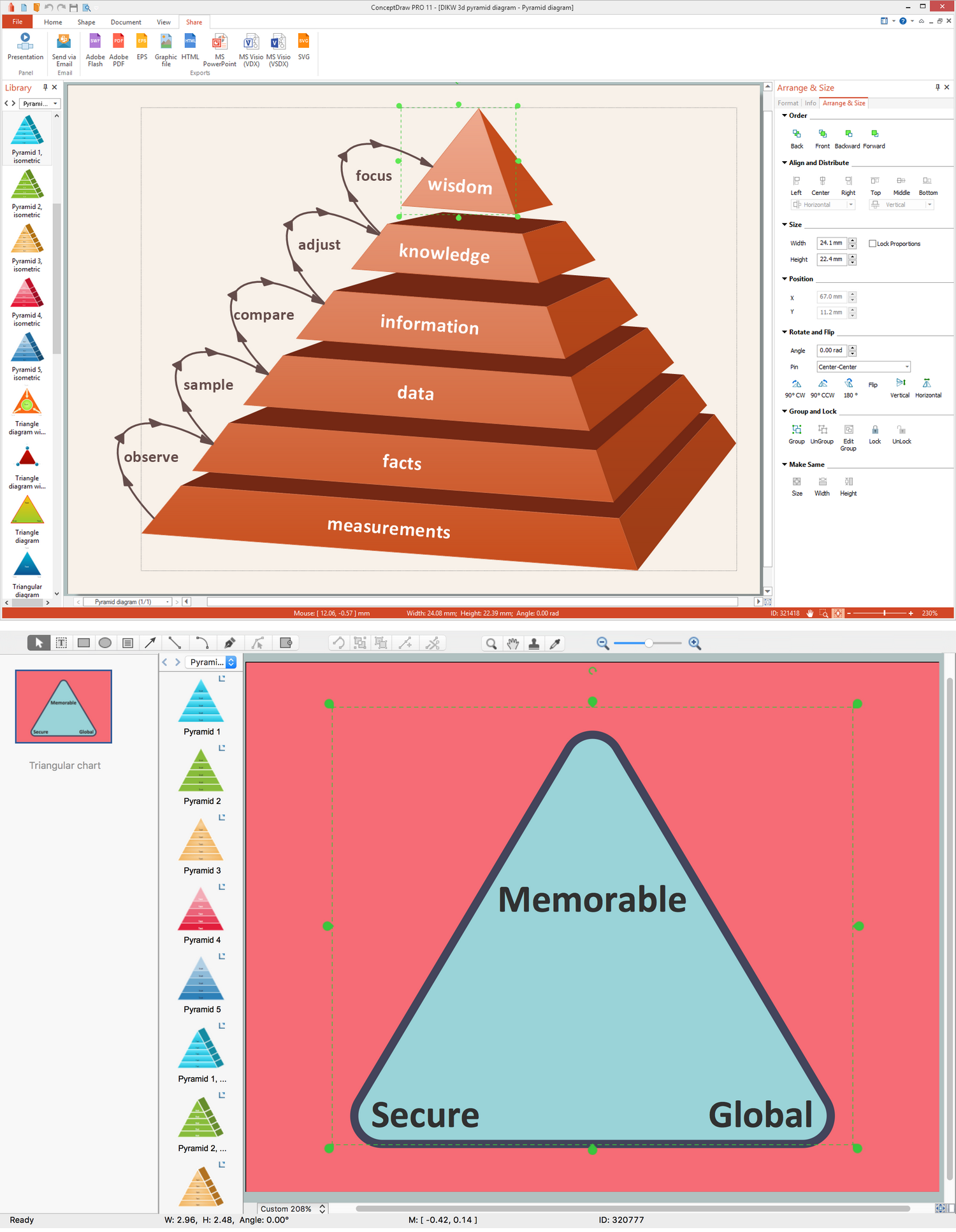
Example 2. Pyramid Diagram in ConceptDraw DIAGRAM
The real value of any project triangle that can be always created with the help of ConceptDraw DIAGRAM diagramming and drawing software is to show the complexity that is known to be present in any of the projects. The plane area of the triangle is the one representing the nearly infinite variations of different priorities that can exist between the already described three competing values. Knowing the limitless variety, using this graphic aid can facilitate making much better project decisions as well as project planning, ensuring the alignment among all the team members as well as the project owners.
A term “scope” within the project management might need the requirements that were previously specified for achieving some that much-needed end result. The overall definition of what the project is expected to accomplish as well as some specific description of what the end result should be may lead to the needed results. And using the right drawing tool such as a ConceptDraw DIAGRAM one may guarantee the needed outcome.
See more Pyramid Diagram:
- Zooko Triangle Diagram
- Time, Quality, Money Triangle Diagram
- Project Triangle Diagram
- Purchase Funnel Diagram
- Project Triangle Chart
- Priority Pyramid Diagram
- Organization Triangle Diagram
- Knowledge Triangle Diagram
- Triangular Graphic
- Inverted Pyramid
- Fundraising Pyramid
- 3D Triangle Diagram
- DIKW Pyramid
- Five level pyramid model
- Four level pyramid model
- Three level pyramid model