Fully Connected Network Topology Diagram
Fully Connected Network Topology Diagram
Computer network diagrams are well known to those who deal with making such diagrams every day or at least once a month. They can be LAN topology diagrams, Logical Bus with a physical star, network topology diagrams, network architecture diagrams, physical LAN topology diagrams, regional cable head-end diagrams, wireless router network diagrams and others. All of the examples mentioned above and many more other network diagrams, including the fully connected network topology diagrams, can be found on this site as well as in ConceptDraw STORE, which is an application to ConceptDraw DIAGRAM software, including the solutions for using as the useful tools for drawing different kinds of the diagrams as well as charts, flowcharts and plans, maps and schemes.
Talking about the fully connected network diagram, we should mention, that the fully connected network itself can be called a complete topology or a full mesh topology and it is simply a network topology, in which there’s a direct link between all of the pairs of its nodes. In such fully connected network, which includes the n nodes, there are always n(n-1)/2 direct links.
Networks designed with the use of such topology are frequently very expensive to set up, but they always provide a high degree of reliability as there are so very many paths for data, that is provided by the large number of redundant links between nodes. This type of the existing topologies is mostly seen in military applications, but you can use it for your own very different purposes, as it is never a problem to find the application to the great looking network topology diagram, well created by yourself.
Dealing with the need of making different diagrams time to time, working in IT company or somewhere else as an IT specialist, you might wonder where to find the software which can be useful both for making drawings from a scratch as well as making all of these drawings using already previously made samples.
Saving your time and so your money can be done with ConceptDraw DIAGRAM software as it is one of only a few similar (but still not as good) applications, as it allows to get all those that much needed samples and templates of already created charts, flowcharts, diagrams, schemes, plans and matrices by professionals who know very well what exactly should be done to the drawings, analogically to the fully connected topology diagram, so they look simply great.
The CS Odessa team of IT professionals, knowing all about the drawings and so the applications existing for the purpose of making such tables and schemes, have developed this unique software, which can change your life completely by offering the already previously made schematics, which you can always use as your drafts and so end up having a very good looking and smart drawings within only a couple of minutes.
In case you have enough experience being able to make one of a couple of such diagrams within a short period of time, then you can use ConceptDraw DIAGRAM software as only a tool for making those diagrams from the very scratch. Once you need some help in making your first diagrams, for example, or you don’t have as much time for creating everything from the very beginning, then the samples we provide can be very useful for you.
ConceptDraw DIAGRAM software is a very unique tool and it is very popular for a reason: because it allows to make any needed drawing within only a couple of hours or even a couple of minutes, as having the solutions and so the templates and stencils made by those, who know a lot about such kinds of drawings, is always beneficial.
Downloading ConceptDraw DIAGRAM software allows you to get ConceptDraw STORE as another application, which can be used for downloading any needed solutions full of the needed stencils as well as great looking templates. Each of the providing solutions include the stencil libraries (at least one) and pre-made samples, available for ConceptDraw DIAGRAM software users any time they want to use them.
That unique feature of this software attracts lots and lots of users from all over the world, especially those people, who deal with drawings similar to this one all the time, working on their laptops and computers creating great looking plans, charts, flowcharts, diagrams and maps. This software can be also very useful for those who do not know as much about using the drawing applications as we always provide the users of ConceptDraw DIAGRAM with the needed support as well as the needed advices.
You can find so many of the written articles describing all of the elements of our application as well as how to use it in the best and the most rational way on this site. You can also find so many videos, which were made for the same purpose – to explain how to make the best drawings using this software. If you still have questions left after checking for what you need here, on this site, then we will be happy to help you via our support centre.
But first of all, we recommend to download the solution named “Computer and Networks”, which can be found in Computer and Networks area of ConceptDraw Solution Park and which contains a set of examples, templates and vector design elements of fully connected network topology and other network diagrams, so you can create yours only in a couple of hours, or even minutes, depending on your experience in using ConceptDraw DIAGRAM
This Computer and Networks solution provides examples and templates as well as vector stencils library with symbols of local area network (LAN) and wireless LAN (WLAN) equipment. You can use it in order to draw the physical and logical network topology diagrams for wired and wireless computer communication networks.

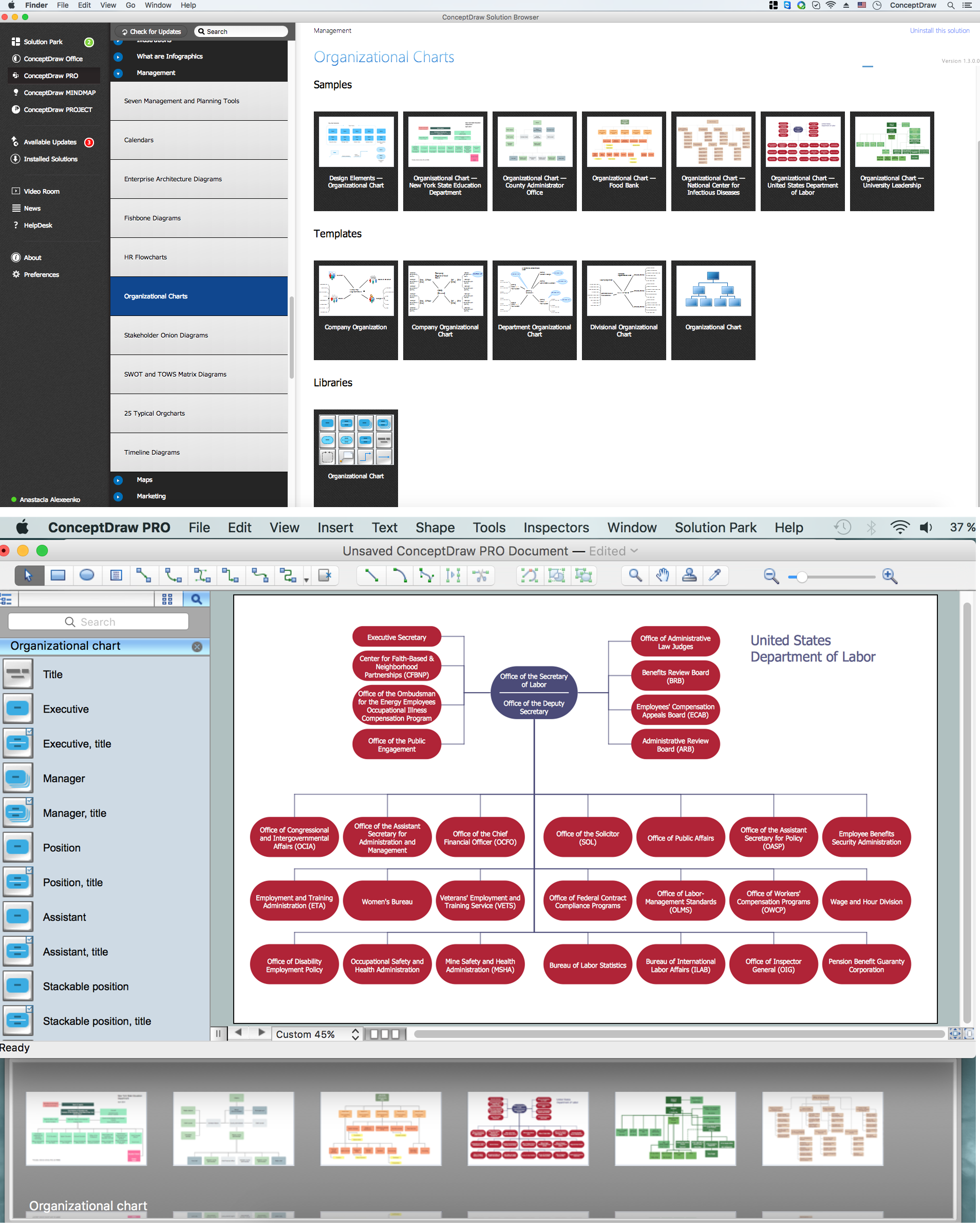
Pic. 1 Computer and Networks area
Those, who face the need of making different kinds of diagrams, including the fully connected network topology ones, will find ConceptDraw DIAGRAM software as well as its solution very useful. Especially the Computer network engineers and web designers will like it as they are those specialists who need to illustrate the network documentation in a way of computer network diagrams time to time. They all will find this ConceptDraw DIAGRAM application very convenient as it is simple, but professional, smart and sophisticated.

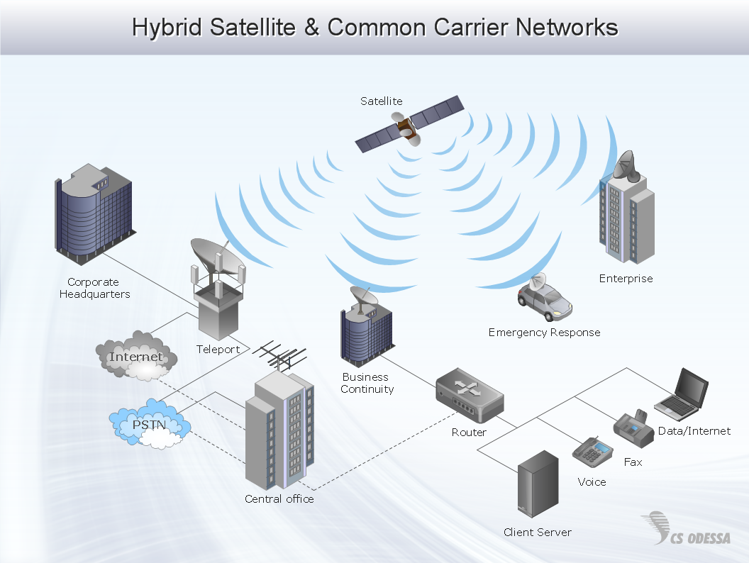
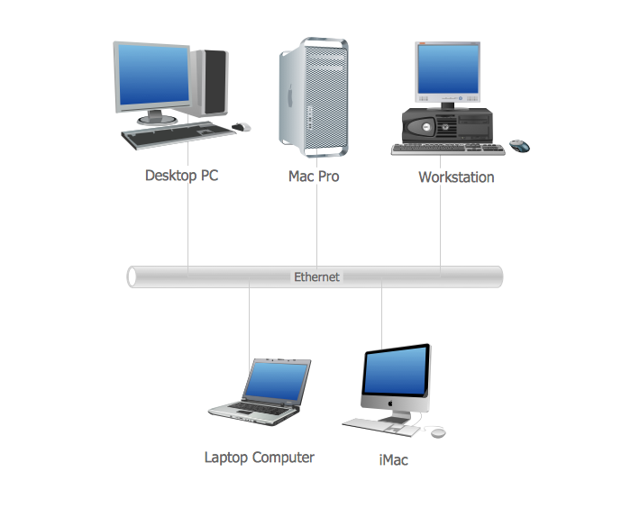
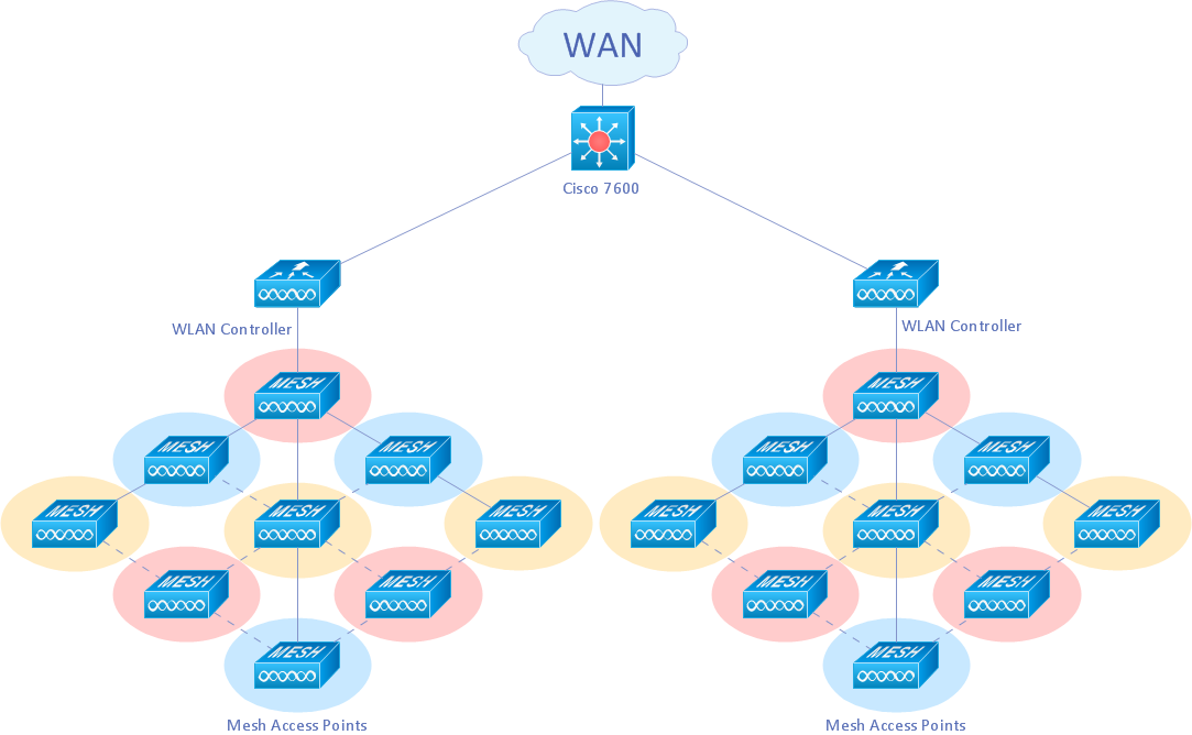
Pic. 2 Fully Connected Network Topology
Use it to draw the physical and logical network topology diagrams for wired and wireless computer communication networks.

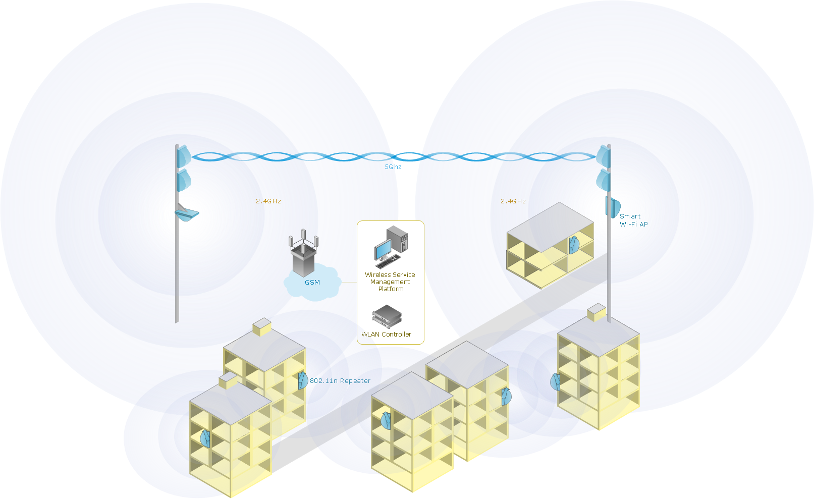
Pic. 3 Fully Connected Network Topology Diagram
Fully connected network
"A fully connected network is a communication network in which each of the nodes is connected to each other. In graph theory it known as a complete graph. A fully connected network doesn't need to use switching nor broadcasting. However, its major disadvantage is that the number of connections grows quadratically with the number of nodes, per the formula
c=n(n-1)/2,
and so it is extremely impractical for large networks. A two-node network is technically a fully connected network." [Network topology. Wikipedia]
Intended for Computer network engineers and designers who need to illustrate the network documentation with computer network diagrams.
See Also Network Topologies:
- Bus Network Topology
- Star Network Topology
- Ring Network Topology
- Mesh Network Topology
- Tree Network Topology