Mesh Network Topology Diagram
Network Topology Diagram
Talking about a mesh network, it would be fair to say that it is a network topology, where the nodes can be found, each of which relays data for the network. All of these mesh nodes co-operate in the distribution of data in the same network. Such topology can be applied to both wireless and wired networks, but the wireless mesh networks can be considered as a type of so-called “wireless ad hoc network”. In these circumstances, the wireless mesh networks are related much closer to the mobile ad hoc networks (MANETs). Although MANETs are not restricted to a specific mesh network topology. Wireless ad hoc networks or MANETs can take any form of network topology and so they can be used in this way.
Mesh networks can relay messages using a so-called “routing technique”, or sometimes a “flooding technique”. In the first case the message is propagated along a path by hopping from one node to another until it reaches the planned destination. To make sure that all the paths are available, this network must allow the continuous connections as well as reconfigure itself around the broken paths, using self-healing algorithms (for example, “Shortest Path Bridging”). Such “self-healing” allows a routing-based network to be able to operate in case a node breaks down or when a connection becomes unreliable. Finally, the network becomes quite reliable, as there is often more than one path between a destination in the network and a source itself. This very concept is commonly used in the wireless situations and it can also be applied to the wired networks as well as to the software interaction.
Such mesh network, which nodes are all connected to each other, is known as a “fully connected network”: the wired ones have the advantages of reliability and security: the problems in a cable affect only two nodes attached to it. Usually in such networks the number of cables, and so the cost, goes up very rapidly once the number of nodes increases.
Wired mesh radios allow the Ethernet switches to connect the mesh topology and so all of the paths to be active. And the wireless mesh radios are very different from Wi-Fi ad hoc, as they primarily support voice rather than desktop or software computing. A radio device is different from a smart phone or computer, as the latter is programmable and has multi-function compute capability. Such wireless mesh radio networks were developed from the very beginning for a purpose of using them in the military applications. But since then their size, cost as well as the power requirements of radios have declined, which enabled the multiple radios to be contained within a single mesh node, and so to allow greater modularity. Nowadays each can handle the multiple frequency bands and support different functions once it is needed, for example: client access, backhaul service, scanning, etc.
Early wireless mesh networks all used nodes which have a single “half-duplex” radio that can receive or transmit, but not both at the same time. This requires a so-called “shared mesh” configuration, which means the wireless mesh network configuration that uses a single radio to communicate with the help of the “mesh backhaul links” to all the closest nodes in the mesh. Some time later the wireless mesh networks started to use the nodes with more complex radio hardware, enabling to receive the packets from an upstream node and transmit these packets to a downstream node simultaneously, which is a prerequisite for a so-called “switched mesh” configuration, being the wireless mesh network configuration that uses multiple radios to be able to communicate with the aid of dedicated mesh backhaul links to each neighbouring node in the mesh.
As an example of the mesh network, we can mention SMesh, which is an 802.11 multi-hop wireless mesh network that was developed by the “Distributed System and Networks Lab” at “Johns Hopkins University”. A fast handoff scheme allows the mobile clients to roam in the network without any interruption in their connectivity. There are also many mesh networks operate across multiple radio bands. For instance, “Firetide and Wave Relay mesh networks” have a chance to communicate each node to another node on 5.2 GHz or 5.8 GHz. The so-called “SolarMESH project” examined the potential of powering mesh networks, which was based on 802.11, using rechargeable batteries as well as solar power. Legacy 802.11 access points were found to be inadequate due to the requirement that they had to be continuously powered. There was another so-called “WING project”, sponsored by the “Italian Ministry of University and Research”. It was led by “CREATE-NET” as well as “Technion” which developed a set of novel protocols and algorithms to make it possible for the wireless mesh networks access the architecture for the next generation Internet. “WiBACK Wireless Backhaul Technology” has been developed by the “FOKUS” in Berlin: the networks, being powered by solar cells and designed especially to be able to support all of the existing wireless technologies, were rolled out to several countries in sub-Saharan Africa in 2012.
The recent standards for wired communications have also incorporated the concepts from Mesh Networking. As an example, it is interesting to analyse the ITU-T G.hn, which is a standard specifying a high-speed local area network using existing home wiring, such as phone lines, coaxial cables and power lines. In the noisy environments, like the power lines, where signals can be heavily corrupted as well as attenuated by noise, it is common for the mutual visibility between devices in a network to not be complete. In such situations, one of the nodes has to act as a relay and so to forward the messages between the nodes which cannot communicate directly, creating a so-called "relaying" network.
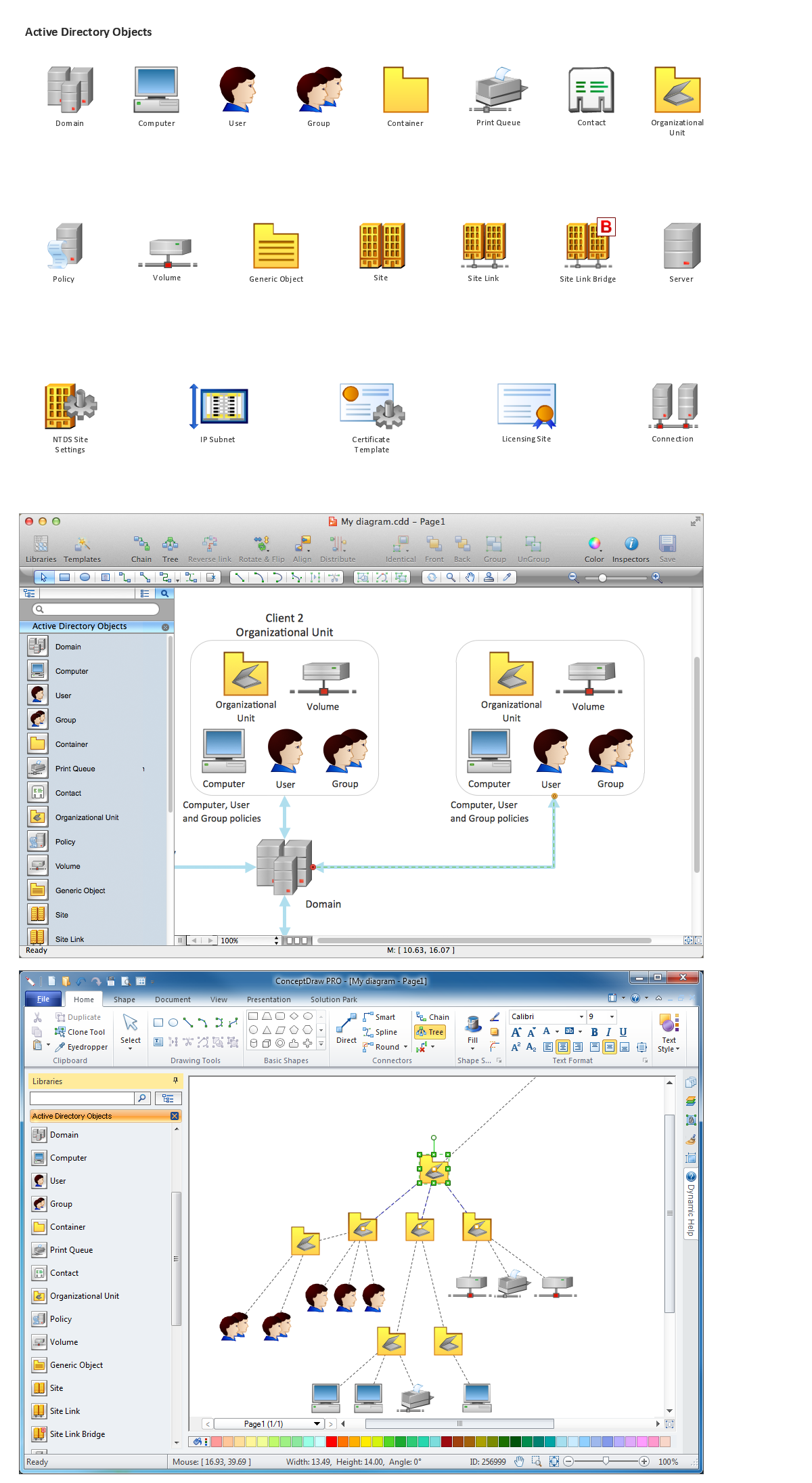
Once you decide to use the mesh network topology for your diagrams, then you can always create all of the needed schematics using ConceptDraw DIAGRAM software. Using ConceptDraw STORE as another product of CS Odessa, developed for storing the solutions full of the necessary tools, is only a benefit for you and so your drawings, in order to get a great looking as well as a professional result. The “Computer and Networks solution” can be found in the “Computer and Networks area” of “ConceptDraw Solution Park” and it provides all the needed examples and templates of pre-made diagrams as well as the vector stencils library with design symbols of wireless LAN (WLAN) and local area network (LAN) equipment.

Pic. 1. Mesh Network Topology Diagram solution
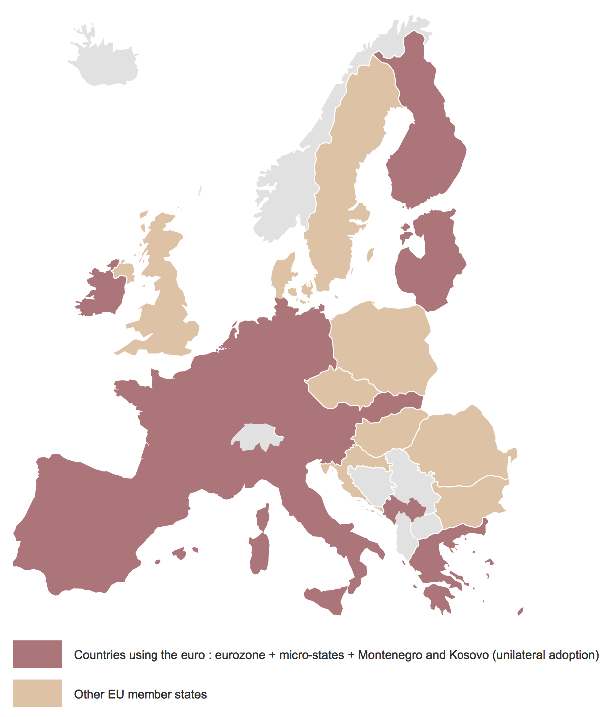
Use it to draw the physical and logical network topology diagrams for wired and wireless computer communication networks.

Pic. 2. Mesh Network Topology
This example was created in ConceptDraw DIAGRAM using the Computer and Networks Area of ConceptDraw Solution Park and shows the mesh network topology diagram.

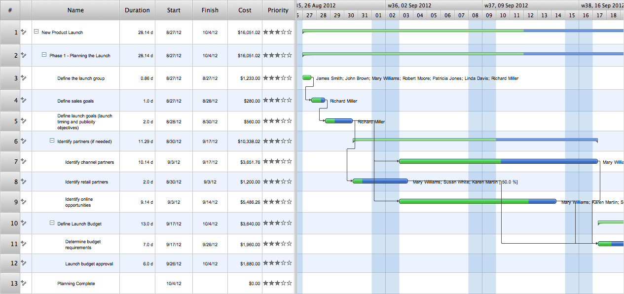
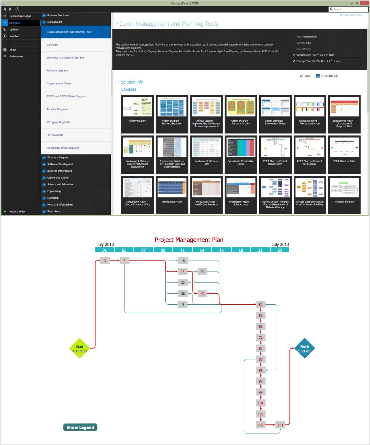
Pic. 3. Mesh Network Topology Diagram
"Wireless mesh networks were originally developed for military applications. Mesh networks are typically wireless. Over the past decade, the size, cost, and power requirements of radios has declined, enabling multiple radios to be contained within a single device, i.e., mesh node, thus allowing for greater modularity; each can handle multiple frequency bands and support a variety of functions as needed-such as client access, backhaul service, and scanning (required for high-speed handoff in mobile applications) — even customized sets of them.
Work in this field has been aided by the use of game theory methods to analyze strategies for the allocation of resources and routing of packets." [Mesh networking. Wikipedia]
See Also Network Topologies: