Ring Network Topology
Ring Network Topology Diagram
A network topology in which each of the nodes connects to two other nodes, resulting in forming a continuous pathway for the signals through each of the nodes known to be called the “rings”, is known to be called as a “ring network”. Data within such networks is known to be traveling from one node to another node, through all the nodes one by one along its way handling every single packet. The mentioned “rings” can be “unidirectional”, having all its traffic travelling clockwise or anticlockwise all the way around the ring. Also, it can be the so called “bidirectional”, providing only one single pathway between two nodes out of many other nodes. A unidirectional ring network is known to be very likely disrupted by the failure of some link appearing to be nearby.
A node failure as well as any cable break may lead to isolation of every single node, which is attached to the “ring”. Some of the ring networks are known to be adding a so called "counter-rotating ring", also known to be called a “C-Ring”. Adding the mentioned ring can be done for forming a redundant topology. Thus, once break happens, a data may get wrapped back on the ring before it reaches the end of the cable. Such data is known to be maintaining a path to every single node all the way along the resulting counter-rotating ring.
The "dual ring" networks are known to be including the so called “Spatial Reuse Protocol”, as well as the “Fiber Distributed Data Interface”, or “FDDI”, and the “Resilient Packet Ring”. The well-known “IBM token ring networks” are also sometimes called as the “802.5 networks”. They are commonly used for avoiding all the possible and existing weakness of a ring topology by using another topology — a “star” one. Such mentioned topology is usually used at the physical layer for imitating a ring at the so called “data link layer”.
Some of the previously mentioned “SONET/SDH rings” have two sets of the bidirectional links, which can be found between the nodes, allowing the failures or maintenance at the multiple points of the same ring resulting in no loss of the primary traffic on the outer ring in a way of switching the traffic on the inner ring after the so called “failure points”.
One of the advantages of using such network topology can be mentioned the convenience of using it for performing in a better way than a bus topology does, especially in the cases of the need of loading under the so called “heavy network”. The mentioned network topology is known to be used within a very orderly network having every device accessing to the “token” having the opportunity to transmit. Such ring network topologies do not require any central nodes for managing the connectivity between different computers. Because of such point to point line configuration of devices with a device on another side, it is quite simple to install as well as to re-configure whatever is needed by removing or adding any device.
Another special feature of the ring network topologies is its “point to point” line configuration, which makes it much simpler to isolate all the previously identified faults. Also, the reconfiguration for line faults of bidirectional rings in ring network topology can be very fast, having all the switching happening at the highest level, leading to the traffic not requiring any individual re-routing.
The disadvantages of the ring network topology: first of all, it is always more difficult to configure using it to compare to using a “star” one as any node adjunction equals to the ring reconfiguration and shutdown. One of the malfunctioning workstations within the ring network topology can create lots of problems for all the network. This can be solved by using a switch or a dual ring used for closing off the break. Every time there’s some moving, changing and adding the devices can affect the entire ring network and the communication delay is known to be directly proportional to the number of all the existing nodes in the ring network.
It is important to remember that any ring network may afford the so called “fault tolerance” to the telecommunication network having two paths between any two nodes on the network. Ring protection is known to be a system commonly used for assuring any needed communications, continuing in the event of failure of only one path. The most widely used protection architectures are “1+1” as well as “1:1”.
In 1+1 architecture, every single protection path is known to be used for protecting the signal having the bridge at the head of the path on a permanent basis, while the switching occurs at its tail end. There are more than two parallel routes are sent in this architecture traffic and the receiving end is known to be selecting the better of the mentioned two signals. Once some failure occurs, the destination switches into one of the alternative paths. The mentioned architecture is quite a widely used for as it is simple for implementing, resulting quite fast restoration. Although, there’s still a drawback, which is the wastage of the bandwidth, occurring for a reason of no traffic traveling through the redundant path.

Pic. 1. Ring Network Topology
Drawing the ring network topology diagrams taking into consideration any of the mentioned architectures can be always much simpler using a professional software for completing such tasks. One of the best applications nowadays is ConceptDraw DIAGRAM one, enabling all its users to create a great looking diagram, such as a ring network topology one, especially having the Computer and Networks solution downloaded from ConceptDraw STORE application.

Pic. 2. Ring Network Topology Diagram
Having the ConceptDraw DIAGRAM software means having all the needed tools for making smart looking drawings, at the same time having the ConceptDraw STORE which is meant to be used while working in ConceptDraw DIAGRAM means simplifying your work with creating such diagrams by using the previously developed solutions full of the stencil libraries with the design symbols depending on the subject of your drawing.
See Also Network Topologies:
- Bus Network Topology
- Star Network Topology
- Mesh Network Topology
- Tree Network Topology
- Fully Connected Network Topology
TEN RELATED HOW TO's:When we think about programming, we usually imagine sleepless nights spent on writing kilobytes of code. However, from another point of view, Software development with ConceptDraw DIAGRAM makes a programmer's life endlessly easier. This tool is unique to fulfill all your needs in short period of time. Over the recent years object-oriented methodology has become more and more widespread. Thanks to this methodology developers manage to deal with growing complexity of applications. More and more programs are written in such programming languages as C++, Java, Visual Basic and Object Pascal. However, the complexity of the designed systems imposes extended requirements as to design of graphic documentation. ConceptDraw possesses powerful tools for designing of technical documentation for object-oriented projects. The libraries included in the package allow to easily draw class hierarchies, object hierarchies and diagrams of data flows with the use of the most popular notations, including UML and Booch notations. And the library for projecting COM-interfaces will spare developers of ActiveX-servers a headache. Picture: Software development with ConceptDraw DIAGRAMConceptDraw DIAGRAM extended with Typography Infographics Solution from the “Infographics” Area is a powerful infographic software that offers you variety of infographics examples. Use of predesigned examples as the base for your own Typography Infographics is a timesaving and useful way. Simply open the desired example, change for your needs and then successfully use it in any field of your activity.
 Picture: Typography Infographic ExamplesRelated Solution:Working with disordered network data can be quite exhausting. Sometimes it's necessary to find a network diagramming software to design Cisco network diagrams that would be easy to use and would be able to export diagrams to various graphic formats. ConceptDraw DIAGRAM is a great diagramming tool that is able to perform all these tasks easily. This vector library represents a set of 26 objects depicting the manufacturer - standard equipment of Cisco switches and hubs. This is only a small part of the vector graphic objects of Cisco equipment that comprise the Cisco Network Diagrams solution. In full the ConceptDraw Cisco Network Diagrams solution has 15 libraries, containing more then 500 objects to create a Cisco network diagrams. They can be used by IT specialists and corporative IT divisions, system and network administrators to make the visual documentation of Cisco networks topology.
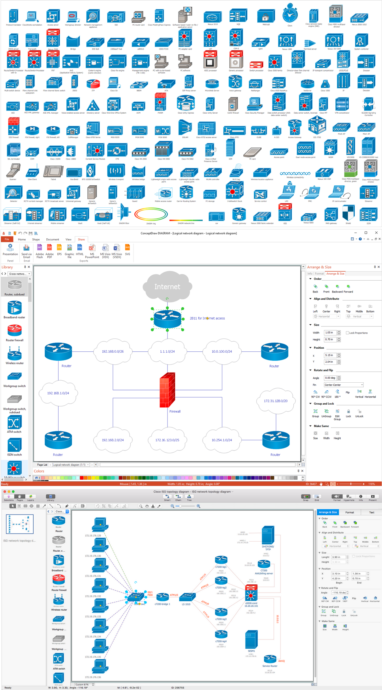 Picture: Network Diagramming Software for Design. Cisco Network DiagramsRelated Solution:Of course it is possible to keep network records in text documents, but it is very difficult to use them later. A more sound way to keep such documentation is to create a network diagram that might represent either logical network structure or physical. These diagrams are easy to understand and you will thank yourself later. There is a physical network diagram. It is a tool to represent, maintain and analysis of network equipment and interconnections. Network diagram depicts the actual network information in the attractive clear graphic form. One can learn here the LAN cable length, telecommunication type and carrying capacity. The diagram depicts servers, IP address and domain name as well. Also it shows location of hubs, switches, modems, routers, and other network equipment. The sets of special symbols and images delivered with ConceptDraw Network Diagrams solution are used to show network components. Symbols have a standard view. Therefore, various specialists can read the network diagram without any discrepancies.
 Picture: Network diagrams with ConceptDraw DIAGRAMRelated Solution:The VMware vNetwork Distributed Switch (vDS) is the new virtual switch (vSwitch) with vSphere 4 that extends the set of features of the VMware vNetwork Standard Switch (vSS). The VMware vSS is the base-level virtual networking alternative that extends the capabilities, configuration and appearance of the standard vSwitch in VMware ESX 3.5 to ESX 4.0 and vSphere 4. This example was created in ConceptDraw DIAGRAM using the Computer and Networks Area of ConceptDraw Solution Park and shows the VMware vDS network diagram.
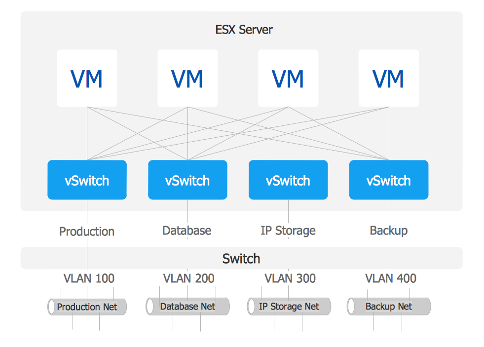 Picture: VMware vNetwork Distributied Switch (vDS). Computer and Network ExamplesRelated Solution:A Storage area network (SAN) is a dedicated network that provides access to data storage and operations only on the block level. SAN usually has own network of storage devices/elements and disk arrays that are connected with each other and to a remote data-sharing network. SANs are widely used for enhancing the storage devices (optical jukeboxes, disk arrays, tape libraries) that are accessible for networked servers. This example was created in ConceptDraw DIAGRAM using the Computer and Networks Area of ConceptDraw Solution Park. It shows the hybrid of Storage area network (SAN) and Network Attached Storage (NAS) technologies.
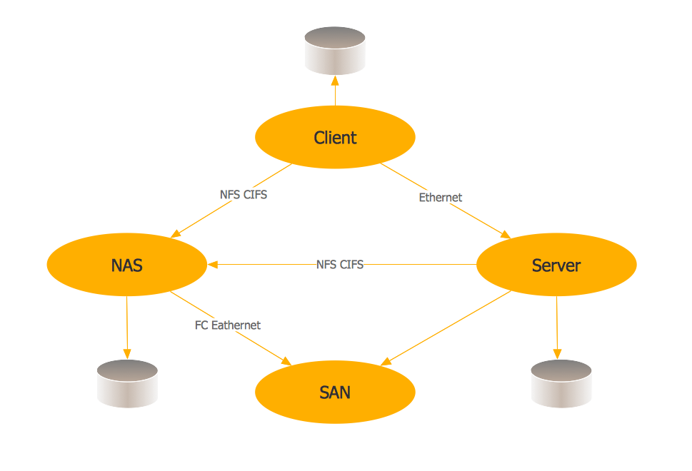 Picture: Storage area networks (SAN). Computer and Network ExamplesRelated Solution:ConceptDraw DIAGRAM is the best software for illustration the network topologies. It's very easy and quickly to design the network topology diagrams of any kinds and complexity in ConceptDraw DIAGRAM diagramming and vector drawing software using the Computer and Networks solution from Computer and Networks area of ConceptDraw Solution Park.
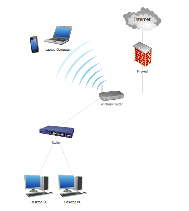 Picture: Network Topology IllustrationRelated Solution:Building plans are usually very complicated and a hard work to do. It would be nice to use a proper drawing software to facilitate the task. Design a site plan quick and easily with all the stencils and samples from ConceptDraw libraries. This drawing shows content of the ConceptDraw vector libraries related to the site planning and arrangement of the living environment. ConceptDraw delivers about 50 libraries containing near one and a half thousands vector objects that will help you to design territory arrangement plans and make the Site plan sketches. You can use the Parking and Roads library for designing a parking space, or drawing transport management schemes. The Site Accessories library provides a number of objects, that allow you to depict various equipment of vehicle access control, street lamps, benches, trash cans and other items of the street environment.
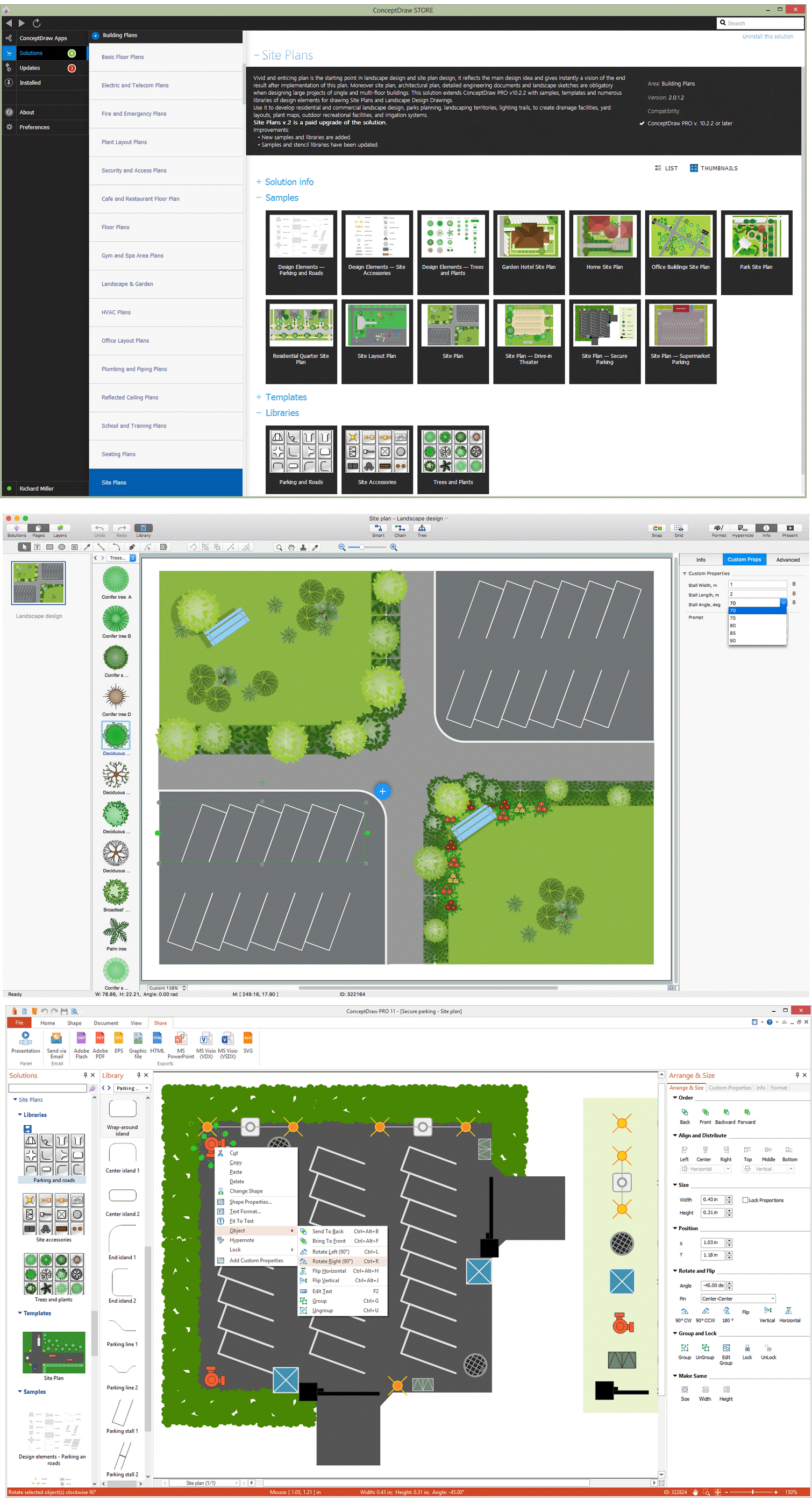 Picture: Building Drawing Software for Design Site PlanRelated Solution:Draw Network Topology and Computer Network Diagrams, Designs, Schematics, and Network Maps using ConceptDraw in no Time!
 Picture: Network Diagram SoftwareTopology NetworkWhen trying to figure out the nature of the problems occurring within a project, there are many ways to develop such understanding. One of the most common ways to document processes for further improvement is to draw a process flowchart, which depicts the activities of the process arranged in sequential order — this is business process management. ConceptDraw DIAGRAM is business process mapping software with impressive range of productivity features for business process management and classic project management. This business process management software is helpful for many purposes from different payment processes, or manufacturing processes to chemical processes. Business process mapping flowcharts helps clarify the actual workflow of different people engaged in the same process. This samples were made with ConceptDraw DIAGRAM — business process mapping software for flowcharting and used as classic visio alternative because its briefly named "visio for mac" and for windows, this sort of software named the business process management tools. This flowchart diagram shows a process flow of project management. The diagram that is presented here depicts the project life cycle that is basic for the most of project management methods. Breaking a project into phases allows to track it in the proper manner. Through separation on phases, the total workflow of a project is divided into some foreseeable components, thus making it easier to follow the project status. A project life cycle commonly includes: initiation, definition, design, development and implementation phases. Distinguished method to show parallel and interdependent processes, as well as project life cycle relationships. A flowchart diagram is often used as visual guide to project. For instance, it used by marketing project management software for visualizing stages of marketing activities or as project management workflow tools. Created with ConceptDraw DIAGRAM — business process mapping software which is flowcharting visio alternative or shortly its visio for mac, this sort of software platform often named the business process management tools.
 Picture: Process Flowchart: A Step-by-Step Comprehensive GuideRelated Solution:ConceptDrawDIAGRAM 18