Made with
ConceptDraw
DIAGRAM 18

Interior Design. Site Plan — Design Elements

Site plan — Design elements libraries

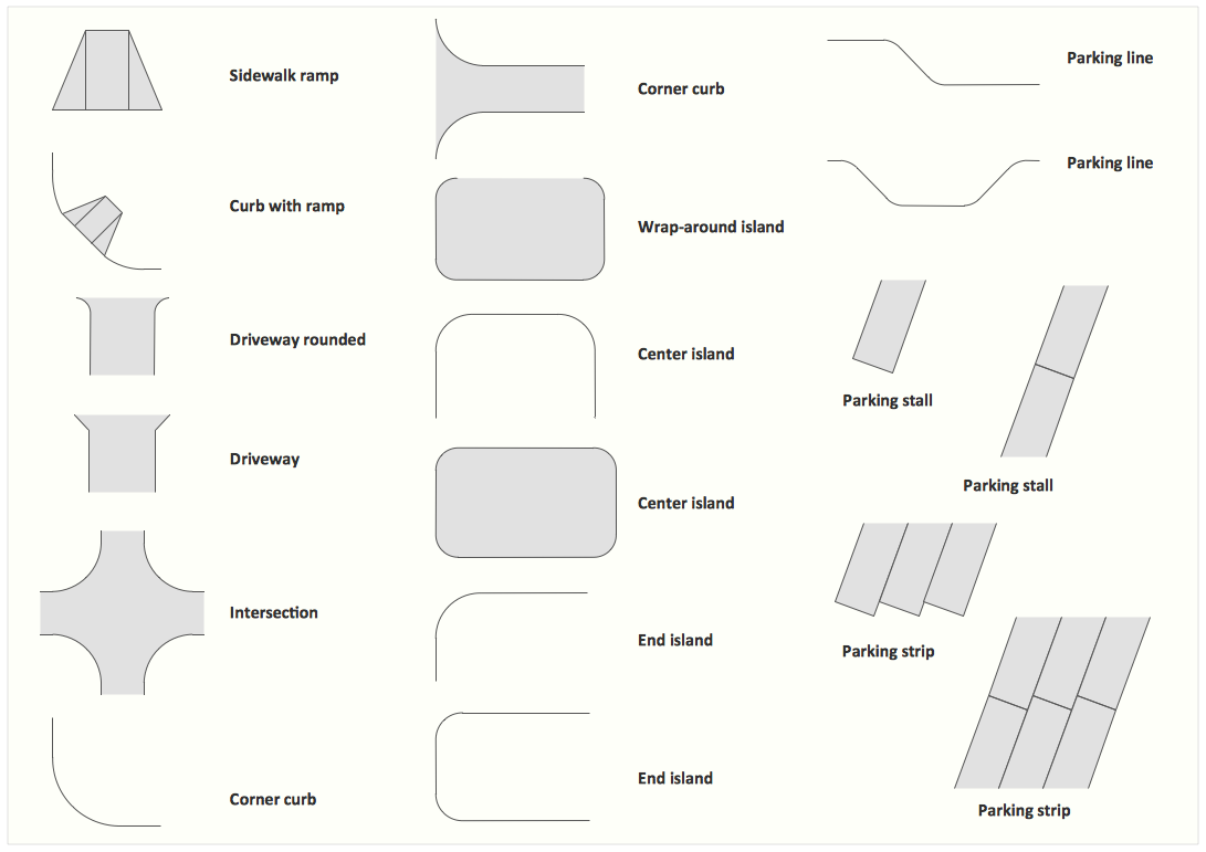
The vector stencils library Parking and roads contains shapes of parking lots and strips, parking spaces, driveways, street junctions, and interchanges for drawing site plans of parking facilities, on-street and off-street parking, and traffic management.

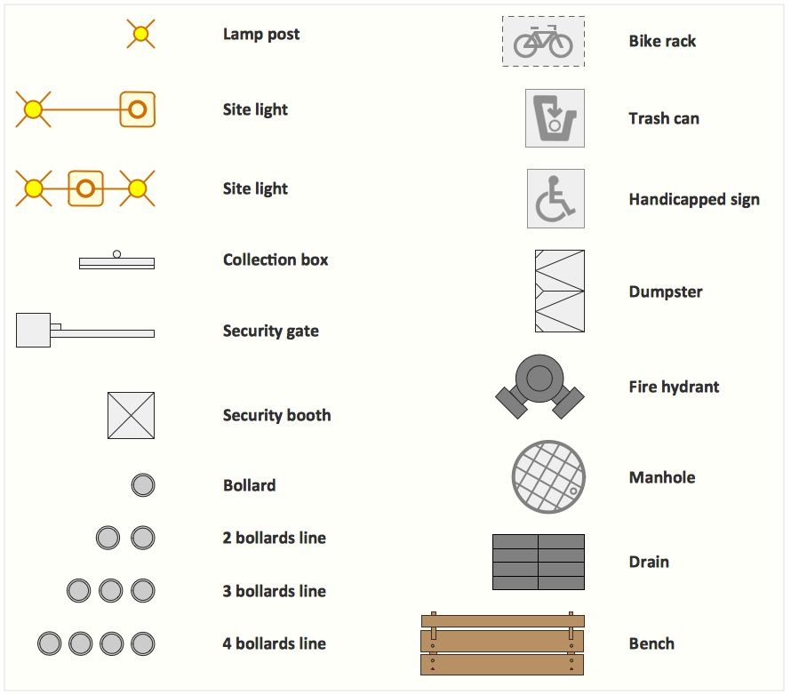
The library Site accessories contains shapes of vehicle access control equipment (tollbooth, tollgate, parking fees payment box), a handicapped sign, outdoor lighting, and garbage receptacles for drawing site plans of parking lots and site management.

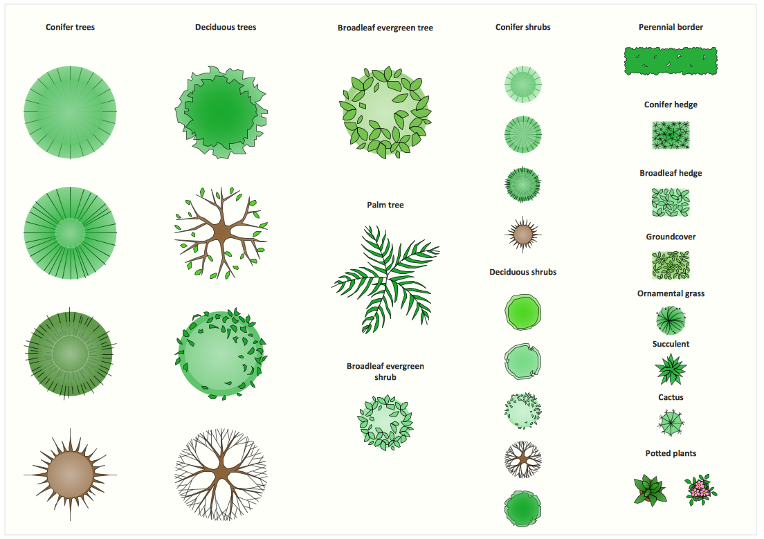
The library Trees and plants contains shapes of trees, hedges, groundcovers, greenery, and shrubbery for drawing site plans, landscape architecture, lawns, gardens, yards, parks planning, groundskeeping, landscape design, and arboretums.

Use these 3 libraries for ConceptDraw DIAGRAM diagramming and vector drawing software to draw site design plans and equipment layouts.

These design elements library are included in Site Plans solution from Building Plans area of ConceptDraw Solution Park.

The Parking and roads library contains 18 symbols:

  • Driveway rounded
  • Driveway
  • Wrap-around island
  • Sidewalk ramp
  • Curb with ramp
  • Intersection
  • Corner curb
  • End island
  • Center island
  • Parking line
  • Parking stall
  • Parking strip

The Trees and plants library contains 29 symbols:

  • Broadleaf evergreen tree
  • Potted plant
  • Cactus
  • Ornamental grass
  • Succulent
  • Perennial border
  • Groundcover
  • Conifer hedge
  • Broadleaf hedge
  • Broadleaf evergreen shrub
  • Deciduous shrub
  • Conifer shrub
  • Palm tree
  • Deciduous tree
  • Conifer tree

The Site accessories library contains 18 symbols:

Interior Design. Site Plan — Design Elements * Interior Design Software.  Design Elements — Trees and Plants Interior Design Software.  Design Elements — Site Accessories

Sample 1. Interior Design Software. Design Elements — Site Plan
for macintosh and windows

Solution Building Plans from ConceptDraw Solution Park provides vector stencils libraries with design elements for drawing Site Plans.

Use ConceptDraw DIAGRAM diagramming and vector drawing software enhanced with Building Plans solution to draw your own residential and commercial landscape design, parks planning, yard layouts, plat maps, outdoor recreational facilities, and irrigation systems.

Read more about Home and Landscape design

TEN RELATED HOW TO's:
There are many tools to manage a process or to illustrate an algorithm or a workflow. Flowcharting is one of those tools. However, it may be difficult to show complex processes that require multiple attributes or several people in a simple flowchart, so a cross-functional flowchart would be a solution for that situation. To create such flowchart, group processes and steps to labeled rows or columns, and divide those groups with horizontal or vertical parallel lines. It is worth mentioning that there are different types of cross-functional flowcharts, like opportunity or deployment flowchart. This diagram shows a cross-functional flowchart that was made for a trading process. It contains 14 processes, distributed through 5 lines depicting the participants who interact with the process. Also there are connectors that show the data flow of information between processes. The cross-functional flowchart displays a detailed model of the trading process, as well as all participants in the process and how they interact with each other. The lines in the flowchart indicates the position, department and role of the trading process participants.Cross-Functional Flowchart
Picture: Cross-Functional Flowchart
Related Solution:
In general, you can use any icons to represent network equipment on a diagram. However, there are some icons, for instance, Cisco icons, shapes, stencils and symbols, that are recognizable worldwide. Using those icons you can create Cisco network topology diagrams in minutes and share them anywhere. The icons depicting Cisco network equipment are recognized and generally applied as standard images for designing network diagrams. They are free to used , but can not be reworked. Cisco network diagrams are created to depict how signals processed on the network equipment and end-user computers and how data transfer through LAN or WLAN between nodes. The vector graphic library of ConceptDraw CISCO Network Diagrams solution includes about 90 icons of Cisco network equipment for designing computer network diagrams with ConceptDraw DIAGRAM.Cisco Network Topology. <br>Cisco icons, shapes, stencils and symbols *
Picture: Cisco Network Topology. Cisco icons, shapes, stencils and symbols
Related Solution:
UML Timing Diagram as special form of a sequence diagram are used to explore the behaviors of objects throughout a given period of time. ConceptDraw has 393 vector stencils in the 13 libraries that helps you to start using software for designing your own UML Diagrams. You can use the appropriate stencils of UML notation from UML Timing library.UML Timing Diagram, Design Elements *
Picture: UML Timing Diagram, Design Elements
Related Solution:
Electrical plan is a document that is developed during the first stage of the building design. This scheme is composed of conventional images or symbols of components that operate by means of electric energy. To simplify the creation of these schemes you can use house electrical plan software, which will not require a long additional training to understand how to use it. You only need to install the necessary software ant it’s libraries and you’ll have one less problem during the building projection. Any building contains a number of electrical systems, including switches, fixtures, outlets and other lightening equipment. All these should be depicted in a building electrical plans and included to general building documentation. This home electrical plan displays electrical and telecommunication devices placed to a home floor plan. On the plan, each electrical device is referenced with the proper symbol. Electrical symbols are used for universal recognition of the building plan by different persons who will be working on the construction. Not all possible electric symbols used on a certain plan, so the symbols used in the current home plan are included to a legend. The electrical home plan may be added as a separate document to a complete set of building plans.House Electrical Plan Software
Picture: How To use House Electrical Plan Software
Related Solution:
Working with personnel might be difficult if you are not prepared enough. To explain your workers all the details of communication with customers, you can draw an order process flowchart which will describe every step of the process and answer all the questions that might appear. You can view a lot of business process mapping diagram examples here, in ConceptDraw Solution Park. This business process flow chart is created to illustrate the sample work order process. Before an organization can make some work for a person, the customer work order request must be completed. It is needed for tracking and accountability objectives. We used this business process flowchart to show a certain tasks and actions assumed by an organization. This flowchart depicts the outside inputs that are needed to launch a process, and ways the organization delivers its outputs. This business process flowchart was created with a help of ConceptDraw Business Process Mapping solution.Work Order Process Flowchart. <br>Business Process Mapping Examples *
Picture: Work Order Process Flowchart. Business Process Mapping Examples
Related Solution:
Visio for Mac and Windows - ConceptDraw as an alternative to MS Visio. ConceptDraw DIAGRAM delivers full-functioned alternative to MS Visio. ConceptDraw DIAGRAM supports import of Visio files. ConceptDraw DIAGRAM supports flowcharting, swimlane, orgchart, project chart, mind map, decision tree, cause and effect, charts and graphs, and many other diagram types.Is ConceptDraw DIAGRAM an Alternative to Microsoft Visio? *
Picture: Is ConceptDraw DIAGRAM an Alternative to Microsoft Visio?
The behavior of worker in organization is influences organizational effectiveness. A simple block diagram made with ConceptDraw Block diagrams solution can improve the understanding of expectations of workers regarding what they l contribute to organization and what they wait to obtain. Making block diagram depicting the individual behavior in organization is used in HR management to obtain an optimal and positive overall contribution to the organization. The behavior of worker in organization is influences organizational effectiveness. A simple block diagram made with ConceptDraw Block diagrams solution can improve the understanding of expectations of workers regarding what they l contribute to organization and what they wait to obtain. Making block diagram depicting the individual behavior in organization is used in HR management to obtain an optimal and positive overall contribution to the organization.Basic Diagramming *
Picture: Basic Diagramming
Related Solution:
Root Cause Analysis Tree Diagram. Use the Root Cause Diagram to perform visual root cause analysis. Root Cause Analysis Tree Diagram is constructed separately for each highly prioritized factor. The goal of this is to find the root causes for the factor and list possible corrective action. ConceptDraw Office suite is a software for problem analysis.PROBLEM ANALYSIS. Root Cause Analysis Tree Diagram *
Picture: PROBLEM ANALYSIS. Root Cause Analysis Tree Diagram
Perfect charts and graphics diagramming software with rich examples and template. ConceptDraw is ideal to draw Charts and Graphics.Basic Diagramming *
Picture: Basic Diagramming
Related Solution:
Some organization hold offices for years and decades, or even build their own campuses. However, if it’s time for your organization to move to another building, drawing software for designing office layout plan would come in handy. With such software you can save a lot of time and create a new layout or try to save old layout in a new building. This office layout plan is an example of a typical office furniture and equipment arrangement. This drawing provides a graphic view of the office area and its facilities including furniture and office equipment. It can be used as template which represent, desks, files, and other pieces of equipment that can be re-arranged according the certain requirements to office space and facilities. The vector graphic objects that represent various office layout elements such as special office furniture and equipment can help you to shape a number of creative ideas and develop your office layout plan.Building Drawing Software for Design Office Layout Plan
Picture: Building Drawing Software for Design Office Layout Plan
Related Solution:
ConceptDraw
DIAGRAM 18