Bus Network Topology
Bus Network Topology Diagram
There is one of the most commonly used computer network topologies – bus network topology. Bus networks are well known for their nodes being located in a shape of a bus. The way such networks look reminds of a bus as the nodes in it are connected to one common linear, which is called a bus.
In this diagram of a form of a bus everyone can clearly see both the linear, the nodes and them directly connected to that linear.
There is a host on a bus, which is called a “Station”. It can also be called as a “Workstation”. Every of the “stations” or “workstations” receive all of the network traffic which is generated by each of such stations and has equal transmission priority. The nodes in such topology transmit the data at the same time as they work simultaneously by using the so called media access control technology. The example of such media access control technology can be a carrier sense multiple access as well as a bus master.
There are many advantages of such bus network topology, as it is always very simple to connect a computer or peripheral to a linear bus and it always requires less cable length than a star topology, which results in lower costs of having such topology. Also bus network topology within networks are simpler to extend by joining cable with connector or repeater. Any of the existing bus network topologies work better for small networks which can be also a disadvantage in case yours is quite large. Other disadvantages are: large amount of packet collisions on one network which results in high amounts of packet loss and the possibility of the network to be shut down in case there is a break in the main cable or in case one of the T connectors breaks. But, again, the good thing is that in this topology data being transferred may be accessed by any workstation.
There are two types of the bus network topologies, one of which is a “Linear bus” one. This type of network topology is the one where all of the nodes of the entire network are connected to one common transmission with only two endpoints. In this type of bus topology all of the data transmitted between nodes is transmitted over this common transmission medium and it is able to be received by all nodes at the same time. Another type of bus network topology is called “Distributed bus”. This type of network topology is the one, where all of the network nodes are connected to one common transmission medium and where this transmission medium has more, than two endpoints, which are created by adding the branches to the main section of the transmission medium.
If you work in IT or you, for some reason, want to illustrate the way bus network topology looks like and you want to make this drawing look truly professional, then you might spend long hours trying to create it yourself. Although, there is another option. If you find the right software to be able to use it in order to create such great looking, smart, professional bus network topology diagram, then it can be much simpler to finish with your drawing and so quicker.
We always recommend to use only the best software possible which is ConceptDraw DIAGRAM This software is a very special one and only the reason it was developed by the IT specialists from CS Odessa with experience in drawing charts, flowcharts, diagrams and schemes makes it so special. This application allows ConceptDraw DIAGRAM users to choose any of the available solutions full of stencil libraries with proper design elements as well as pre-made examples and templates of so many graphs, charts, plans, schemes, flowcharts and diagrams created by the team of CS Odessa IT specialists.
Having all of the options to use, including different solutions where you can always find the necessary tools, such as the design elements to use for your own great looking drawings or the existing examples as well as templates and layouts of the previously made drawings which you can always use as drafts for your own drawings, is always very beneficial.
In case you decide to get one of the solutions after downloading ConceptDraw DIAGRAM you can always download them either from the ConceptDraw STORE which is another product of CS Odessa, or this site. Each of the solutions provide at least one library with the stencils that can be used for making so many different charts, plans, schemes, flowcharts and diagrams, including the star network topology ones.
Having them means having pretty much everything you need to make it happen – to make a smart looking bus network topology diagram from a scratch using Computer and Networks solution from Computer and Networks area of ConceptDraw Solution Park which provides examples, templates and vector stencils library with symbols of local area network (LAN) and wireless LAN (WLAN) equipment.
You can always use it to draw the physical and logical network topology diagrams for wired and wireless computer communication networks, including the “Linear bus” and the “Distributed bus”.
No matter which of the mentioned above types of the computer network topology diagrams you want to create, you can always do it within only a couple of hours or even minutes, depending on your general experience of using ConceptDraw DIAGRAM software. Download it today in case you still do not have this unique and very convenient application and use it for making your own diagrams, great looking plans, schemes, charts and flowcharts.
Once you try and succeed in creating something special and professionally looking, then we doubt that you will stop using this unique software, but will recommend to those who do not have it yet and so somebody else will have a change to get this application and so simplify their work with drawing the schemes, charts, plans, diagrams and flowcharts.

Pic. 1. Bus Network Topology
Use it to draw the physical and logical network topology diagrams for wired and wireless computer communication networks.

Pic. 2. Bus Network Topology Diagram
Download ConceptDraw DIAGRAM already today to have a chance to create your first great looking drawing. Do not forget to get also ConceptDraw STORE so you have all of the tools developed and provided by CS Odessa team of IT specialists.
See Also Network Topologies:
TEN RELATED HOW TO's:
The ConceptDraw Flowchart component includes a set of samples and templates. This geathered as flowchart maker toolbox which focused on drawing flowcharts of any industry standards.
Picture: Flowchart Components
Related Solution:
This sample was created in ConceptDraw DIAGRAM diagramming and vector drawing software using the Computer and Networks solution from Computer and Networks area of ConceptDraw Solution Park.
This is example of the Toroidal network topology
Network topology is the topological structure of the computer network.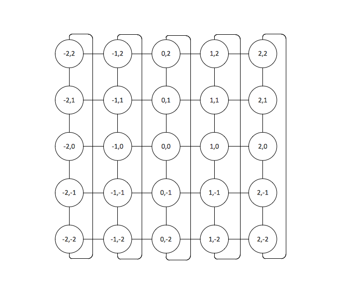
Picture: Toroidal Network Topology
Related Solution:
UML Use Case Diagrams are used to illustrate the structure of arbitrarily complex systems and illustrates the service consumer - service provider relationship between components.
Picture: UML Use Case Diagram. Design Elements
It’s not easy to plan all the details of your landscape at once. Therefore, you can use a bubble diagram to create a draft of the future project. You can develop any bubble diagrams and use them in your landscape design project with ConceptDraw DIAGRAM and it’s predesigned templates.
This bubble diagram can be applied while initiating the development of garden and landscape design. The bubble diagrams used for this purpose are different from the classic bubble diagrams. Being used in landscape and garden design, they obtain the quite another understanding. Bubbles in this diagram visualize some captured areas, which define the general spaces of a future garden: lawn, flower garden, pool, built-up area, lighting, etc. The bubble diagram represents the landscape project without any special expenses on its creation. It is better to make such simple sketch before you drill down into detailed project and cost estimates.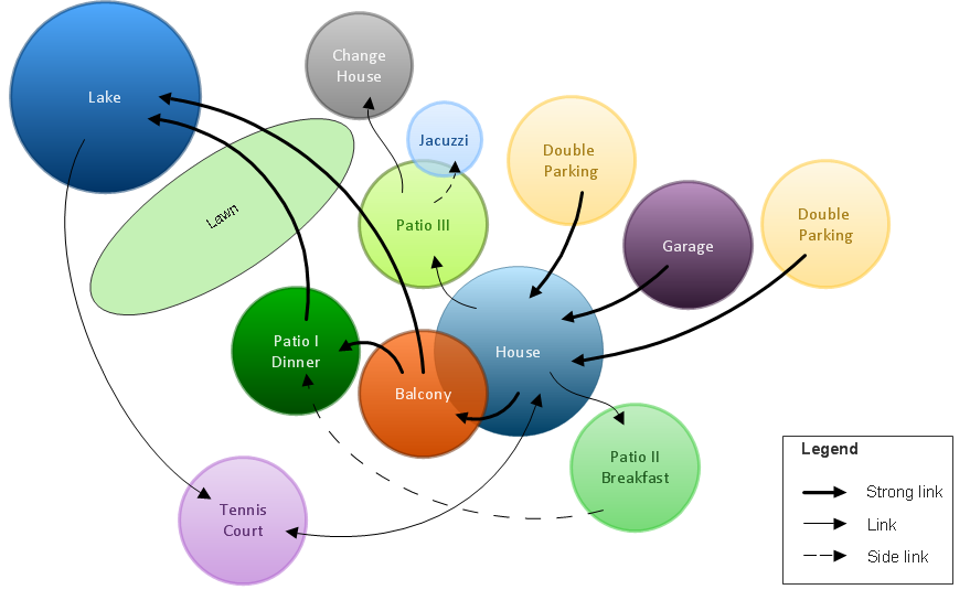
Picture: Bubble diagrams in Landscape Design with ConceptDraw DIAGRAM
ConceptDraw - Organigram software allows quickly create Organigrams and much more. ConceptDraw DIAGRAM is an ideal tool for Administrative staff to clearly demonstrate the company orgchart professional.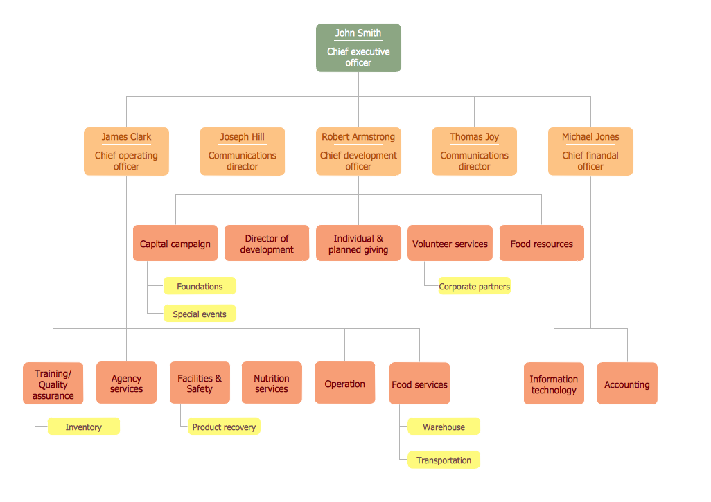
Picture: Organigrams with ConceptDraw DIAGRAM
Related Solution:
If you are an advanced diagramming software user, you might use it daily. Traversing the Internet in searching of alternative to MS Visio for MAC and PC, you can fulfill all your requirements with ConceptDraw DIAGRAM. Don’t hesitate to transfer your documents to another operating system.
When looking for a smart and simple tool for business diagrams as alternative to MS Visio for Apple OS X platform, ConceptDraw DIAGRAM certainly is the best choice. Making many kinds of business charts, numerous technical drawings is what ConcepDraw DIAGRAM is the best. One can easy create any diagram and complete it perfectly and quickly. The big collection of vector object libraries, templates and samples, make it the best Microsoft Visio alternative: ConceptDraw DIAGRAM is simpler to use, less expensive, and supports project management and mind mapping methods.
Picture:
In Searching of Alternative to MS Visio for Mac and PC
with ConceptDraw DIAGRAM
When describing any computer network, we imagine a set of devices and nodes, arranged in some way. Talking about network structures, we should distinguish physical and logical network topologies, as physical topology is about devices location and logical topology illustrates data flow. In the same time, they do not have to match, and some devices, such as repeaters, may have a physical star layout, but a bus logical topology.
There are two main types of computer network topologies: Physical topology that show the physical organization of a network - equipment and types of connections. Star network topology involves a set of devices that is connected to a single hub (router). Ring network topology means that, devices connected according this topology have two connections, connecting with nearby devices to make a loop. Bus network topology is the topology presented at the current diagram. It is similar to a ring topology. The difference is that data moves up and down a linear connection, copying itself where network equipment works as bus-stations along the way. This network topology can be used for small network, or when adding an extra device into a network.
Picture: Network Topologies
Related Solution:
The Internet is a huge world with unlimited possibilities. But with all its numerous advantages, the Internet also conceals many dangers and security threats, that's why we advise you to follow simple network security tips. ConceptDraw DIAGRAM diagramming and vector drawing software supplied with Network Security Diagrams Solution from the Computer and Networks Area of ConceptDraw Solution Park is an ideal software for easy designing Network Security Diagrams and attractive illustrations with effective network security tips.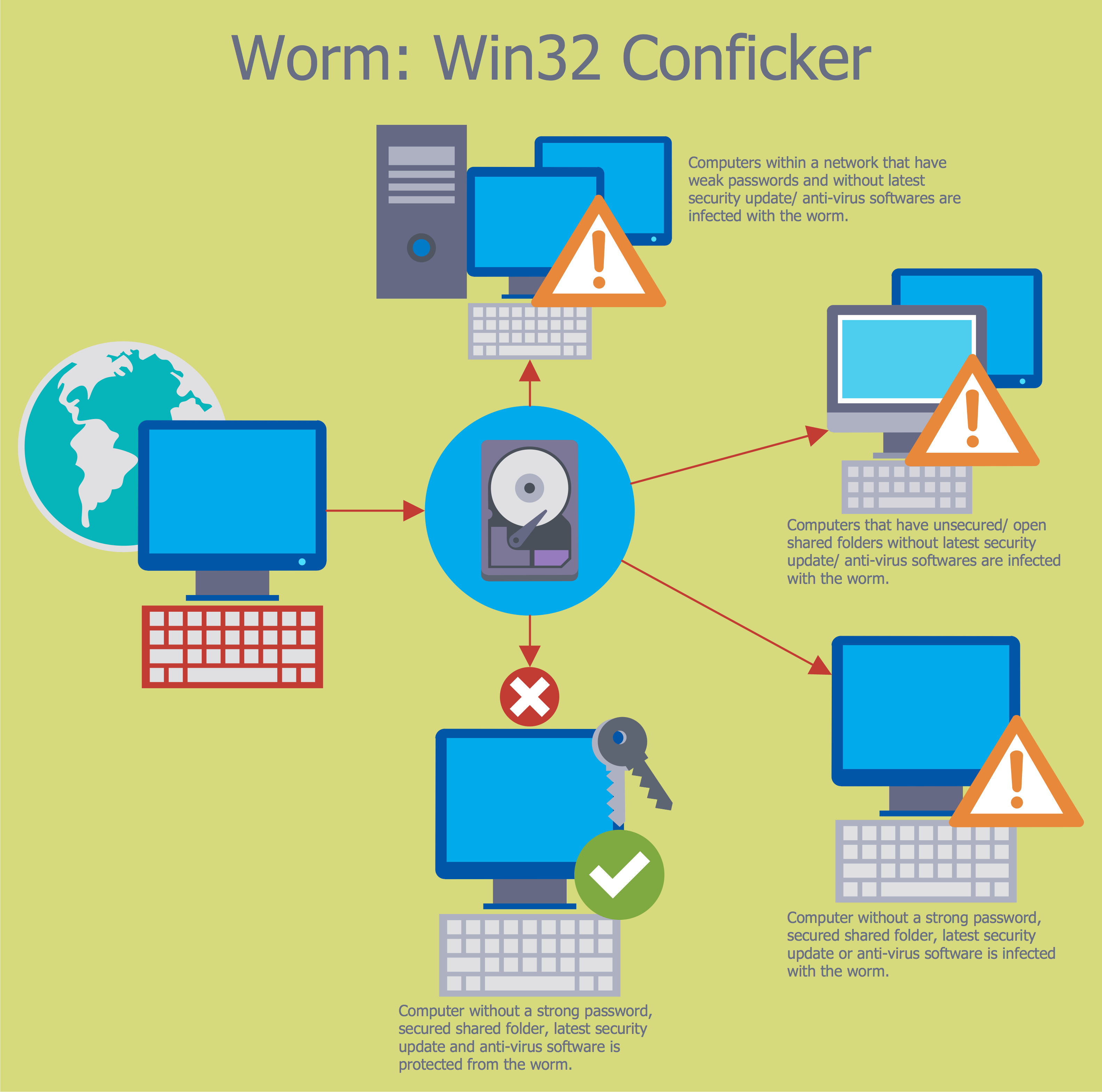
Picture: Network Security Tips
Related Solution:
Unfortunately, a man can’t predict the future and no one is safe from natural disasters, such as floods, earthquakes, hurricanes or fires. Nonetheless, what you can do to ensure safety for you and your relatives is to create an emergency plan, so everyone will know what to do if emergency happens. Keep that plan simple and train it several times a year so that no one could forget any details of it.
Fire and emergency plans are important to supply people with a visual safety solution. This diagram presents a set of standard symbols used to depict fire safety, emergency, and associated information. Using clear and standard symbols on fire emergency plans provides the coherence of collective actions , helps to avoid embarrassment, and improves communications in an emergent situation. The fire emergency symbols are intended for the general emergency and fire service, as well as for building plans ,engineering drawings and insurance diagrams. They can be used during fire extinguishing and evacuation operations, as well as trainings. It includes vector symbols for emergency management mapping, emergency evacuation diagrams and plans.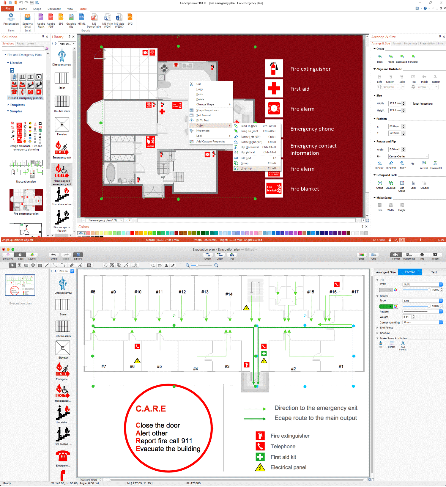
Picture: Emergency Plan
Related Solution:
Electrical Engineering Solution used together with ConceptDraw DIAGRAM drawing facilities makes short a work of drawing various electrical and electronic circuit schemes. A library of vector objects composed from symbols of Analog and Digital Logic elements of electric circuit includes 40 symbolic images of logic gates, bistable switches of bi-stable electric current, circuit controllers, amplifiers, regulators, generators, etc. All of them can be applied in electronic circuit schemes for showing both analog and digital elements of the circuit.
Electrical Engineering Solution used together with ConceptDraw DIAGRAM drawing facilities makes short a work of drawing various electrical and electronic circuit schemes. A library of vector objects composed from symbols of Analog and Digital Logic elements of electric circuit includes 40 symbolic images of logic gates, bistable switches of bi-stable electric current, circuit controllers, amplifiers, regulators, generators, etc. All of them can be applied in electronic circuit schemes for showing both analog and digital elements of the circuit.
Picture:
Electrical Diagram Symbols F.A.Q.
How to Use Electrical ConceptDraw Diagram Software
Related Solution:
