Made with
ConceptDraw
DIAGRAM 18

Network Topologies

Small and medium-sized companies have network infrastructure which can total ten or more networking and computing devices (computers, servers, printers, telephones, routers, fax machines, scanners, etc.) All elements of a network have their own settings configured for fast and reliable service. As a company grows, it is necessary to incorporate new devices into the network, update existing devices, change the network topology, and even add new subnets. Changing the configuration of the network is only possible if there is documentation of the operating infrastructure.

To achieve high-quality documentation of network infrastructure, it is necessary to include the overall network structure topology, a communication scheme, the layout of the main devices, the scheme arrangement of servers in server racks, the list of installed services, services and databases for each server, and the scheme of corporate PBX.


Network Topology Diagram Software

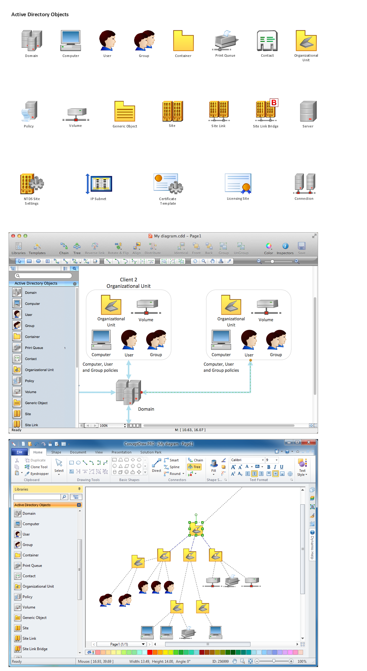
ConceptDraw DIAGRAM is a powerful Network Topology Diagram software and intelligent vector graphics engine that can be used for network topologies diagrams. The shape libraries contain ready-to use icons of computers, servers, network devices, standard symbols and smart connectors for the quick and easy arrangement of network diagrams.

Network Topology icons, shapes and symbols

With ConceptDraw DIAGRAM you can simply create professional looking diagrams:

  • Network topology,
  • Physical network,
  • Logical network,
  • Network mapping,
  • Home area networks (HAN),
  • Wireless network,
  • Cisco network topologies,
  • Fully connected network topology,
  • Bus network topology,
  • Star network topology,
  • Ring network topology,
  • Mesh network topology,
  • Tree network topology,
  • Cable network,
  • Network wiring,
  • Local area network (LAN),
  • Wide area network (WAN) topology,
  • Metropolitan area networks (MAN),
  • Campus area networks (CAN),
  • Storage area networks (SAN),
  • Near-me area networks (NAN),
  • Personal area (PAN) networks,
  • Near field communication (NFC),
  • ISG network,
  • Interactive voice response (IVR) networks,
  • Activity network,
  • Local network area,
  • Network security,
  • Network wiring cable,
  • Computer network architecture,
  • Enterprise private network,
  • Internet networks,
  • Network configuration,
  • Active directory network,
  • Network protocols,
  • Network voip,
  • Virtual networks,
  • Virtual private networks (VPN),
  • Rack diagrams,
  • Network layout,
  • Backbone network,
  • Radio networks,
  • Television networks,
  • Telecommunication networks,
  • Overlay networks,
  • 3D network diagrams
  • ATM-Network,
  • Butterfly network,
  • EIGRP,
  • IGMP,
  • MPLS,
  • OSPF Network,
  • P2MP network,
  • DES network,
  • Software Defined Networking System Overview,
  • Cloud Computing,
  • Mesh network,
  • Internet Connectivity,
  • Computer network,
  • Digital Communications Network,
  • Netflow architecture,
  • Network Community Structure,
  • phone networks,
  • Overlay network,
  • Office Network,
  • VMware vNetwork Distributied Switch (vDS),
  • EPN Frame-Relay and Dial-up Network,


What is Network Topology

Network topology is the topological structure of the computer network. Network topology can be physical or logical. The logical topology describes the network dataflows from one device to the next. The physical topology is the arrangement of the different elements of the computer network such as computers, cables and other devices. The physical topology shows the cabling layout of the network, the locations of the nodes and interconnections between cables and nodes. A network logical and physical topologies can be the same.

There are the following basic types of the network topologies:


Bus Network Topology

In local area networks where bus topology is used, each node is connected to a single cable. A signal from the source travels in both directions to all machines connected on the bus cable until it finds the intended recipient. If the data matches the machine address, the data is accepted, otherwise the machine ignores the data. Since the bus topology consists of only one wire, it is rather inexpensive to implement when compared to other topologies. However, the low cost of implementing the technology is offset by the high cost of managing the network. Additionally, since only one cable is utilized, it can be the single point of failure. If the network cable is terminated on both ends and when without termination data transfer stop and when cable breaks, the entire network will be down.

Bus Network Topology

Pic. 1. Bus Network Topology


Star Network Topology

In local area networks with a star topology, each network host is connected to a central hub with a point-to-point connection. In Star topology every node (computer workstation or any other peripheral) is connected to central node called hub or switch. The switch is the server and the peripherals are the clients. The network does not necessarily have to resemble a star to be classified as a star network, but all of the nodes on the network must be connected to one central device. All traffic that traverses the network passes through the central hub. The hub acts as a signal repeater. The star topology is considered the easiest topology to design and implement. An advantage of the star topology is the simplicity of adding additional nodes. The primary disadvantage of the star topology is that the hub represents a single point of failure.

Star Network Topology

Pic. 2. Star Network Topology


Ring Network Topology

A network topology that is set up in a circular fashion in which data travels around the ring in one direction and each device on the ring acts as a repeater to keep the signal strong as it travels. Each device incorporates a receiver for the incoming signal and a transmitter to send the data on to the next device in the ring. The network is dependent on the ability of the signal to travel around the ring. When a device sends data, it must travel through each device on the ring until it reaches its destination. Every node is a critical link.

Ring Network Topology

Pic. 3. Ring Network Topology


Mesh Network Topology

A mesh network is a network topology in which each node relays data for the network. All nodes cooperate in the distribution of data in the network. A mesh network can be designed using a flooding or a routing techniques. When using a routing technique, the message is propagated along a path, by hopping from node to node until the destination is reached. To ensure all its paths' availability, a routing network must allow for continuous connections and reconfiguration around broken or blocked paths, using self-healing algorithms. The self-healing capability enables a routing based network to operate when one node breaks down or a connection goes bad. As a result, the network is typically quite reliable. A mesh network whose nodes are all connected to each other is a fully connected network. Mesh networks can be also seen as one type of ad hoc network.

Mesh Network Topology

Pic. 4. Mesh Network Topology


Tree Network Topology

This particular type of network topology is based on a hierarchy of nodes. The highest level of any tree network consists of a single 'root' node that is connected with a single or multiple nodes in the level below by point-to-point links. These lower level nodes are also connected to a single or multiple nodes in the next level down. Tree networks are not constrained to any number of levels, but as tree networks are a variant of the bus network topology, they are prone to crippling network failures should a connection in a higher level of nodes fail/suffer damage. Each node in the network has a fixed number of nodes connected to it at the next lower level in the hierarchy, this number referred to as the 'branching factor' of the tree.

Tree Network Topology

Pic. 5. Tree Network Topology


Fully Connected Network Topology

A fully connected network, complete topology, or full mesh topology is a network topology in which there is a direct link between all pairs of nodes. In a fully connected network with n nodes, there are n(n-1)/2 direct links. Networks designed with this topology are usually very expensive to set up, but provide a high degree of reliability due to the multiple paths for data that are provided by the large number of redundant links between nodes. This topology is mostly seen in military applications.

Fully Connected Network Topology

Pic. 6. Fully Connected Network Topology


Network Topologies

Pic. 7. Common Network Topologies Diagram

These samples was created in ConceptDraw DIAGRAM diagramming and vector drawing software using the Computer Network Diagrams Solution from Computer and Networks area of ConceptDraw Solution Park. These diagrams show the basic types of the network topologies.

Network Topology solution

Pic. 8. Network Topologies Solution

Use the predesigned vector stencils, examples and templates from the Computer Network Diagrams Solution for ConceptDraw DIAGRAM to design your own professional Computer Network Topology Diagrams quick and easy.

TEN RELATED HOW TO's:
A Venn diagram, sometimes referred to as a set diagram, is a diagramming style used to show all the possible logical relations between a finite amount of sets. Having ConceptDraw DIAGRAM software one allows anyone who cares for their drawings to look not only nice but also smart and professional.Venn Diagram Examples for Problem Solving. Chomsky Hierarchy
Picture:
Venn Diagram Examples for Problem Solving
Computer Science. Chomsky Hierarchy
Related Solution:
All networks are different and require a different wiring. They can be simple and consist of two computers connected with a network cable, or complex and consist of several computers, switches, hubs. This example was created in ConceptDraw DIAGRAM using the Computer and Networks solution from the Computer and Networks area of ConceptDraw Solution Park and shows the Network wiring.Network wiring. <br>Computer and Network Examples *
Picture: Network wiring. Computer and Network Examples
Related Solution:
It's obvious that any building has a plan, and it is a hard and diligent work to draw one. And it's great that nowadays there are software tools for those purposes. For instance, ConceptDraw Pro contains design elements depicting different parts of sport fields. It's easy to use them and it facilitates your work exponentially. Planning of athletic facilities, playgrounds and Leisure Centers, needs thoughtful and creative approach. Any layout regarding to sport facilities should satisfy the requirements of both athletes and spectators. Well designed sport fields , playgrounds and recreation spaces attract people to sport activities in the cities and countryside. ConceptDraw Sport Field Plans solution is useful and convenient professional drawing tool. It delivers the kit of vector libraries that can be used for representing sport fields, sportgrounds and recreation spaces: football, hockey, volleyball, cricket, basketball , swimming pool, etc.Building Drawing Software for Design Sport Fields
Picture: Building Drawing Software for Design Sport Fields
Related Solution:
Draw Network Topology and Computer Network Diagrams, Designs, Schematics, and Network Maps using ConceptDraw in no Time!Network Diagram Software<br>Topology Network *
Picture: Network Diagram SoftwareTopology Network
The Audio & Video Connectors solution contains a set of pre-designed objects, libraries, templates, and samples; allowing quick and easy diagramming of various configurations of audio and video devices.Audio and Video Interfaces and Connectors *
Picture: Audio and Video Interfaces and Connectors
Related Solution:
ConceptDraw DIAGRAM is a powerful Network Engineering software thanks to the Vehicular Networking Solution and many other networking solutions from the Computer and Networks Area of ConceptDraw Solution Park.Network Engineering *
Picture: Network Engineering
Related Solution:
Intelligent Services Gateway (ISG) is a feature set that is available on the Cisco Routers. ISG provides the session management, the structured framework, the policies for management the various access networks, provides the information about the session bandwidth and network accessibility. This example was created in ConceptDraw DIAGRAM using the Computer and Networks solution from the Computer and Networks area of ConceptDraw Solution Park and shows the Intelligent Services Gateway (ISG) network.Intelligent Services Gateway (ISG) network. <br>Computer and Network Examples *
Picture: Intelligent Services Gateway (ISG) network. Computer and Network Examples
Related Solution:
Action Plan - For the action planning define people and groups involvement in corrective actions by roles, identify logical sequences of scheduled actions and critical path of problem solving, identify possible risks of action plan and propose preventive actions. ConceptDraw Office suite is a software for decision making and action plan.The Action Plan *
Picture: The Action Plan
If you ever tried programming, you could face a lot of problems as a beginner. To help yourself, create a flowchart to follow an algorithm logic. Flowchart represents a program as a sequence of steps depicted in special symbols for each type of action. This image of the interactive diagram made in ConceptDraw DIAGRAM applying the Live Objects technology. The diagram shows the effect of Selection Sort algorithm. The left part of the chart is the input area. The diagram in the central part of the drawing is a flow chart showing of the selection sort algorithm. The flowchart includes basic flowchart symbols, that represent various stages of algorithm. The flowchart symbols are connected with arrows ended lines, that depict the direction of the process flow. On the right side — the result is displayed.Business process flowchart showing structured operational workflow
Picture: What Is a Flowchart? Definition, Symbols, Examples and How to Create One
Related Solution:
House of Quality Matrix Software - Use the predesigned objects from the Involvement Matrix Objects Library from the Seven Management and Planning Tools Solution to create professional looking House of Quality Matrices in minutes.House of Quality Matrix Software *
Picture: House of Quality Matrix Software
Related Solution:
ConceptDraw
DIAGRAM 18