DFD Library — Design elements
Data Flow Diagram (DFD) notationsData flow diagram is known to be a graphical representation of some data flow through a particular information system in a way of modelling its process aspects. It is known to be often used as one of the steps for creating an overview of the needed system as well as for visualizing some data processing in the structured design. Any data flow diagram can show the way the information can be output from and input to some system, as well as to show in what way it can advance through the mentioned system. It is very important to mention the place this data is being stored, instead of showing the timing of some process. Data flow diagram, or simply DFD, can be also called as “Flow Chart”. The terms are very similar as they both can be used for illustrating and so representing a flow of the needed data and all created in ConceptDraw DIAGRAM diagramming and drawing software. Flow diagrams can be Data Flows ones, Entity Relationship ones, Unified Modelling Language ones, and other, but the first one — data flow diagram, or DFD – is mostl commonly used for representing any needed data flow in some information system in a graphical way. With help of DFD you can always represent any needed system overview in outline in ConceptDraw DIAGRAM application and having the needed solution, such as a Data Flow Diagrams one, which can be found in ConceptDraw STORE application, can simplify your work of making these drawings so it can take only a few minutes to get the professionally looking as well as smart looking result. Any data flow diagram can be also used for providing the end user with all the needed information about the inputting data. It can also be useful for mentioning the information about some particular system, which can be developed both at the stages of design and analysis. There are a few notations, which you can always use for creating the needed data flow diagrams: “Yourdon and Coad” and “Gane and Sarson” one, used for defining numerous visual representations of the data flows, as well as external entities, data stores and other processes within some system. There are the so-called “Logical Data Flow Diagrams”, which you can also create with the help of ConceptDraw DIAGRAM diagramming and drawing software. It is always very useful to capture the needed data flows, as they are known to be necessary for the system to operate. Thus, in order to describe all the needed processes and the needed data, any DFD, whether it is a logical one or a physical one, can be helpful and useful to make. Another mentioning type of DFD is “Physical Data Flow Diagram”. It is also well known to be called as the “Current Physical Data flow diagram”, used for the purpose of showing the way in what some system is implemented. You can make any needed, having such vector stencils, as representations of the terms of “State”, “Start State”, “External Interactor”, “Oval Process”, “Object”, “Entity (Rounded Corners)”, “Entity Relationship”, “Stop State”, “Entity with ID and Location Mentioned (Rounded Corners)”, “Data Store”, “Entity”, etc. Within the “Gane-Sarson Notation” such terms as “External Entity”, “Process”, “Process (with location)”, “Top to Top Side connector”, “Data Store”, “Jump”, “Angled Corners”, “Side to Side connector”, “Top to bottom Variable connector”, “Bottom to Side connector”, “Side to Same Side connector”, etc. can be used. The mentioned “Process” is known to be either a manipulation or work used for transforming some data, for performing some necessary computations, for making the needed decisions or for directing the data flows, which are known to be based on the definite business rules. Such processes can be illustrated with the aid of the circles or some rectangle (usually segmented) within some data flow diagram, including some process’s name as well as process’s number. Any data flow is known to be a movement of some data between the following three constituents: the entity, the data store and the process. Such data flow is known to be portraying the interface between different components within the data flow diagram. Any flow of data within some data flow diagram is known to be named in order to reflect the nature of the data itself which is being used. Any data flow, which is represented with the help of an arrow, is known to be annotated with the data name. Process The process is the manipulation or work that transforms data, performing computations, making decisions, or directing data flows based on business rules. Processes can be drawn as circles or a segmented rectangle on a DFD, and include a process name and process number.
Pic. 1. DFD, Process Data Stores A data store is where a process stores data between processes for later retrieval by that same process or another one. Data stores are usually drawn as a rectangle with the righthand side missing and labeled by the name of the data storage area it represents, though different notations do exist.
Pic. 2. DFD, Data Store Data Flow Data flow is the movement of data between the entity, the process, and the data store. Data flow portrays the interface between the components of the DFD. The flow of data in a DFD is named to reflect the nature of the data used. Data flow is represented by an arrow, where the arrow is annotated with the data name.
Pic. 3. DFD, Data Flow External Entities An entity is the source or destination of data. The source in a DFD represents these entities that are outside the context of the system. Entities are often represented as rectangles. Entities are also referred to as agents, terminators, or source/sink.
Pic. 4. DFD, External Entities The Data Flow Diagrams solution from the Software Development area of ConceptDraw Solution Park provides three vector stencils libraries for drawing DFD using the ConceptDraw DIAGRAM diagramming and vector drawing software. The design elements library "Data flow diagram (DFD)" contains 15 symbols for drawing both context-level data flow diagram and Level 1 DFD.
Pic. 5. Data Flow Diagram (DFD) Symbols The design elements library "DFD, Gane-Sarson notation" contains 12 symbols of Gane-Sarson DFD notation.
Pic. 6. DFD, Gane-Sarson notation symbols The design elements library "DFD, Yourdon and Coad notation" contains 22 symbols of Yourdon/DeMarco DFD notation.
Pic. 7. DFD, Yourdon and Coad notation symbols There are many other nuances about creating data flow diagrams, but once you have ConceptDraw DIAGRAM software as well as ConceptDraw STORE application downloaded from this site in order to use its Data Flow Diagrams solution, you can always make any needed DFD within only a few minutes using the pre-made examples and templates of such drawings. Among the mentioned layouts, you can find the following: “DFD – Model of Small Traditional Production Enterprise”, “DFD – Process of Account Receivable”, “Data Flow Diagram (DFD)”, “DFD — CERES”, “DFD — Coad/Yourdon Object Oriented Analysis Model”, “DFD — Last Resort Hotel Book Room Process”, “DFD — Interaction between IDMA and Preprocessor”, etc. The available stencil libraries from the mentioned solution allow all ConceptDraw DIAGRAM users to get such design elements which represent: “External Entity”, “Angled connectors”, “Process”, “Process (with Location)”, “Jump”, “Top to Bottom Variable connector”, “Side to Side connector”, “Bottom to Side connector”, “Top to Top Side connector” and “Side to Same Side connector” from the “Gane-Sarson notation” library; “Class and Object”, “State”, “Data Store”, “Generalization and specialization structure”, “Whole-part structure”, “Condition”, “Loop”, “External interaction”, “Data process”, “Multiple process”, “State”, “Multi-state”, “Stop state”, “Process (offset)”, “Process”, “Center to center flow”, “Class”, “Data store”, “Loop on center”, “Instance” and “Message” from the “Yourdon and Coad notation” library. Try the mentioned tools to create smart and professionally looking dfd for your own use. |


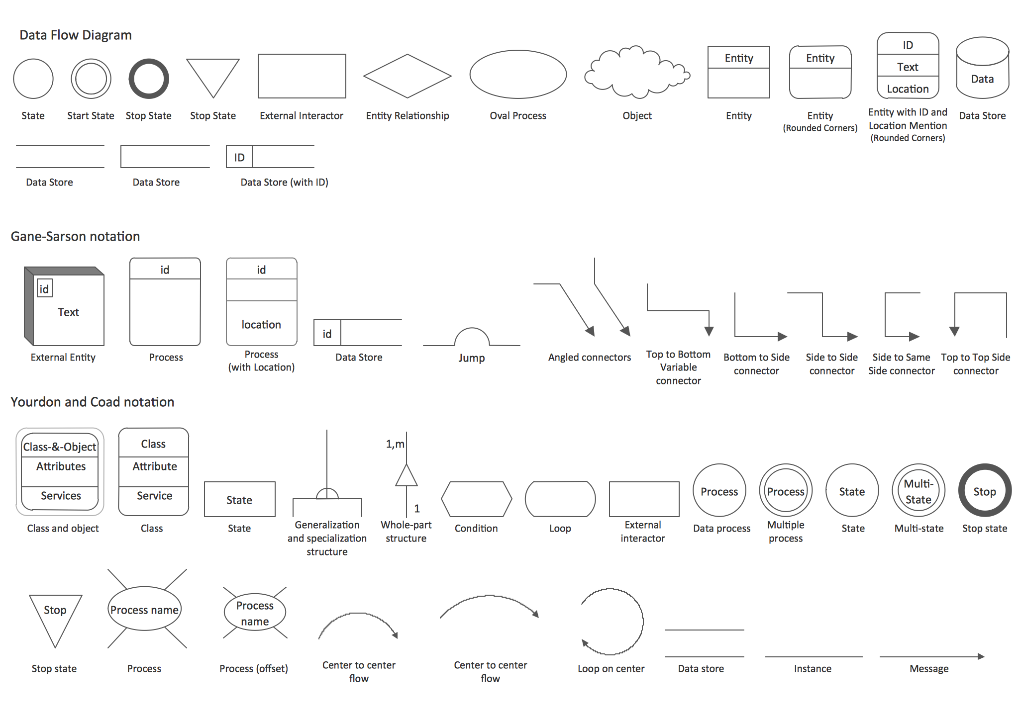
Pic. 8. DFD Library — Design elements
Data Flow Diagrams Sample: