CCTV Surveillance System Diagram. CCTV Network Diagram Example
The closed-circuit television, or shortly CCTV, can also be known simply as a video surveillance. It is the use of the video cameras for transmitting the signals to some particular place on a limited set of the monitors. The closed-circuit differs from the broadcast one because the signal is not that widely and openly transmitted, but it may employ point to multipoint (P2MP), mesh wired or wireless links, or point to point (P2P) way.
Although almost all video cameras fit the mentioned definition, the term can be applied to those who used the surveillance in the areas where monitoring may be needed: pubs, bars, casinos, schools, banks, hotels, universities, airports, hospitals, restaurants, clinics, military installations, convenience stores, shops, supermarkets and other areas as security is needed in most of the public places nowadays.
Sometimes Videotelephony can also be called as "CCTV". The surveillance of the public is common in lots of places all around the world. In such cases CCTV is very commonly used. In the recent years, the use of the body-worn video cameras has become a new form of surveillance. They are often used in the law enforcement, so you can see the cameras located on the police officers’ chests or on their heads. Any video surveillance has been discussed by debating as there needs to be a balance in its use with keeping the individuals' right to their own privacy, even when they are in public places.
In the industrial plants, the CCTV equipment can be used for observing different parts of one process from a central control room. The CCTV systems can always operate on a constant basis or only when required for monitoring the particular events. There is also a more advanced form of CCTV existing, which are digital video recorders that are known to be providing the recording for many years, having lots of quality as well as performance options and even some extra features, for instance, the motion detection and the email alerts.
The decentralized IP cameras equipped with the megapixel sensors are known to be supporting the recording directly to the network-attached storage devices. It can be also done in a way of the internal flash for the stand-alone operation. There are all together about 350 million surveillance cameras around the world nowadays, 65% of which are known to be installed in Asia. The CCTV growth has been slowed down a bit in the recent years though.
The earliest video surveillance systems involved non-stop monitoring as there was no other way to record as well as to store any recorded information. The development of the so-called “reel-to-reel media” enabled such recording of the surveillance footage. The mentioned systems required special magnetic tapes which had to be changed manually. It was not very convenient and it took lots of time, it was expensive and it was an unreliable process. During such process the operator had to manually thread the tape from the tape reel all the way through the recorder on the empty take-up reel.
Because of such inconveniences, the video surveillance could not become popular and widespread. The “VCR technology” became more popular in the 1970s as it became easier to record as well as to erase information, and so to use the video surveillance which became much more convenient and so common. During the 1990s, the digital multiplexing was developed, providing an opportunity for a few cameras to record at the same time. Then such terms as “time lapse” as well as “motion-only recording” became really popular. Using more upgraded technology increased the popularity of such devices as they did not require as much time spending anymore as well as money spending, leading to an increase in the use of CCTV.
Only a few years ago the mentioned CCTV technology got enhanced with the products based on using the Internet as well as other technological developments. Nowadays any CCTV system can be installed almost anywhere: on a subway train, for example. In such case the CCTV cameras allow the operator of the train to see when people leave the train and so the doors are clear before closing them to start the train.
Lots of organizations nowadays use CCTV for monitoring the actions of their workers. Every single action is known to be recorded in a way of an information block with subtitles explaining the performed operation. The mentioned situation helps track all the actions of the workers. Although, there should be done a few actions which any employer wants to monitor, including such operations as scanning the goods, introduction of quantity and price, selection of goods, output and input of operators in the system while the passwords are being entered, deleting all the operations as well as modifying the existing documents, etc.
The cameras may be also very useful while such processes as the implementation of particular operations (with cash or financial statements, for example), revaluation counting and scrapping, moving goods, control in the kitchen of the restaurants, change of reports, settings, etc. Each of the mentioned operations can be transmitted with a description, so the detailed monitoring of the operator’s actions becomes obvious and clear. Some of the systems allow their users to search for some specific event by the time of text description and occurrence, performing statistical evaluation of such operator behaviour, allowing the software to predict different deviations from the standard workflow and so to record only anomalous and strange behaviour, for example.

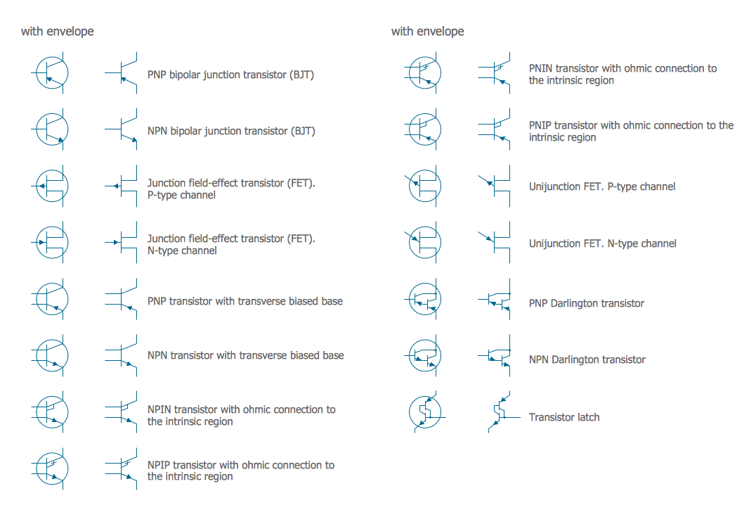
Sample 1. Audio, Video, Media Solution
In order to illustrate where the cameras are within some particular place, such as office building, etc., you can always create a CCTV system diagram for mentioning the objects in a very convenient visual way instead of making lists with lots of description of where exactly such systems are. For making the process of making such diagram fun and simple, you can always use Audio, Video, Media solution downloaded from ConceptDraw STORE application.
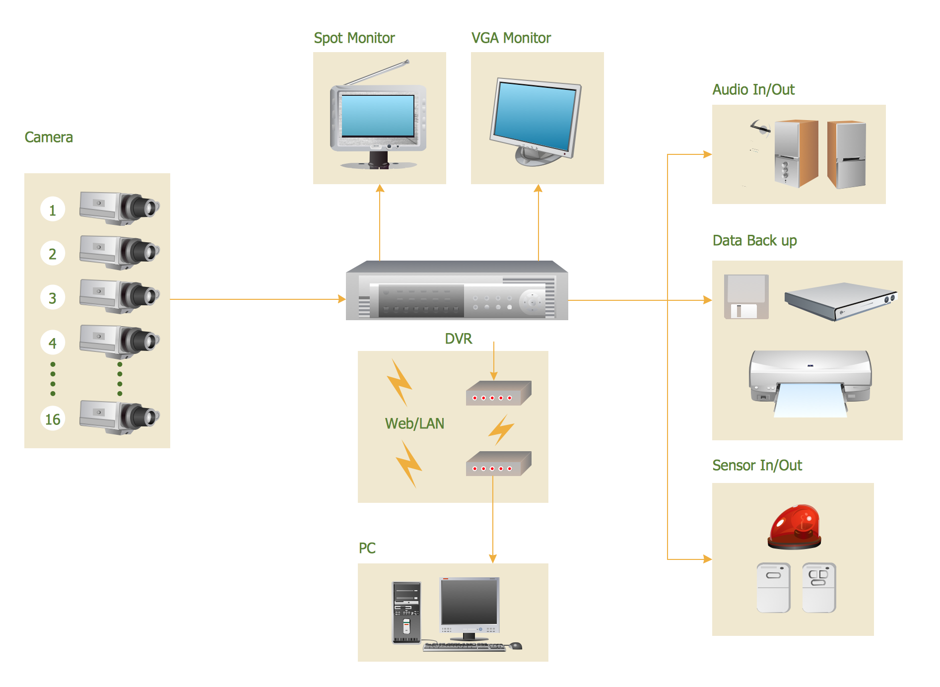
Sample 2. CCTV Surveillance System Diagram.
This CCTV system diagram was created in ConceptDraw DIAGRAM diagramming software using the Audio, Video, Media solution.
Illustrate your CCTV system using library with icons of video and TV devices from the Audio, Video, Media solution.
See also Samples:
- Illustration - Audio, video, media
- Illustration - Aerospace and Transport
- Illustration - Artwork
- Illustration - Business and finance
- Illustration - Computers and communications
- Illustration - Manufacturing
- Illustration - Nature
- Illustration - People
- Illustration - Presentation clipart
- Illustration - Safety and security
- Science & Education — illustrations