Create Floor Plans Easily with ConceptDraw DIAGRAM Floor Design Software
What is a Floor Plan?
A measurable floor plan — a drawing, which precisely depicts all the dimensions of the room. To do one, you need to measure the room and then redraw it in scale. 1:50 scale is usually used. You should start measuring the room from the door, moving in the one direction.
Such floor plan must take into account many parameters. The most important is the general dimensions of the room, its width and length, and the height of the ceiling. You also need to specify the thickness of the walls. If the premise has a window, you need to specify its height and width, and the height of the windowsill. Further, you should indicate the height and width of the doorway. In order to be able to position the furniture in the plan accurately, you can specify the binding point of utilities, such as sockets, switches, ventilation shafts, etc.

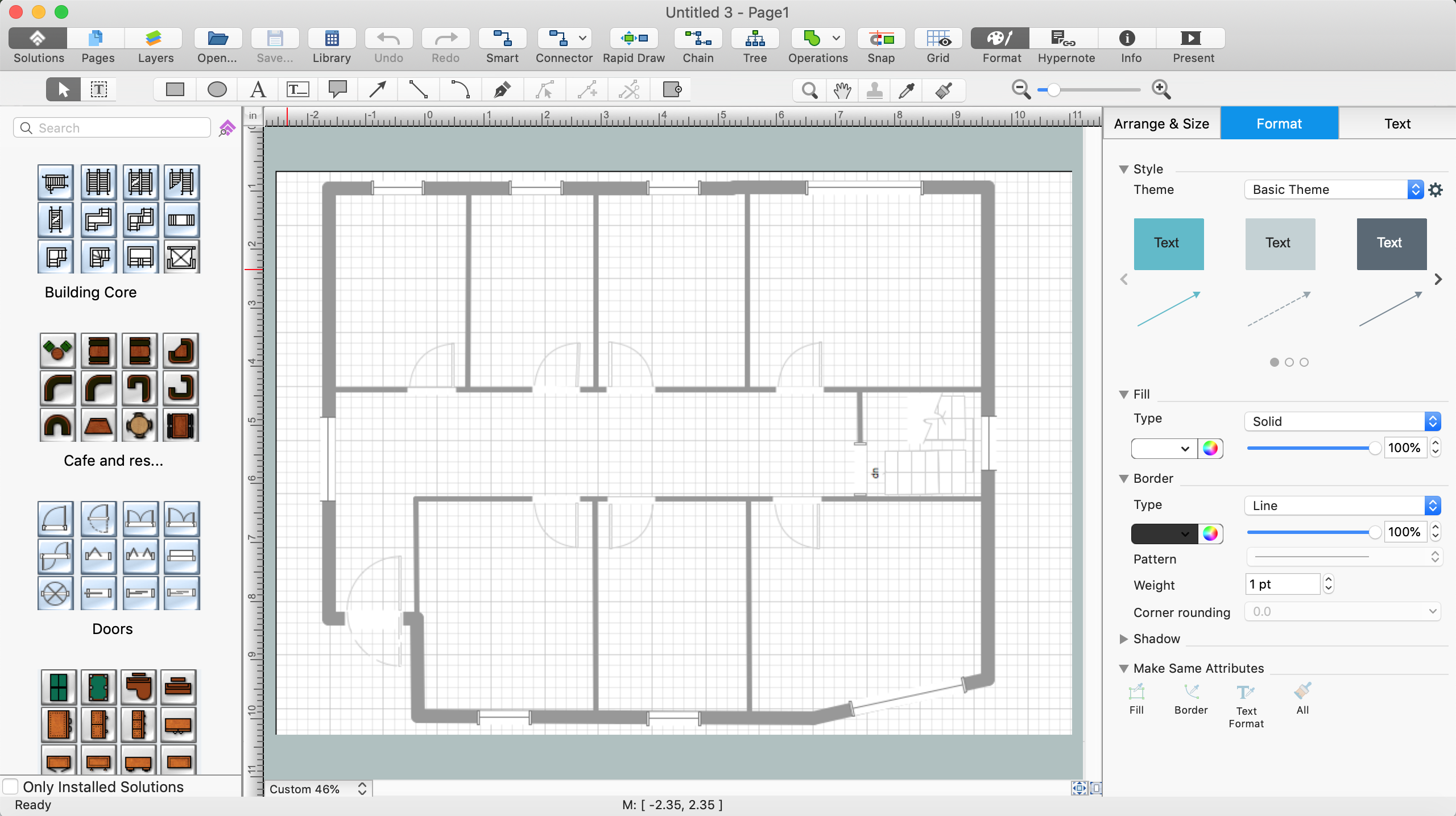
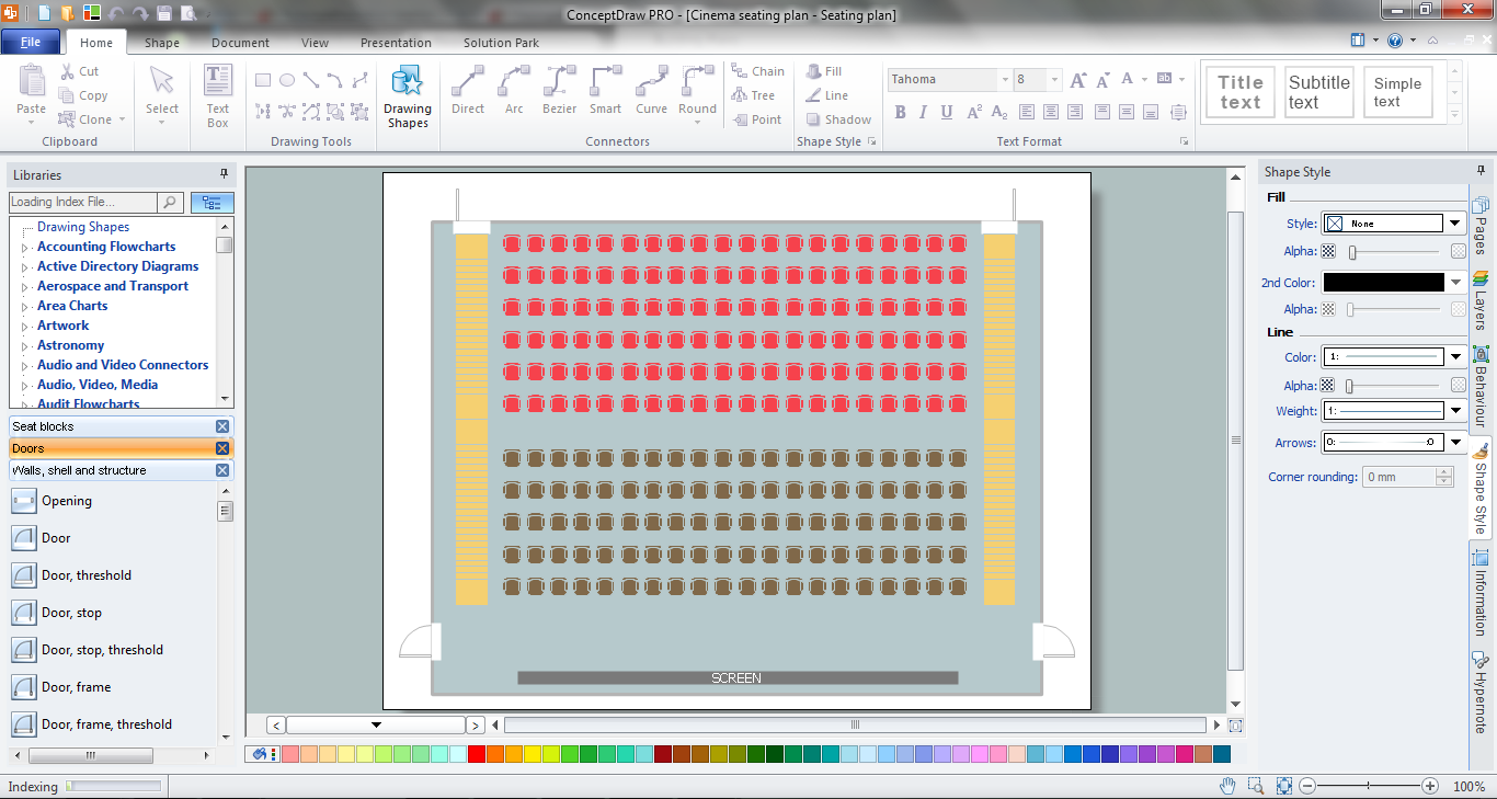
Example 1. Floor Plan
Common Mistakes to Avoid
First, you should draw a proper measurable floor plan, calculate the area of the room and divide the space into functional zones, as well as determine the dimensions of the furniture.
There are two basic ways of creating a floor plan: hiring an interior designer or designing on one’s own. Professional help can be quite expensive, and the result may not always be worth the money. Let’s take a look at what skills are needed to create the interior design on your own using floorplan app.
Creating Flooring Design Tips
Primarily, this basic knowledge of the composition rules. It helps to compose, to place the shapes and volume of the interior, to achieve balance in the room between the free space and objects. This might help to compose correctly, to place the shapes and the volumes in the interior, to achieve balance between free space and furniture in the room.
Basic color theory. There are strictly defined rules and laws, which are used to select a fitting color combinations to create a harmonious interior.
Materials science. To gain insight into this subject at an acceptable level, one should become familiar with the properties of different materials, and understand their use cases. The aesthetic aspects will be individual for each project.
Flooring design software for interior design development. To create a full-fledged interior design with your own hands you will need to learn how to make premises schemes. You can draw by hand, but it can be much easier to do with the floorplan software or floor layout app, created specifically for this purpose. Among many similar tools, there are very complex tools and easy-to-use products, such as ConceptDraw DIAGRAM floorplan drawing software.
ConceptDraw DIAGRAM Floor Design Software Benefits
With ConceptDraw DIAGRAM floorplan drawing app you can easily create the following plans and layouts:
- Basic Floor Plan,
- Office Layout,
- Office Furniture,
- Convention Plan,
- Apartment Floor,
- Hotel Floor,
- Seating Plan,
- Catering Plan.
ConceptDraw DIAGRAM floor design software is more than just house floor plan software as its functionality and features include:
| # | Functionality |
|---|---|
| 1. | Thousands of graphic objects, shapes, and symbols for designing plans and layouts for office furniture, study rooms, plumbing and piping symbols, wiring furniture, HVAC, security systems, plants, kitchen and bathroom fixtures, lighting fixtures, expo and shopping malls, reflected ceilings, seating plans, landscape elements, and more! |
| 2. | An extensive number of floor plan samples and templates to make the process of designing floor plans and layouts much easier with flooring design software! |
| 3. | Enables users to expand, shrink, mirror, rotate, move, and modify the entire floor plan and its elements without being a mathematician or artist, only using the tools of floor design program. |
| 4. | Empowers users with the power of a CAD application. |
| 5. | Multiple layers distinguish different areas of the floor plan for easier editing. |
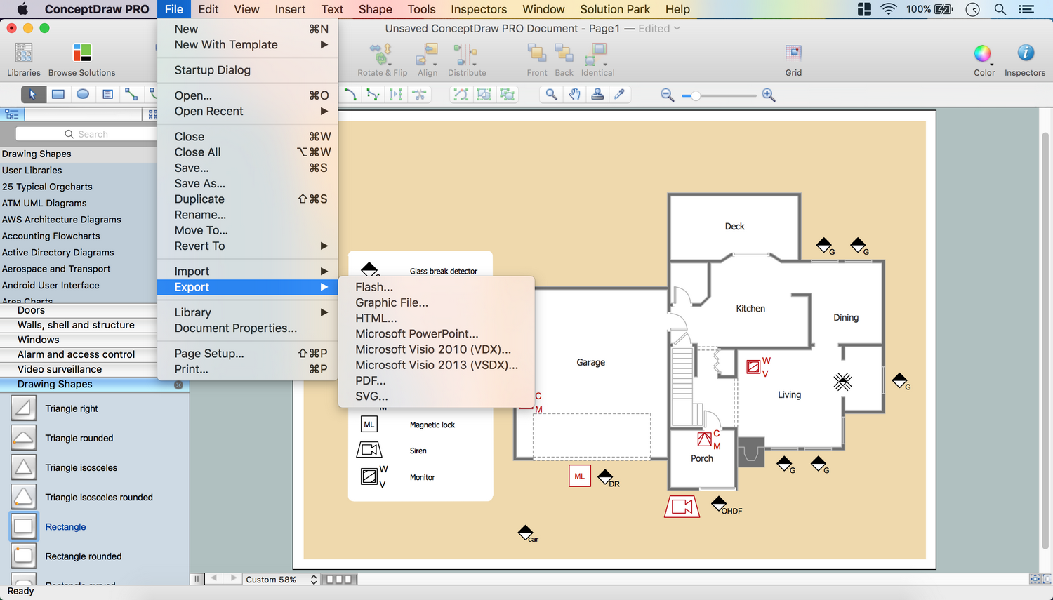
| 6. | Export to many graphic formats including PDF, Power Point, Flash or HTML with hyperlinks directly from floorplan app. |
| 7. | Hyperlink multi-page documents for easy referencing. |
| 8. | Store detailed information of floor plan elements with custom properties. |
| 9. | Annotate your home or office floor plan with rich text capabilities. |
| 10. | Customizable grid and guide lines and thousands of pre-drawn shapes for drawing floor plans. |
How To Create Floor Plan
- Launch ConceptDraw DIAGRAM floorplan software.
- Set a page orientation: File menu – Page Setup – Horizontal Orientation – Ok.

- Open Layers Tab from Inspectors. Double click on the layer – Change name.

- From the Floor Plans Solution for ConceptDraw DIAGRAM floorplan app open the libraries containing the necessary shapes:
- Doors
- Sunrooms
- Walls, Shell and Structure
- Windows

- Open Walls, shell and structure Library. Take out Room Object, place it on the page.
- Use control dots to make needed size.

- Add needed Quantity of rooms.

- Select all rooms - Align Center using Align option from the Toolbar.

- Take out Wall 1 object, place it on the page.
- Change Wall Thickness: Right click on the object – Custom Properties.
- Select Wall Thickness. Change Type to String. Change Value.

- Use control dots to adjust size. Add needed Quantity of walls.

- Select all Wall objects – Distribute them Middle via Distribute Option from the Toolbar.

- Select all (Cmd+A) – Open Inspectors – Line tab – Change color.

- Open Sunrooms library – Take out Victorian conservatory 2 object. Place it on the page.
Rotate it left via Rotate & Flip Option from the Toolbar.

- Use control dots to adjust size. Send it to back using the option from the Toolbar in floorplan software.

- File Menu – Document Properties – Page Size – Adjust to Drawing Contents – Ok.

- Inspectors – Layers tab - Select another layer for the next part of the drawing.
- Lock previous layer.

- Open Doors library. Take out needed objects; place them on the Floor plan.
- Use control dots to make needed size.

- Using Action Menu of the object you may easily Flip it, show Swing or Dimensions.

- File Menu – Document Properties – Page Size – Adjust to Drawing Contents – OK.

- Open Windows library. Take needed objects, place them on the Floor plan.
- Use control dots to make needed size.

- Select all Doors and Windows using Cmd+A.
- Open Inspectors – Line tab – Change color.

- Inspectors – Layers tab - Select another layer for the next part of the drawing.
- Lock previous layer.

- Double tap on the empty part of the page – Enter your text.
- Open Inspectors – Text tab – Edit text.

- Holding down Option button (ALT) copy the object. Place them on the page in ConceptDraw DIAGRAM floorplan software.

Now your Drawing is ready.
- You may save it or export to different formats via File Menu of ConceptDraw DIAGRAM floor layout app.


Floor Plan Examples
The Floor Plans solution for ConceptDraw DIAGRAM floor plan drawing software provides a unique collection of professionally designed Floor plan examples. This is an illustration of solution power, an inexhaustible source of inspiration and a good basis to be used and modified per your own requirements.


Use the libraries with a set of vector objects, templates and samples from the Floor Plans Solution from the Building Plans area of ConceptDraw Solution Park for designing your professional architectural designs.