Chemical Engineering
One of the branches in engineering is a chemical engineering, being the one applying the physical sciences as well as “life sciences”, such as biochemistry. Within this engineering study economics is included in terms of producing, transforming, transporting as well as use all chemicals and materials (and energy, if needed). Every chemical engineer is known to be working on designing the large-scale processes for converting raw materials, chemicals, living cells, energy and microorganisms into some useful products.
Chemical engineering emerged upon the so called “unit operations” development of chemical transformations and physical changes (crystallizations, separations, evaporations, polymerizations, filtrations, isomerization, etc.). Such unit operations are known to be a fundamental concept chemical engineering, being introduced into the course in 1905 by William Hultz Walker. Later, unit operations became one of the most important aspects of chemical engineering at many US universities as well as in London (Imperial College).
The AIChE (American Institute of Chemical Engineers) played a huge role in making chemical engineering to be considered as an independent science. It also made unit operations to be treated central in chemical engineering. Thus, it defined chemical engineering to be a science based on the so called “unit operations”. In this way, promoting the science of chemical engineering as a distinct science in Britain lead to establishing another institution in 1922 — the Institution of Chemical Engineers (IChemE), which helped to make the unit operations being considered essential within the discipline of the chemical engineering.
Later, it became clear that “unit operations” themselves were insufficient in developing the vessels developed for containing different chemical reactions — the chemical reactors. After, the so called “transport phenomena” became very popular, used for concerning the exchange of energy, mass, momentum, charge, and angular momentum between studied and observed systems, giving an analytical approach to chemical engineering science.
There have been many concerns about the safety as well as the environmental impact of chemical manufacturing facilities since 1962. The well-known “Flixborough disaster” took place in the United Kingdom in 1974 resulted in 28 deaths, also causing damage both to a chemical plant itself and the villages nearby. It happened on the 1st of June 1974, when an explosion at a chemical plant took place close to one of the villages in England – Flixborough in North Lincolnshire. After many other disasters, the IChemE required safety to be the main part of every course accredited since 1982.
Within a computer science you can always use all needed applications nowadays in order to design from a scratch as well as manage the plants, such as chemical ones. To simplify the calculations and the needed drawings there is no need left to do it all manually as there are many applications, such as ConceptDraw Pro exist, providing the useful tools for creating all needed schematics.
Working within chemical engineering science means sometimes being involved in the processes of managing the plants themselves as well as the conditions for ensuring the optimal plant operations. Most of the chemical reaction engineers are in charge for constructing the special models which can always be used within the design and reactor analysis. They use physical parameters and laboratory data for solving their problems and predicting the reactor performance. They may be responsible for creating the plans, conducting economic analyses and specification for new plants or for modifying the existing plants.
Such design engineers often design plants for meeting their clients' needs, being limited by a number of factors, such as safety standards, government regulations and, of course, the funding of such projects and so they depend of the investors for making the right decisions, who dictate the plants’ choice of process, equipment and materials. Plant construction is usually co-ordinated by “project managers” who all also depend on the investment.
All previously mentioned unit operations are used for purifying and separating the products of reactants as well as their preparing, controlling the energy transfer in the reactors within some particular project and recycling all unspent reactants. Any unit process is known to be simply the chemical equivalent of a “unit operation”, constituting the process operations. Some unit processes involve the conversion of material many means, such as thermochemical and biochemical.
ConceptDraw DIAGRAM is a powerful diagramming and vector drawing software. Extended with Chemical and Process Engineering Solution from the Industrial Engineering Area of ConceptDraw Solution Park, it became the best Chemical Engineering software.

Example 1. Chemical Engineering in ConceptDraw DIAGRAM
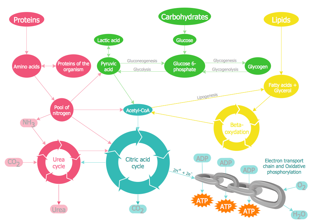
Chemical and Process Engineering Solution greatly facilitates the design process of various chemical engineering diagrams, schemes, and illustrations.


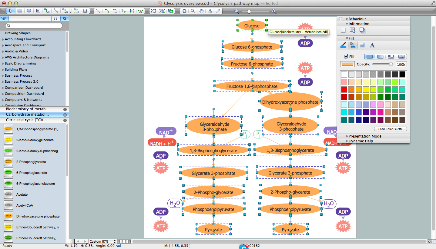
In order to design a process, you need to define the equipment sizes and types, finding out the way they are connected to each other. You also have to figure out all the available materials of construction. For such purposes, you might need a “process flow diagram” to be created, which can be done within ConceptDraw DIAGRAM software for only a few hours. Although, having ConceptDraw STORE application will lead to enabling you to do it even sooner, within only an hour or so as the mentioned application was developed especially for the ConceptDraw DIAGRAM users in order to simplify their processes of drawing only great looking schemes, such as plans and diagrams, charts, graphs, flowcharts and maps.
Thus, Chemical and Process Engineering Solution is the one providing many different stencil libraries, such as Chemical Engineering one, Heating Equipment one, Industrial Equipment one, Instruments one, Process Annotations one, Pumps Library, Valves and Fittings and the Vessels Library, which all can be used by any ConceptDraw DIAGRAM users any time they need all the professionally designed stencils from this solution.

Example 2. Chemical and Process Engineering Solution in ConceptDraw STORE
Chemical and Process Engineering Solution includes also the set of samples and templates offered in ConceptDraw STORE.

Example 3. Chemical Engineering - Amine Treating Unit Schematic Diagram
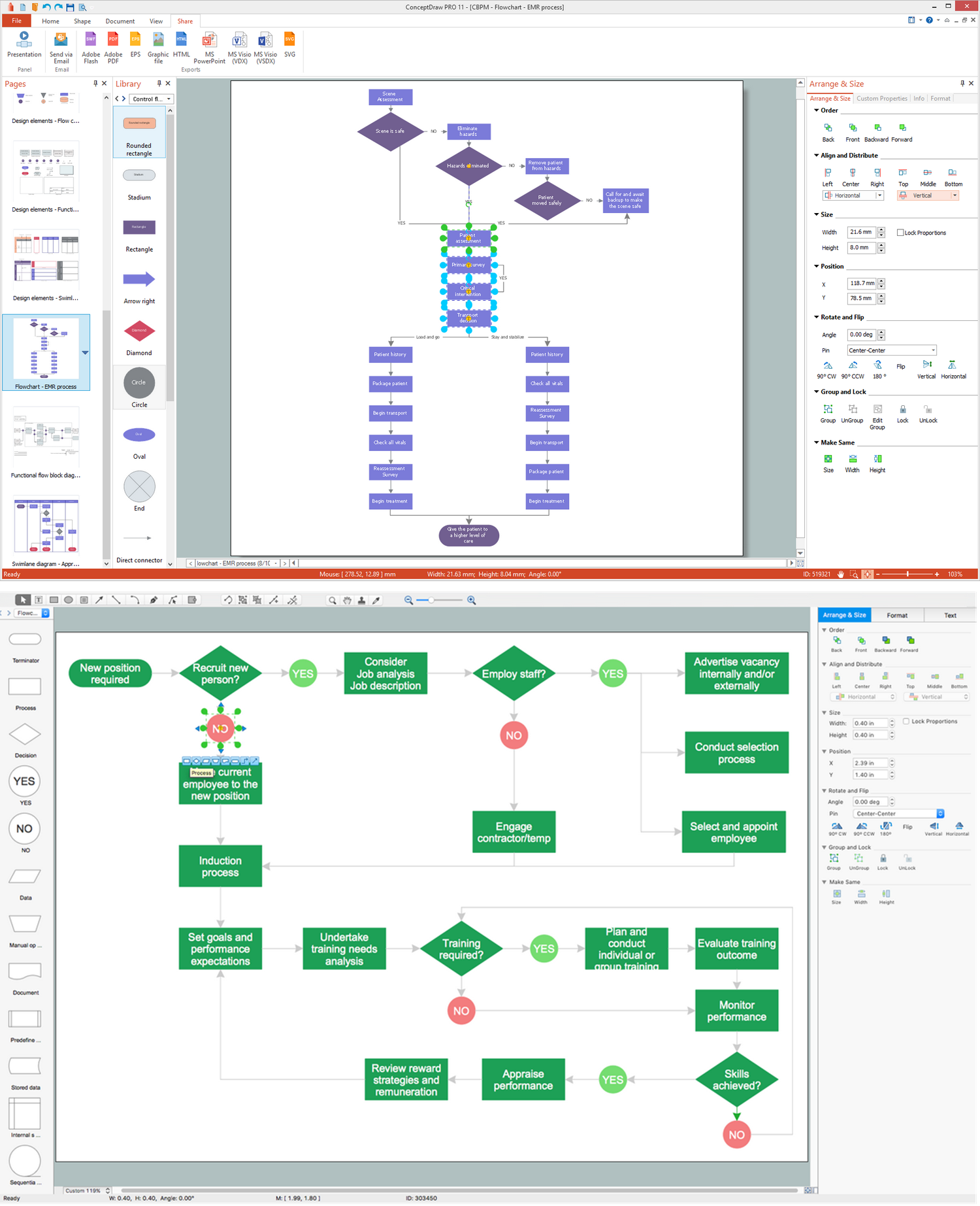
The following features make ConceptDraw DIAGRAM the best Chemical Engineering software:
- You don't need to be an artist to draw professional looking diagrams in a few minutes.
- Large quantity of ready-to-use vector objects makes your drawing diagrams quick and easy.
- Great number of predesigned templates and samples give you the good start for your own diagrams.
- ConceptDraw DIAGRAM provides you the possibility to use the grid, rules and guides. You can easily rotate, group, align, arrange the objects, use different fonts and colors to make your diagram exceptionally looking.
- All ConceptDraw DIAGRAM documents are vector graphic files and are available for reviewing, modifying, and converting to a variety of formats: image, HTML, PDF file, MS PowerPoint Presentation, Adobe Flash, MS Visio.
- Using ConceptDraw STORE you can navigate through ConceptDraw Solution Park, managing downloads and updates. You can access libraries, templates and samples directly from the ConceptDraw STORE.
- If you have any questions, our free of charge support is always ready to come to your aid.