Building Drawing Software for Design Site Plan
Using our software called ConceptDraw DIAGRAM , you’ll find lots of stencil libraries as well as many examples, templates as the drafts for your own smart diagrams, charts, flowcharts, schemes, plans and you’ll have lots of time left for yourself once you have our product.
Design Elements
ConceptDraw has examples and templates for designing Site Plan. Use they to develop the residential and commercial landscape design, parks planning, yard layouts, plat maps, outdoor recreational facilities, and irrigation systems.
ConceptDraw has 1493 vector stencils in the 49 libraries that helps you to start using software for designing Site Plan. You can use the appropriate stencils from Site Accessories library with 18 objects and Parking, Roads library with 18 objects, Trees and Plants library with 29 objects.
- Parking and Roads Library — Contains parking lots and strips, parking spaces, driveways, street junctions, and interchanges for parking facilities, on-street parking, and traffic management.
- Site Accessories Library — Contains vehicle access control equipment (tollbooth, tollgate, parking fees payment box), a handicapped sign, outdoor lighting, and garbage receptacles for parking lots and site management.
- Trees and Plants Library — Landscape design is an independent profession and a design and art tradition, practised by landscape designers, combining nature and culture. In contemporary practice landscape design bridges between landscape architecture and garden design. Landscape design focuses on both the integrated master landscape planning of a property and the specific garden design of landscape elements and plants within it.
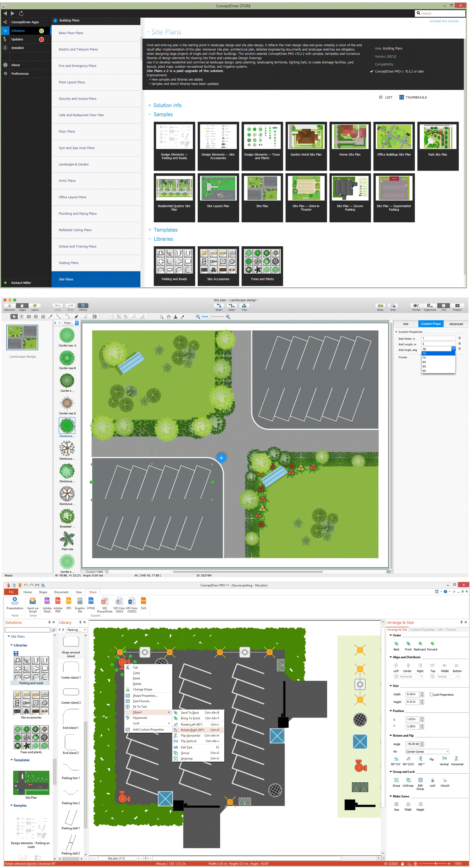
Example 1. Building Drawing Software
Site Plan solution from ConceptDraw Solution Park provides vector stencils libraries with design elements for drawing Site Plans.
Use ConceptDraw DIAGRAM diagramming and vector drawing software enhanced with Building Plans solution to draw your own residential and commercial landscape design, parks planning, yard layouts, plat maps, outdoor recreational facilities, and irrigation systems.
TEN RELATED HOW TO's:
This sample represents the actors, use cases and dependencies between them, and also the relationships between use cases. There are used dependency and use case generalization associations on this UML diagram. Use case generalization is used when you have two similar use cases, but one of them does more than another.
This sample shows the work of the Financial Trade sphere and can be used by trading companies, commercial organizations, traders, different exchanges.
Picture: Financial Trade UML Use Case Diagram Example
ConceptDraw DIAGRAM extended with Plant Layout Plans Solution from the Building Plans Area is a modern full-featured Plant Design software.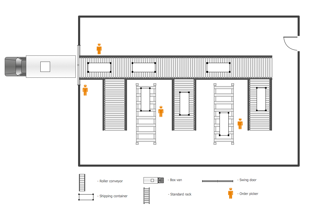
Picture: Plant Design
Related Solution:
This sample was created in ConceptDraw DIAGRAM diagramming and vector drawing software using the Floor Plans Solution from the Building Plans area of ConceptDraw Solution Park. It shows the theater architectural design. It’s very useful and necessary plan for building the new theater, for reconstruction and repair the existent theater.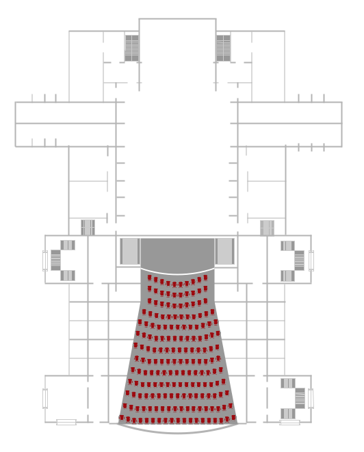
Picture: Making Architectural Designs
Related Solution:
You need quickly design Playground Layouts? Use the tools of Sport Field Plans solution from the Building Plans area of ConceptDraw Solution Park to depict any of your ideas for the Playground Layouts.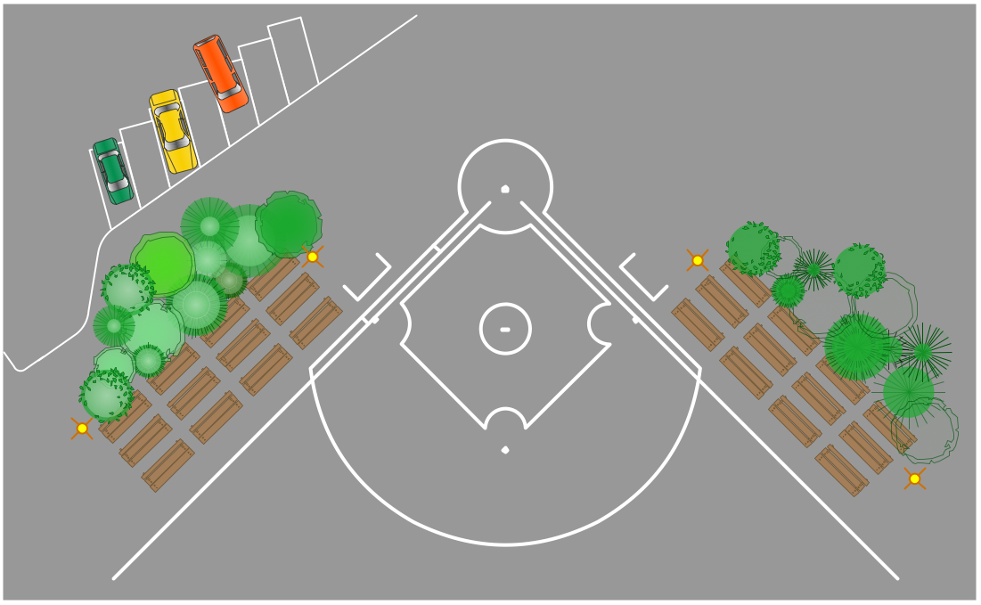
Picture: Playground Layouts
Related Solution:
It is convenient to represent various routes, directions, roads on the directional maps and navigation schemes. ConceptDraw DIAGRAM diagramming and vector drawing software supplied with Directional Maps Solution from the Maps Area of ConceptDraw Solution Park is effective for drawing Directions Maps.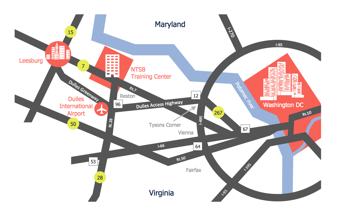
Picture: Directions Maps
Related Solution:
If you want to find a way to understand complex things in minutes, you should try to visualize data. One of the most useful tool for this is creating a flowchart, which is a diagram representing stages of some process in sequential order. There are so many possible uses of flowcharts and you can find tons of flow charts examples and predesigned templates on the Internet. Warehouse flowchart is often used for describing workflow and business process mapping. Using your imagination, you can simplify your job or daily routine with flowcharts.
Warehouse flowcharts are used to document product and information flow between sources of supply and consumers. The flowchart provides the staged guidance on how to manage each aspect of warehousing and describes such aspects as receiving of supplies; control of quality; shipment and storage and corresponding document flow. Warehouse flowchart, being actual is a good source of information. It indicates the stepwise way to complete the warehouse and inventory management process flow. Also it can be very useful for an inventory and audit procedures.
Picture: Flow Chart Example: Warehouse Flowchart
Related Solution:
The first thing that your clients will see, is your restaurant's interior. It doesn’t matter, whether you own a Michelin-starred restaurant or a lunch counter, you will need a restaurant floor plan that will reflect every detail of the establishment’s interior. It is the second most important thing after the menu. Restaurant essentials include kitchen area, dining area, restrooms, bar area, staff quarters.
Designing a layout of cafe and restaurant floor plan is a real art. It should be beautiful restaurant seating plan which convenient for visitors. Restaurant essentials include kitchen area, dining area, restrooms, bar area, staff quarters. Being planned wisely a layout of restaurant floor plan and restaurant seating chart (cafe floor plan or bar) guides to prosperous sales and good profit. Making a restaurant floor plan or restaurant seating chart involves many different elements that can be managed using ConceptDraw Cafe and Restaurant Floor Plan solution. Cafe and Restaurant library delivers a number of vector graphic objects for depicting various layouts of any style and design establishments. ConceptDraw DIAGRAM is great and simple restaurant floor plan software with thousands features.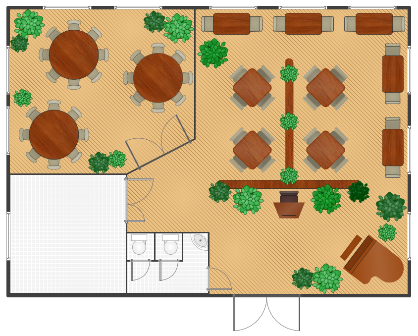
Picture: Restaurant Floor Plan
Related Solution:
The Entity-Relationship Diagram (ERD) solution from ConceptDraw Solution Park extends ConceptDraw DIAGRAM vector graphics and diagramming software with the ability to describe a database using the Entity-Relationship (Chen) model. Use it for design your ERDs and verify that ConceptDraw DIAGRAM offers the best ERD diagrams software tools for design element Chen notation._Win_Mac.png)
Picture: Entity Relationship Diagram - ERD - Software for Design Chen ER Diagrams
Related Solution:
Designing landscapes nowadays doesn’t require any special skills. Therefore, it’s not rocket science how to use landscape design software and create detailed plans and projects. Special Landscape & Garden Solution from the Building Plans area of ConceptDraw Solution Park provides vivid ready-to-use vector objects of trees, bushes, fences, furniture etc.
Picture: How To use Landscape Design Software
Related Solution:
It is important to have an electrical circuits scheme, when you plan a renovation or move to a new apartment. You have to arrange interior according to that plan, and it’s trouble-free to create wiring diagrams with ConceptDraw DIAGRAM , furthermore, this software has all the features needed to create an interior plan as well. So, get inspired by tons of examples included to ConceptDraw DIAGRAM solutions, and start your diagramming experience!
A wiring diagrams, that are represented on this drawing was created to depict the components of the electrical circuit schemes. These diagrams are created to depict the information about circuit arrangements and connections. Wiring diagrams, in contrast to physical drawings, use standard symbol's notation to depict different circuit devices and connections. That is why, wiring diagrams are applied to discover and repair electrical and electronic circuits. The vector graphic objects provided by ConceptDraw Electrical Engineering solution can help any specialist in electric engineering to design electrical schemes, circuit and wiring plans, power systems charts, and Maintenance and Repair diagrams.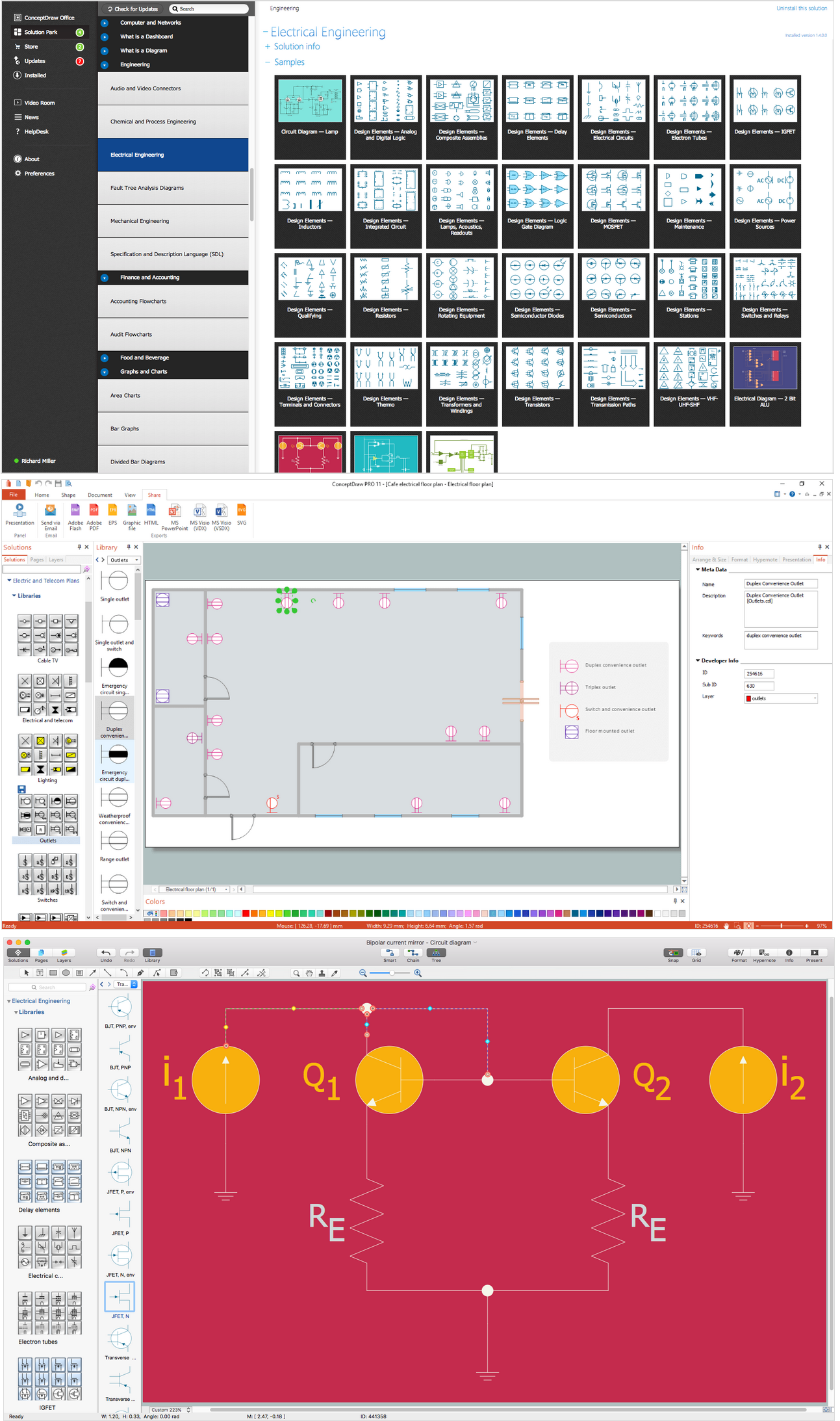
Picture: Wiring Diagrams with ConceptDraw DIAGRAM
Related Solution: